1
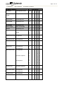
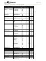
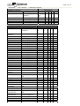
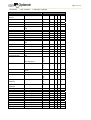
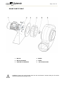
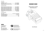
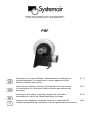
Systemair GmbH, Seehöfer Str.45, D-97944 Windischbuch, Phone:+49 (0)7930/9272-0, Fax:+49 (0)7930/9272-92, PRF Anleitungen zu Versand, Montage, Inbetriebnahme und Wartung von Industrieventilatoren für Umgebungen, in denen aggressive Gase/ Dämpfe vorhanden sein können 2 Instructions for shipping, mounting, initial operation and maintenance of industrial fans for environments where corrosive gas/vapours may be present 16 Instruktioner för leverans, montering, uppstart och underhåll av industrifläktar för miljöer där frätande gas/ångor kan finnas. 30 Instruções de embalagem, instalação, arranque e manutenção de ventiladores industriais para ambientes contendo gases/vapores corrosivos. 44 INDEX GENERAL INFORMATION .................................................................................................................... 3 HAZARD WARNINGS..............................................................................................................................3 LIMITATIONS OF USE ............................................................................................................................3 DESCRIPTION OF ACCESORIES ..........................................................................................................8 DESCRIPTION OF SAFETY DEVICES ...................................................................................................8 ENVIRONMENTAL LIMITS......................................................................................................................8 TRANSPORTATION ................................................................................................................... 8 POSSIBLE HAZARDS .............................................................................................................................8 RECOMMENDED PRECAUTIONS .........................................................................................................8 INSTALLATION .......................................................................................................................... 9 INSTALLING THE FAN ............................................................................................................................9 REQUIRED LEVEL OF EXPERTISE .................................................................................................9 RECOMMENDED PRECAUTIONS ....................................................................................................9 PROCEDURE.....................................................................................................................................9 WIRING TO THE MAINS....................................................................................................................9 MAINTENANCE ........................................................................................................................ 10 REQUIRED LEVEL OF EXPERTISE ................................................................................................................10 PREVENTIVE MEASURES ...................................................................................................................10 PROCEDURE ........................................................................................................................................10 REPAIRS................................................................................................................................... 11 REQUIRED LEVEL OF EXPERTISE .....................................................................................................11 PREVENTIVE MEASURES ...................................................................................................................11 PROCEDURE ........................................................................................................................................11 SPARE PARTS TABLE..........................................................................................................................13 CLEANING ................................................................................................................................ 14 REQUIRED LEVEL OF EXPERTISE .....................................................................................................14 HAZARD WARNINGS............................................................................................................................14 PREVENTIVE MEASURES ...................................................................................................................14 RECOMMENDED PRODUCTS .............................................................................................................14 PROCEDURE ........................................................................................................................................14 DISMANTLING.......................................................................................................................... 14 HAZARD WARNINGS............................................................................................................................14 PARTS, ELEMENTS, AND SUBSTANCES THAT REQUIRE SPECIAL PROCEDURES.....................14 ASSEMBLY AND DISMANTLING ............................................................................................ 15 REQUIRED LEVEL OF EXPERTISE .....................................................................................................15 RECOMMENDED PRECAUTIONS .......................................................................................................15 PROCEDURE ........................................................................................................................................15 REMOVAL FROM COMMISSION............................................................................................. 15 REQUIRED LEVEL OF EXPERTISE .....................................................................................................15 RECOMMENDED PRECAUTIONS .......................................................................................................15 PROCEDURE ........................................................................................................................................15 Page 2 of 14 GENERAL INFORMATION HAZARD WARNINGS − Never put your hands, or any other part of your body, into the fan casing. − Never remove, take off, modify or in any other way interfere with the protective devices. LIMITATIONS OF USE The fan has been designed and built to transport air in the presence of corrosive gas/vapours at temperatures between -15C° and +70C°. The concentration limits for transporting corrosive substances are given below. WARNING THE PRODUCTS IN THIS MANUAL ARE NOT SUITABLE FOR USE IN POTENTIALLY EXPLOSIVE (ATEX) ENVIRONMENTS. FOR USE IN POTENTIALLY EXPLOSIVE (ATEX) ENVIRONMENTS, ATEX CERTIFIED FANS OF A SUITABLE CATEGORY FOR THE ZONE CLASSIFIED SHOULD BE PURCHASED FROM SYSTEMAIR GMBH. Important: The following list has been made to the best of our knowledge and is a recommendation only. The examination of the media to be transported is under the responsibility of the system operator. We do not recommend to select material combinations with a “0” in properties. The standard casing is manufactured from PE, the standard impeller is manufactured from PP. The material of the impeller is the indicator for the selection. Page 3 of 14 + Resistant - Not resistant 0 Partially resistant CHEMICAL AGENTS BEHAVIOUR REAGENT CONCENTRATIONS TEMP PVC PP PE PVDF °C Ammonium acetate All, aqueous 20 + + + + 40 + + + + 60 0 + + + Butyl acetate Technically pure 20 - + 0 + Ethyl acetate Technically pure 20 - + + 0 0 0 - 40 Vinyl acetate Technically pure 20 - (Wine) vinegar Norm. concentrate 20 + + + + acetone Technically pure 20 - + + 0 Acetic acid Technically pure 20 0 + + + Glacial 40 - + + + 0 0 0 60 Aqueous boric acid All, aqueous + 20 + + + + 40 + + + + Hydrobromic acid 50% Aqueous 20 + + + + Citric acid 10% Aqueous 20 + + + + 40 + + + + 60 0 + + + 10% Aqueous 20 + + - + 20% Aqueous 20 + 0 - + 10% Aqueous 20 + + + + 40 + + + + 60 0 + 0 + 20 + + + + 40 + + 0 + 60 0 + 0 + 20 + + + + 40 + + 0 + 60 0 + - + 20 + 0 0 + 40 + - - + 50% Aqueous 20 + + + + 70% Aqueous 20 + + + + Fluosilicic acid 32% aqueous 20 + + + + Formic acid up to 50% aqueous 20 + + + + 40 + + 60 0 + Chloric acid Hydrochloric acid up to 30% aqueous 30% aqueous Chromic acid Hydrofluoric acid up to 50% aqueous + 0 + Page 4 of 14 + Resistant - Not resistant 0 Partially resistant CHEMICAL AGENTS REAGENT Aqueous acid BEHAVIOUR CONCENTRATIONS TEMP °C PVC PP PE PVDF phosphoric 50% Aqueous 20 + + + + 85% Aqueous 20 + + + + 40 + + + + 60 + 0 + + 20 + + + + 40 0 + + + Phthalic acid Saturated, aqueous Glycolic acid 37% aqueous 20 + + + + Lactic acid 10% aqueous 20 + + + + 40 0 + + + saturated 20 + + + + 20 40 60 20 40 20 20 + + 0 0 0 + 0 0 0 + - + + + + + + 20 40 60 20 40 20 20 40 60 20 40 60 20 40 60 20 40 20 40 60 20 20 20 20 20 20 20 40 60 20 20 20 + + 0 0 + + + + 0 + + + + + + + + + 0 0 + + + 0 + + + + + + + + + 0 0 - - + + + + + + + + + + + + + + + + 0 + + + + + 0 + Maleic acid Aqueous, cold Nitric acid Up to 40% Aqueous 65% aqueous Oxalic acid Perchloric acid 100% Aqueous, saturated cold 10% aqueous 70% aqueous Hydrogen sulphide Sulphuric acid Technically pure Up to 40% Aqueous Up to 60% Aqueous Up to 80% Aqueous 90% aqueous 96% aqueous Sulphurous acid Stearic acid Tartaric acid Trichloroacetic acid Turpentine Benzyl alcohol Ethanol Methyl alcohol Acetaldehyde Chrome alum Saturated, aqueous Technically pure All, aqueous Normal concentr. Technically pure 96% Technically pure All Technically pure Aqueous Saturated, cold + + + + + + + + + + + + + + 0 + + + + + 0 + + 0 + + + + + + + + + + + + + + + + + + + + + + + + + + + 0 + + + + + + Page 5 of 14 + Resistant - Not resistant 0 Partially resistant CHEMICAL AGENTS BEHAVIOUR REAGENT Ammonia CONCENTRATIONS Technically pure Gaseous Acetic anhydride Sulphur dioxide Aniline Liquid anti-freeze Technically pure Technically pure Technically pure CHEMICAL AGENTS REAGENT CONCENTRATIONS Petrol Traces of lead and aromatics Potassium bromate Borax Liquid bromine Butadiene Gaseous butane Cyclohexane Chlorine Chlorobenzene Chloroform Ethylene chloride Chloromethane Vinyl chloride dichlorotulene Dimethylamine 1,4-dioxane Dioctyl phthalate Ethane Ether Ethyl benzene Ethylediamine Phenol Dry fluorine Ammonium fluoride Formaldehyde Sodium phosphate Phosgene Diesel fuel Glycerine Hydrogen Ammonium hydroxide Iodine Sodium iodide Calcium hypochlorite Sodium hypochlorite Isoctane Mercury Methane TEMP °C 20 40 60 20 20 20 20 PVC + + + + PP + + + + 0 + PE + + + + 0 + PVDF + + 0 0 + Saturated, aqueous BEHAVIOUR TEMP°C PVC 20 + 40 + 60 + 20 + All, aqueous Technically pure Technically pure Technically pure Technically pure Technically pure Technically pure Humid 97% gaseous Technically pure Technically pure Technically pure Technically pure Technically pure Technically pure Technically pure Technically pure Technically pure Technically pure Technically pure Up to 10% aqueous Technically pure 50% aqueous 20 20 20 20 20 20 20 20 20 20 20 20 20 20 20 20 20 20 20 20 20 20 + + + 0 0 + 0 + 0 + + + + + 0 0 0 + + + + + 0 0 - + + 0 + 0 + + + 0 + 0 + + + 0 + + + 40% aqueous Aqueous, saturated, cold Technically pure 20 20 + + + + + + + + 20 20 20 20 20 + + + + + + + + 0 0 + + + + + + 0 20 20 20 + + + + + + + + + + + 20 + 0 0 0 20 20 20 + + + + + + + + + + + + Technically pure Technically pure Aqueous, saturated, cold Aqueous Aqueous, saturated, cold 12.5% active chlorine, aqueous Technically pure Pure Technically pure PP + + 0 + PE PVDF 0 + + + + + + + + + + + + + + + + + 0 0 + + + + + + Page 6 of 14 + Resistant - Not resistant 0 Partially resistant CHEMICAL AGENTS REAGENT CONCENTRATIONS Methyl hexyl Technically pure ketone Naphta Naphtalene Technically pure Ammonium nitrate 10% aqueous Sodium nitrate Aqueous, saturated, cold Nitrotoluene Technically pure Oleum 10% SO2 Lubricant oils Olive oil Paraffin oil Silicon oil Sodium oxalate Aqueous, saturated, cold Ethylene oxide Technically pure Oxygen Technically pure Ozone Perchloroethylene Potassium permanganate Hydrogen peroxide In the air up to 2% Technically pure Aqueous, saturated, cold 20% aqueous Petroleum 90% aqueous Technically pure Propane Sodium silicate Caustic soda Technically pure liquid All, aqueous 50% aqueous BEHAVIOUR TEMP°C PVC PP PE PVDF 20 + + 0 20 40 20 20 + 0 + + 0 + + + 0 + + + + + + + + 20 20 20 20 20 20 20 + + + + + + + + + + + + 0 + + + + + + + + + + 20 20 60 20 20 20 + 0 + + + 0 0 0 + 0 + 0 0 0 + + + + + + + + + + + + + 0 + + + 0 + 0 0 + + + + + + + + + + + + + + + + + + 0 0 0 0 0 0 + 0 + 0 0 0 + + + + + + 0 + + + + + + + + 20 40 60 20 20 40 60 20 Ammonium sulphate 10% aqueous Ammonium sulphate Tetrachloroethane Lead tetraethyl Tetrahydrofuran Toluene Trichloroethane Trichloroethylene Triethanolamine Urea Vaseline Xylene Sulphur 10% aqueous 20 20 40 60 20 40 60 20 Technically pure Technically pure Technically pure Technically pure Technically pure Technically pure Technically pure Up to 30% aqueous Technically pure Technically pure Technically pure 20 20 20 20 20 20 20 20 20 20 20 + + + + + + + + + + + + + + + 0 + 0 0 0 + 0 0 0 + + 0 + + Page 7 of 14 DESCRIPTION OF ACCESSORIES The following accessories are available for the fan on request: − Antivibration joints: reduce vibration which could be transmitted to the ventilation ducts − Shock absorbers: reduce vibration which could be transmitted to the fan base. − Butterfly valves: regulate the airflow in the ducts. − Ducts: used to connect the fan to the system. − Condensation plug: discharges condensation forming inside the casing. − Bends and reductions: join stretches of ductwork together. DESCRIPTION OF SAFETY DEVICES The fan has no active safety devices because it is designed to be part of a system which regulates its power supply and function. ENVIRONMENTAL LIMITS The fan may be installed in an environment at a temperature of between 20C° and +40C° at an altitude of no more than 1000 metres above sea level. POSSIBLE HAZARDS The fan must be transported as it is, without dismantling or removing any of its parts; it is therefore heavy and may have sharp protuberances. The fan must be thoroughly cleaned prior to transportation in order to ensure that while it is being lifted no detritus will fall out of or off it. RECOMMENDED PRECAUTIONS − WARNING: always wear adequate protective clothing. − WARNING: follow all the instructions given in this chapter. − WARNING: verify that the weightlifting equipment used can bear the declared weight in the enclosed catalogue. − Do not approach the fan under any circumstances until it is resting on the ground and the weightlifting equipment is inactive. Page 8 of 14 INSTALLATION INSTALLING THE FAN REQUIRED LEVEL OF EXPERTISE Basic understanding of masonry and skills. RECOMMENDED PRECAUTIONS − WARNING: follow the steps illustrated in this section accurately. − WARNING: always wear adequate protective clothing. − WARNING: always employ a qualified electrician to install the electrical components and wiring. − WARNING: before wiring the fan ensure that the impeller is beyond the reach of people’s arms. If it is not install a protection grill and connect it to the supply and exhaust ducts. PROCEDURE 1. 2. 3. 4. 5. 6. 7. 8. 9. Transport the packaged fan to its installation location, remove packaging. Identify the anchoring screws exact position using the fan. Drill the necessary holes. Align the fan housing’s drilled holes with those on the base. Fix the structure to the base using pressure plugs or bolts depending on whether the base is in iron or cement. Install shock absorbers if available. Connect the supply and exhaust ducts. Install fixed protection barriers in order to render the fan inaccessible under normal operating conditions. If available install the condensation drain plug at the base of the casing to drain condensation. Organise a system to channel and collect condensation. Install protection grills to avoid contact with the fan. WIRING TO THE MAINS This should be carried out once the fan is in the final position; the qualified electrician doing the wiring shall follow the instructions in the technical electrical documentation enclosed in the terminal block of the electric motor. Operation with speed controllers The admissible type of speed controller can be taken from the documentation. We recommend to use the Systemair range RTRE and RTRD, in case speed control by transformer is chosen. All motors which are speed controllable by reduction of voltage are equipped with motor protection by thermal contacts. Three phase motors shown as speed controllable can be operated with frequency inverters. The frequency inverter has to be equipped with an all pole sine filter (earth/earth and earth/phase). Three phase motors shown as single speed motors can be operated with standard frequency inverters. All single speed three phase motors are equipped with a cold conductor for motor protection. Warranty The Systemair warranty covers the complete unit and only those components supplied by Systemair. Components which have been added at site and have a negative influence on the fan invalidate the warranty for the complete fan. Systemair reserves the right in case of a warranty claim to have the concentrations of chemicals being verified by an independent third party surveyor. Page 9 of 14 MAINTENANCE REQUIRED LEVEL OF EXPERTISE CODE 1 2 3 DESCRIPTION Authorised manufacturer’s personnel only. Customer’s personnel with technical training. Customer’s personnel with technical training who have been trained for the specific maintenance involved. PREVENTIVE MEASURES WARNING: place several visible “maintenance” placards around the area. WARNING: wear protective gloves which are adequate to deal with the presence of gas/vapours and any deposits. WARNING: wear adequate protective clothing. WARNING: follow the instructions contained in the present manual. WARNING: in order to see the internal part of the casing better use a portable auxiliary lamp with a protected light bulb. WARNING: before carrying out maintenance ensure that the electrical supply to the fan has been interrupted and secured against re-starting. PROCEDURE The following tables show: • Maintenance description. • Level of expertise required. • Maintenance schedule. OPERATION Replacement of electric motor bearings and gear support, if installed. SPEC. SCHEDULING OR CRITERIA 1 30,000 hours WARNING: This operation may only be carried out by personnel authorised by the manufacturer. Page 10 of 14 REPAIRS REQUIRED LEVEL OF EXPERTISE CODE 1 2 3 DESCRIPTION Authorised manufacturer’s personnel only. Customer’s personnel with technical training. Customer’s personnel with technical training who have been trained for the specific maintenance involved. PREVENTIVE MEASURES − WARNING: place several visible “REPAIRS” placards around the area before carrying out repairs. − WARNING: wear adequate protective clothing. PROCEDURE The following table shows: • • • • A description of the problem – the commonest malfunction symptoms; Possible causes of damage; Proposed solutions; Who should intervene. SYMPTOMS Reduced air volume normal rotation speed) Excessive air volume Insufficient pressure CAUSE SOLUTIONS (at Ducts clogged and/or inlets Clean ducts and cones, check inlet blocked positioning Inverted rotation Check connection sense on the electric motors terminal block Impeller clogged Clean impeller through the dedicated hatch when the fan is not connected Insufficient rotation speed Check power supply tension and connections to the terminal motor block Rotation speed Clean ducts and cones, check inlet positioning. Check rotation direction; check any particular conditions of turbulence in the inlet; check motor rotation speed, power supply tension, winding problems. Air leak in the conductor Check the system and replace faulty system or faulty/badly components. installed components, or bypass register not perfectly shut. Clean pipes and cones, check register Rotation speed too low position. Check wiring. Inverted rotation Impeller partially and/or damaged blocked Check impeller condition and installation. SPEC 2 2 2 2 2 2 2 2 2 2 Page 11 of 14 SYMPTOMS CAUSE SOLUTIONS Reduced performance after Leak in the fan casing seal Replace seal and check ducting. a period of correct function and/or leak in the inlet/outlet ducts Start up problems Excess power absorption Reduced tension Excessive noise Vibration power Check rotation direction; check any turbulence conditions in inlet; check motor running speed, power supply tension and winding problems. supply Check data on the motor plate SPEC 2 2 2 Use soundproofing and/or silencers; High number of rpms needed opt for a larger fan with equal to obtain the required performance or a fan with a minor performance peripheral speed 2 Faulty bearings 2 Check wear and tear on bearings (especially sealed bearings) Poorly balanced impeller or Check impeller balance impeller knocking against the casing 2 Poorly balanced rotating parts Check balancing again 2 Unsuitable base 2 Add weights to the base to increase stability Page 12 of 14 SPARE PARTS TABLE 1 MOTOR 4 WHEEL 2 MOTOR SUPPORT 5 OGIVE 3 DISK MOTOR SUPPORT 6 VOLUTE MOULDED − WARNING: always use original spare parts from the manufacturer. Indicate clearly the ID number of the part required and the type of fan. Page 13 of 14 CLEANING REQUIRED LEVEL OF EXPERTISE Expert worker with machinery experience and safety training. HAZARD WARNINGS The only risks which may occur come from not following the instructions contained in the manual or not wearing adequate safety clothing. PREVENTIVE MEASURES Turn off the electric power supply. Drain off condensation in the hood. RECOMMENDED PRODUCTS Use compressed air alone if the fan is used to transport air in the presence of gas/vapours which do not contain suspended particles. If the fan is used in an environment with vapours from special chemical substances consult the chemicals safety data sheets to see which cleaning products they recommend. PROCEDURE 1. Stop the fan and cut the electrical power supply off. 2. Access the casing by dismantling it as described in section assembly and dismantling. 3. Clean the parts of the casing and the impeller using compressed air or the specific products recommended for air in the presence of gas/vapours. 4. Reassemble the casing as described in section assembly and dismantling. 5. Restart the fan if necessary. DISMANTLING HAZARD WARNINGS Mainly due to the fact that some parts of the fan are heavy. PARTS, ELEMENTS, AND SUBSTANCES THAT REQUIRE SPECIAL PROCEDURES All fan parts should be correctly disposed of. Each part, component or group of components should be grouped together by type. Procedures and equipment used must conform to legislation current at the time of dismantling. Page 14 of 14 ASSEMBLY AND DISMANTLING REQUIRED LEVEL OF EXPERTISE The operations described in the present section are referred to in several other sections of the manual. The level of expertise required is specified at the beginning of each appropriate reference section. RECOMMENDED PRECAUTIONS − WARNING: follow the instructions detailed in this section. − WARNING: wear adequate protective clothing. PROCEDURE DISMANTLING 1. 2. 3. 4. 5. 6. Turn the fan off and cut off the electrical power supply. Detach the fans inlet and outlet ducts. Unscrew the bolts which anchor the casing to the base structure and place the casing on the ground. Unscrew the bolt which anchors the impeller to the electric motor shaft. Remove the impeller and place it on the ground. Unscrew the bolts which anchor the electric motor and place the motor on the ground. ASSEMBLY 1. 2. 3. 4. 5. Screw in the bolts that anchor the electric motor. Assemble the impeller on the electric motor shaft. Screw in the bolts that anchor the impeller to the electric motor shaft. Screw in the bolts that anchor the casing to the base structure. Attach the fans inlet and outlet ducts. REMOVAL FROM COMMISSION REQUIRED LEVEL OF EXPERTISE Basic understanding of masonry and skills, with a copy of this section of the manual authorised by their employer who guarantees their correct training. RECOMMENDED PRECAUTIONS − WARNING: follow the instructions detailed in this section. − WARNING: wear adequate protective clothing. PROCEDURE 1. 2. 3. 4. Turn the fan off. Detach the electrical power supply lines from the motor. Cover the metal parts with a light coat of oil to prevent oxidization. Cover the fan with a nylon dust sheet.