1
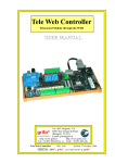
FBC-110
FBC-120
FBC-D9
FBC-2D5
FBC-114 FBC-116
FBC-L20 FBC-126
FBC-115 FBC-125
FBC-2T6 FBC-MD8
Flat BLOCK Contact - Single step
USER MANUAL
Via dell' Artigiano, 8/6
® 40016 San Giorgio di Piano
grifo
(Bologna) ITALY
E-mail: [email protected]
http://www.grifo.it
http://www.grifo.com
Tel. +39 051 892.052 (a. r.) FAX: +39 051 893.661
ITALIAN TECHNOLOGY
FBC single step
Rel. 5.00
Edition 03 September 2003
®
®
, GPC , grifo , are trade marks of grifo®
FBC-110
FBC-120
FBC-D9
FBC-2D5
FBC-114 FBC-116
FBC-L20 FBC-126
FBC-115 FBC-125
FBC-2T6 FBC-MD8
Flat BLOCK Contact - Single step
USER MANUAL
FBC 110
Flat BLOCK Contact 10 pins
Interface between a 10 pins male low profile connector and field wiring (quick release screw terminal connectors). Suitable for
DIN 46277-1 and 3 rails.
FBC 114
Flat BLOCK Contact 14 pins
Interface between a 14 pins male low profile connector and field wiring (quick release screw terminal connectors). Suitable for
DIN 46277-1 and 3 rails.
FBC 116
Flat BLOCK Contact 16 pins
Interface between a 16 pins male low profile connector and field wiring (quick release screw terminal connectors). Suitable for
DIN 46277-1 and 3 rails.
FBC 120\L20
Flat BLOCK Contact 20 pins
Interface between a 20 pins male low profile connector and field wiring (quick release screw terminal connectors). Version L20
is provided with LEDs to visualize lines status. Suitable for DIN 46277-1 and 3 rails.
FBC 126
Flat BLOCK Contact 26 pins
Interface between a 26 pins male low profile connector and field wiring (quick release screw terminal connectors). Suitable for
DIN 46277-1 and 3 rails.
FBC D9
Flat BLOCK Contact type D 9 pins
Interface between a 9 pins male or female D-type connector and field wiring (quick release screw terminal connectors). Suitable
for DIN 46277-1 and 3 rails.
FBC D15
Flat BLOCK Contact type D 15 pins
Interface between a 15 pins male or female D-type connector and field wiring (quick release screw terminal connectors). Suitable
for DIN 46277-1 and 3 rails.
FBC D25
Flat BLOCK Contact type D 25 pins
Interface between a 25 pins male or female D-type connector and field wiring (quick release screw terminal connectors). Suitable
for DIN 46277-1 and 3 rails.
FBC 2D5
Flat BLOCK Contact 2 connectors DIN type 5 pins
Interface between two 5 pins female DIN type connectors and field wiring (quick release screw terminal connectors). Suitable for
DIN 46277-1 and 3 rails.
FBC 2T6
Flat BLOCK Contact 2 connectors Plug type 6 pins
Interface between two 6 pins female telephone PLUG type connectors and field wiring (quick release screw terminal connectors).
Suitable for DIN 46277-1 and 3 rails.
FBC MD8
Flat BLOCK Contact Mini DIN type 8 pins
Interface between a 8 pins female Mini DIN connector and field wiring (quick release screw terminal connectors). Suitable for
DIN 46277-1 and 3 rails.
Via dell' Artigiano, 8/6
® 40016 San Giorgio di Piano
grifo
(Bologna) ITALY
E-mail: [email protected]
http://www.grifo.it
http://www.grifo.com
Tel. +39 051 892.052 (a. r.) FAX: +39 051 893.661
ITALIAN TECHNOLOGY
FBC single step
Rel. 5.00
Edition 03 September 2003
®
®
, GPC , grifo , are trade marks of grifo®
DOCUMENTATION COPYRIGHT BY grifo® , ALL RIGHTS RESERVED
No part of this document may be reproduced, transmitted, transcribed, stored in a
retrieval system, or translated into any language or computer language, in any form or
by any means, either electronic, mechanical, magnetic, optical, chemical, manual, or
otherwise, without the prior written consent of grifo®.
IMPORTANT
Although all the information contained herein have been carefully verified, grifo®
assumes no responsability for errors that might appear in this document, or for damage
to things or persons resulting from technical errors, omission and improper use of this
manual and of the related software and hardware.
grifo® reserves the right to change the contents and form of this document, as well as the
features and specification of its products at any time, without prior notice, to obtain
always the best product.
For specific informations on the components mounted on the card, please refer to the
Data Book of the builder or second sources.
SYMBOLS DESCRIPTION
In the manual could appear the following symbols:
Attention: Generic danger
Attention: High voltage
Trade Marks
, GPC®, grifo® : are trade marks of grifo®.
Other Product and Company names listed, are trade marks of their respective companies.
grifo®
ITALIAN TECHNOLOGY
GENERAL INDEX
INTRODUCTION ........................................................................................................................ 1
CARD VERSION ......................................................................................................................... 1
GENERAL INFORMATION ...................................................................................................... 2
TECHNICAL FEATURES OF FBC 110 .................................................................................... 4
GENERAL FEATURES .......................................................................................................... 4
PHISICAL FEATURES .......................................................................................................... 4
TECHNICAL FEATURES OF FBC 114 .................................................................................... 6
GENERAL FEATURES .......................................................................................................... 6
PHISICAL FEATURES .......................................................................................................... 6
TECHNICAL FEATURES OF FBC 116 .................................................................................... 8
GENERAL FEATURES .......................................................................................................... 8
PHISICAL FEATURES .......................................................................................................... 8
TECHNICAL FEATURES OF FBC 120 .................................................................................. 10
GENERAL FEATURES ........................................................................................................ 10
PHISICAL FEATURES ........................................................................................................ 10
TECHNICAL FEATURES OF FBC L20 ................................................................................. 12
GENERAL FEATURES ........................................................................................................ 12
PHISICAL FEATURES ........................................................................................................ 12
CN1 - INTERFACE FOR INPUTS OF CI/O-01, CI/O-02, CI/O-T16, CI/O-R16 ........... 13
CN2 - CONNECTOR FOR OPTOCOUPLED INPUTS OF SECTION B ...................... 14
CN3 - CONNECTOR FOR OPTOCOUPLED INPUTS OF SECTION A ...................... 15
CN4 - CONNECTOR FOR OPTOCOUPLERS POWER SUPPLY ................................ 16
VISUAL SIGNALATIONS ................................................................................................... 17
TECHNICAL FEATURES OF FBC 126 .................................................................................. 18
GENERAL FEATURES ........................................................................................................ 18
PHISICAL FEATURES ........................................................................................................ 18
TECHNICAL FEATURES OF FBC D9 (M/F) ........................................................................ 20
GENERAL FEATURES ........................................................................................................ 20
PHISICAL FEATURES ........................................................................................................ 20
TECHNICAL FEATURES OF FBC 115 (M/F) ....................................................................... 22
GENERAL FEATURES ........................................................................................................ 22
PHISICAL FEATURES ........................................................................................................ 22
FBC XXX
Rel. 5.00
Page I
grifo®
ITALIAN TECHNOLOGY
TECHNICAL FEATURES OF FBC 125 (M/F) ....................................................................... 24
GENERAL FEATURES........................................................................................................ 24
PHISICAL FEATURES ........................................................................................................ 24
TECHNICAL FEATURES OF FBC 2D5 ................................................................................. 26
GENERAL FEATURES........................................................................................................ 26
PHISICAL FEATURES ........................................................................................................ 26
TECHNICAL FEATURES OF FBC 2T6 ................................................................................. 28
GENERAL FEATURES........................................................................................................ 28
PHISICAL FEATURES ........................................................................................................ 28
TECHNICAL FEATURES OF FBC MD8 ............................................................................... 30
GENERAL FEATURES........................................................................................................ 30
PHISICAL FEATURES ........................................................................................................ 30
EXTERNAL CARDS ................................................................................................................. 32
APPENDIX A: ALPHABETICAL INDEX ............................................................................ A-1
Page II
FBC XXX
Rel. 5.00
grifo®
ITALIAN TECHNOLOGY
FIGURE INDEX
FIGURE 1: PHOTO OF SEVERAL FBC ................................................................................................. 3
FIGURE 2: PHOTO OF AN FBC 110 PROVIDED WITH BLOCK CONTAINER ......................................... 5
FIGURE 3: FBC 110 CONNECTION DIAGRAM ..................................................................................... 5
FIGURE 4: PHOTO OF AN FBC 114 PROVIDED WITH BLOCK CONTAINER ......................................... 7
FIGURE 5: FBC 114 CONNECTION DIAGRAM ..................................................................................... 7
FIGURE 6: PHOTO OF AN FBC 116 PROVIDED WITH BLOCK CONTAINER ......................................... 9
FIGURE 7: FBC 116 CONNECTION DIAGRAM ..................................................................................... 9
FIGURE 8: PHOTO OF AN FBC 120 PROVIDED WITH BLOCK CONTAINER ....................................... 11
FIGURE 9: FBC 120 CONNECTION DIAGRAM ................................................................................... 11
FIGURE 10: CN1 - DIRECT INTERFACE TO INPUTS ........................................................................... 13
FIGURE 11: CN2 - CONNECTOR FOR OPTOCOUPLED INPUTS OF SECTION B ....................................... 14
FIGURE 12: CN3 - CONNECTOR FOR OPTOCOUPLED INPUTS OF SECTION A ...................................... 15
FIGURE 13: CN4 - CONNECTOR FOR OPTOCOUPLERS POWER SUPPLY ............................................... 16
FIGURE 14: PHOTO OF AN FBC 126 PROVIDED WITH BLOCK CONTAINER ..................................... 19
FIGURE 15: FBC 126 CONNECTION DIAGRAM ................................................................................. 19
FIGURE 16: FBC D9F CONNECTION DIAGRAM ................................................................................ 20
FIGURE 17: PHOTO OF AN FBC D9M PROVIDED WITH BLOCK CONTAINER .................................. 21
FIGURE 18: FBC D9M CONNECTION DIAGRAM .............................................................................. 21
FIGURE 19: PHOTO OF AN FBC 115 PROVIDED WITH BLOCK CONTAINER ..................................... 23
FIGURE 20: FBC 115 CONNECTION DIAGRAM ................................................................................. 23
FIGURE 21: PHOTO OF AN FBC 125 PROVIDED WITH BLOCK CONTAINER ..................................... 25
FIGURE 22: FBC 125 CONNECTION DIAGRAM ................................................................................. 25
FIGURE 23: PHOTO OF AN FBC 2D5 PROVIDED WITH BLOCK CONTAINER .................................... 27
FIGURE 24: FBC 2D5 CONNECTION DIAGRAM ................................................................................ 27
FIGURE 25: PHOTO OF AN FBC 2T6 PROVIDED WITH BLOCK CONTAINER .................................... 29
FIGURE 26: FBC 2T6 CONNECTION DIAGRAM ................................................................................ 29
FIGURE 27: PHOTO OF AN FBC MD8 PROVIDED WITH BLOCK CONTAINER .................................. 31
FIGURE 28: FBC MD8 CONNECTION DIAGRAM .............................................................................. 31
FBC XXX
Rel. 5.00
Page III
grifo®
Page IV
ITALIAN TECHNOLOGY
FBC XXX
Rel. 5.00
ITALIAN TECHNOLOGY
grifo®
INTRODUCTION
The use of these devices has turned - IN EXCLUSIVE WAY - to specialized personnel.
The purpose of this handbook is to give the necessary information to the cognizant and sure use of
the products. They are the result of a continual and systematic elaboration of data and technical tests
saved and validated from the manufacturer, related to the inside modes of certainty and quality of
the information.
The reported data are destined- IN EXCLUSIVE WAY- to specialized users, that can interact with
the devices in safety conditions for the persons, for the machine and for the enviroment, impersonating
an elementary diagnostic of breakdowns and of malfunction conditions by performing simple
functional verify operations , in the height respect of the actual safety and health norms.
The informations for the installation, the assemblage, the dismantlement, the handling, the adjustment,
the reparation and the contingent accessories, devices etc. installation are destined - and then
executable - always and in exclusive way from specialized warned and educated personnel, or
directly from the TECHNICAL AUTHORIZED ASSISTANCE, in the height respect of the
manufacturer recommendations and the actual safety and health norms.
The devices can't be used outside a box. The user must always insert the cards in a container that
rispect the actual safety normative. The protection of this container is not threshold to the only
atmospheric agents, but specially to mechanic, electric, magnetic, etc. ones.
To be on good terms with the products, is necessary guarantee legibility and conservation of the
manual, also for future references. In case of deterioration or more easily for technical updates,
consult the AUTHORIZED TECHNICAL ASSISTANCE directly.
To prevent problems during card utilization, it is a good practice to read carefully all the informations
of this manual. After this reading, the user can use the general index and the alphabetical index,
respectly at the begining and at the end of the manual, to find information in a faster and more easy
way.
CARD VERSION
The present handbook is reported to FBC card release:
FBC 110: 020194
FBC L20: 120495
FBC 125: 120495
FBC 114: 020194
FBC 126: 020194
FBC 2D5: 020194
FBC 116: 120495
FBC D9: 120495
FBC 2T6: 020194
FBC 120: 020194
FBC 115: 120495
FBC MD8: 020194
The validity of the bring informations is subordinate to the number of the card release.
The user must always verify the correct correspondence among the two denotations.
On the card the release number is present in more points both board printed diagram (serigraph) and
printed circuit.
FBC XXX
Rel. 5.00
Page 1
grifo®
ITALIAN TECHNOLOGY
GENERAL INFORMATION
FBC (Flat BLOCK Contact) are BLOCK type modules, they allow to interface and arrange the
signals from flat-cable connectors and the field wiring in the most efficent way.
Arranges signals are available from quick release screw terminal connectors.
To easy the use of these modules, an univocal correspondance between pins of quick release screw
terminal connectors and other connectors has been decided.
FBC modules have been designed to make easier the electric panels wiring but also to be used in
laboratories.
In fact, during test phases it is often required to interface signals available on flat-cables directly with
circuits to test.
In general, FBC allow to reach all signals available from ABACO® industrial listing boards' flat
cables.
To easy the recognition of the several modules installed in the electric panel, and to locate them faster
in the electric diagram, it is possible to put an identification number directly on the BLOCK module.
In fact the serigraph features a label, preceeded by BLOCK denomination, where the user can write
any kind of identification string.
This feature of ABACO® BLOCK serie denotes the care used by grifo® in examining electric panels
installation pratical problems of one's users.
Another serigraph contains the five figures BLOCK serial number and the three circles indicating
the operational tests that the module has overcome succesfully.
Modules are provided with isolating support for omega rails type DIN 46277-1 and 46277-3
installation.
Page 2
FBC XXX
Rel. 5.00
ITALIAN TECHNOLOGY
grifo®
FIGURE 1: PHOTO OF SEVERAL FBC
FBC XXX
Rel. 5.00
Page 3
grifo®
ITALIAN TECHNOLOGY
TECHNICAL FEATURES OF FBC 110
GENERAL FEATURES
Best use:
Arrange the signals of a 10 pins low profile connector of a GPC®
or a peripheral card to a quick release screw terminal connector,
for example:
signals of RS 422, RS 485 and current loop interface of GPC®
188F, GPC® 15A, etc. or LEDs control signals of RKD LT.
PHISICAL FEATURES
Size:
72 x 65 x 25 mm
Weight:
45 g
Connectors:
CN1: quick release screw terminal, 5 pins, straight, male
CN2: low profile 10 pins, straight, male
CN3: quick release screw terminal, 5 pins, straight, male
Page 4
FBC XXX
Rel. 5.00
grifo®
ITALIAN TECHNOLOGY
FIGURE 2: PHOTO OF AN FBC 110 PROVIDED WITH BLOCK CONTAINER
1
2
2
1
3
4
4
3
5
6
6
5
7
8
8
7
9
10
10
9
FIGURE 3: FBC 110 CONNECTION DIAGRAM
FBC XXX
Rel. 5.00
Page 5
grifo®
ITALIAN TECHNOLOGY
TECHNICAL FEATURES OF FBC 114
GENERAL FEATURES
Best use:
Arrange the signals of a 14 pins low profile connector of a GPC®
or a peripheral card to a quick release screw terminal connector,
for example part of the signals of a wider connector.
PHISICAL FEATURES
Size:
72 x 65 x 25 mm
Weight:
45 g
Connectors:
CN1: quick release screw terminal, 7 pins, straight, male
CN2: low profile 14 pins, straight, male
CN3: quick release screw terminal, 7 pins, straight, male
Page 6
FBC XXX
Rel. 5.00
grifo®
ITALIAN TECHNOLOGY
FIGURE 4: PHOTO OF AN FBC 114 PROVIDED WITH BLOCK CONTAINER
1
2
3
4
2
1
4
3
5
6
6
5
7
8
8
7
9
10
10
9
11
12
12
11
13
14
14
13
FIGURE 5: FBC 114 CONNECTION DIAGRAM
FBC XXX
Rel. 5.00
Page 7
grifo®
ITALIAN TECHNOLOGY
TECHNICAL FEATURES OF FBC 116
GENERAL FEATURES
Best use:
Arrange the signals of a 16 pins low profile connector of a GPC®
or a peripheral card to a quick release screw terminal connector,
for example:
signals of RS 232 interface and Timer/Counter of GPC® 188F,
etc. or signals or RS 422 and current loop interface of RKD LT.
PHISICAL FEATURES
Size:
72 x 65 x 25 mm
Weight:
45 g
Connectors:
CN1: quick release screw terminal, 8 pins, straight, male
CN2: low profile 16 pins, straight, male
CN3: quick release screw terminal, 8 pins, straight, male
Page 8
FBC XXX
Rel. 5.00
grifo®
ITALIAN TECHNOLOGY
FIGURE 6: PHOTO OF AN FBC 116 PROVIDED WITH BLOCK CONTAINER
1
2
2
1
3
4
4
3
5
6
6
5
7
8
8
7
9
10
11
12
10
9
12
11
13
14
15
16
14
13
16
15
FIGURE 7: FBC 116 CONNECTION DIAGRAM
FBC XXX
Rel. 5.00
Page 9
grifo®
ITALIAN TECHNOLOGY
TECHNICAL FEATURES OF FBC 120
GENERAL FEATURES
Best use:
Arrange the signals of a 16 pins low profile connector of a GPC®
or a peripheral card to a quick release screw terminal connector,
for example:
signals of standard interface I/O ABACO®.
PHISICAL FEATURES
Size:
72 x 65 x 25 mm
Weight:
45 g
Connectors:
CN1: quick release screw terminal, 10 pins, straight, male
CN2: low profile 20 pins, straight, male
CN3: quick release screw terminal, 10 pins, straight, male
Page 10
FBC XXX
Rel. 5.00
grifo®
ITALIAN TECHNOLOGY
FIGURE 8: PHOTO OF AN FBC 120 PROVIDED WITH BLOCK CONTAINER
1
2
3
4
2
1
4
3
5
6
6
5
7
8
8
7
9
10
10
9
11
12
12
11
13
14
14
13
15
16
17
18
16
15
18
17
19
20
19
20
FIGURE 9: FBC 120 CONNECTION DIAGRAM
FBC XXX
Rel. 5.00
Page 11
grifo®
ITALIAN TECHNOLOGY
TECHNICAL FEATURES OF FBC L20
GENERAL FEATURES
Best use:
Arrange the signals of cards like, for example, CI/O 01,
CI/O 02, CI/O T16 and CI/O-R16 with field wiring and
visualize status of signals on the 20 pins connector..
Signals naming is compliant with grifo® standard.
PHISICAL FEATURES
Size:
72 x 65 x 25 mm
Weight:
67 g
Connectors:
CN1: low profile 20 pins, straight, male
CN2: quick release screw terminal, 9 pins, straight, male
CN3: quick release screw terminal, 9 pins, straight, male
CN4: quick release screw terminal, 2 pins, straight, male
Page 12
FBC XXX
Rel. 5.00
grifo®
ITALIAN TECHNOLOGY
CN1 - INTERFACE FOR INPUTS OF CI/O-01, CI/O-02, CI/O-T16, CI/O-R16
Allows to interface directly to 16 inputs provided by the above mentioned cards, making available
connection to the field for their signals on quick release screw terminal connectors CN2, CN3 e CN4.
Ingresso D3 Byte B
1
2
Ingresso D4 Byte B
Ingresso D2 Byte B
3
4
Ingresso D5 Byte B
Ingresso D1 Byte B
5
6
Ingresso D6 Byte B
Ingresso D0 Byte B
7
8
Ingresso D7 Byte B
Ingresso D7 Byte A
9
10
Ingresso D0 Byte A
Ingresso D6 Byte A
11
12
Ingresso D1 Byte A
Ingresso D5 Byte A
13
14
Ingresso D2 Byte A
Ingresso D4 Byte A
15
16
Ingresso D3 Byte A
+Vdc opto
17
18
+Vdc opto
Comune Vdc opto
19
20
Comune Vdc opto
FIGURE 10: CN1 - DIRECT INTERFACE TO INPUTS
Signals description:
Input Dn Byte A
Input Dn Byte B
+Vdc opto
Common Vdc opto
FBC XXX
= I - Open collector NPN input connected to n-th signal of Byte A.
= I - Open collector NPN input connected to n-th signal of Byte B.
=
- Positive terminal of inputs power supply.
=
- Common terminal of inputs power supply.
Rel. 5.00
Page 13
grifo®
ITALIAN TECHNOLOGY
CN2 - CONNECTOR FOR OPTOCOUPLED INPUTS OF SECTION B
CN2 is a 9 pins quick release screw terminal connector.
It allows to connect 8 out of 16 NPN optocoupled inputs of section B.
Connector featurs open collector optocoupled inputs and their power supply common terminal.
1
2
3
4
5
6
7
8
9
Ingresso D0 Byte B
Ingresso D1 Byte B
Ingresso D2 Byte B
Ingresso D3 Byte B
Ingresso D4 Byte B
Ingresso D5 Byte B
Ingresso D6 Byte B
Ingresso D7 Byte B
Comune Vdc opto
FIGURE 11: CN2 - CONNECTOR FOR OPTOCOUPLED INPUTS OF SECTION B
Signals description:
Ingresso Dn Byte B
Comune Vdc opto
Page 14
= I - Open collector NPN input connected to n-th signal of Byte B.
=
- Common terminal of inputs power supply.
FBC XXX
Rel. 5.00
grifo®
ITALIAN TECHNOLOGY
CN3 - CONNECTOR FOR OPTOCOUPLED INPUTS OF SECTION A
CN3 is a 9 pins quick release screw terminal connector.
It allows to connect 8 out of 16 NPN optocoupled inputs of section A.
Connector featurs open collector optocoupled inputs and their power supply common terminal.
1
2
3
4
5
6
7
8
9
Ingresso D0 Byte A
Ingresso D1 Byte A
Ingresso D2 Byte A
Ingresso D3 Byte A
Ingresso D4 Byte A
Ingresso D5 Byte A
Ingresso D6 Byte A
Ingresso D7 Byte A
Comune Vdc opto
FIGURE 12: CN3 - CONNECTOR FOR OPTOCOUPLED INPUTS OF SECTION A
Signals description:
Ingresso Dn Byte A
Comune Vdc opto
FBC XXX
= I - Open collector NPN input connected to n-th signal of Byte A.
=
- Common terminal of inputs power supply.
Rel. 5.00
Page 15
grifo®
ITALIAN TECHNOLOGY
CN4 - CONNECTOR FOR OPTOCOUPLERS POWER SUPPLY
CN4 is a 2 pins quick release screw terminal connector.
It allows to supply optocouplers circuitery with galvanically isolated power source.
1
2
Comune Vdc opto
+Vdc opto
FIGURE 13: CN4 - CONNECTOR FOR OPTOCOUPLERS POWER SUPPLY
Signals description:
+Vdc opto
Comune Vdc opto
Page 16
=
=
- Positive terminal of optocoupled inputs power supply.
- Common terminal of optocoupled inputs power supply.
FBC XXX
Rel. 5.00
ITALIAN TECHNOLOGY
grifo®
VISUAL SIGNALATIONS
FBC L20 is provided with 16 LEDs that indicated the status of input signal they are connected to;
correspondance between optocoupled inputs and LEDs is:
LD1
LD2
LD3
LD4
LD5
LD6
LD7
LD8
-
Input D0 Byte B
Input D1 Byte B
Input D2 Byte B
Input D3 Byte B
Input D4 Byte B
Input D5 Byte B
Input D6 Byte B
Input D7 Byte B
LD9
LD10
LD11
LD12
LD13
LD14
LD15
LD16
-
Input D0 Byte A
Input D1 Byte A
Input D2 Byte A
Input D3 Byte A
Input D4 Byte A
Input D5 Byte A
Input D6 Byte A
Input D7 Byte A
FBC XXX
Rel. 5.00
Page 17
grifo®
ITALIAN TECHNOLOGY
TECHNICAL FEATURES OF FBC 126
GENERAL FEATURES
Best use:
Arrange the signals of a 26 pins low profile connector of a GPC®
or a peripheral card to a quick release screw terminal connector,
for example:
signals of I/O interface of GPC® 884 or GPC® 15A.
PHISICAL FEATURES
Size:
72 x 65 x 25 mm
Weight:
45 g
Connectors:
CN1: quick release screw terminal, 13 pins, straight, male
CN2: low profile 26 pins, straight, male
CN3: quick release screw terminal, 13 pins, straight, male
Page 18
FBC XXX
Rel. 5.00
grifo®
ITALIAN TECHNOLOGY
FIGURE 14: PHOTO OF AN FBC 126 PROVIDED WITH BLOCK CONTAINER
1
2
3
4
5
6
2
1
4
3
6
5
7
8
8
7
9
10
11
12
10
9
12
11
13
14
14
13
15
16
16
15
17
18
18
17
19
20
20
19
21
22
22
21
23
24
23
24
25
25
26
26
FIGURE 15: FBC 126 CONNECTION DIAGRAM
FBC XXX
Rel. 5.00
Page 19
grifo®
ITALIAN TECHNOLOGY
TECHNICAL FEATURES OF FBC D9 (M/F)
GENERAL FEATURES
Best use:
Arrange the signals of a 9 pins D-type connector of a GPC®
or a peripheral card to a quick release screw terminal connector,
for example:
signals of a RS 232, RS 422, RS 485 or current loop serial line.
PHISICAL FEATURES
Size:
72 x 65 x 25 mm
Weight:
45 g
Connectors:
CN1: D-type connector (male or female), 9 pins, 90 degreeses
CN2: quick release screw terminal, 9 pins, straight, male
9
5
8
4
7
3
6
2
5
1
9
8
7
6
1
2
3
4
FIGURE 16: FBC D9F CONNECTION DIAGRAM
Page 20
FBC XXX
Rel. 5.00
grifo®
ITALIAN TECHNOLOGY
FIGURE 17: PHOTO OF AN FBC D9M PROVIDED WITH BLOCK CONTAINER
5
5
4
4
3
3
2
2
1
1
9
8
7
6
6
7
8
9
FIGURE 18: FBC D9M CONNECTION DIAGRAM
FBC XXX
Rel. 5.00
Page 21
grifo®
ITALIAN TECHNOLOGY
TECHNICAL FEATURES OF FBC 115 (M/F)
GENERAL FEATURES
Best use:
Arrange the signals of a 15 pins D-type connector of a GPC®
or a peripheral card to a quick release screw terminal connector,
for example:
signals of thermocouples available on IPC 52 or several signals
(serial lines, digital outputs, etc.) available on UAR 24.
PHISICAL FEATURES
Size:
72 x 65 x 25 mm
Weight:
45 g
Connectors:
CN1: quick release screw terminal, 7 pins, straight, male
CN2: D-type connector (male or female), 15 pins, straight
CN3: quick release screw terminal, 8 pins, straight, male
Page 22
FBC XXX
Rel. 5.00
grifo®
ITALIAN TECHNOLOGY
FIGURE 19: PHOTO OF AN FBC 115 PROVIDED WITH BLOCK CONTAINER
1
2
3
4
5
1
9
9
10
10
11
11
12
12
13
13
14
14
15
15
2
3
4
5
6
6
7
7
8
8
FIGURE 20: FBC 115 CONNECTION DIAGRAM
FBC XXX
Rel. 5.00
Page 23
grifo®
ITALIAN TECHNOLOGY
TECHNICAL FEATURES OF FBC 125 (M/F)
GENERAL FEATURES
Best use:
Arrange the signals of a 25 pins D-type connector of a GPC®
or a peripheral card to a quick release screw terminal connector,
for example:
signals of serial interface RS 232, RS 422, RS 485 or current
loop on several cards or signals to optical fiber interface
available on IBC 01.
PHISICAL FEATURES
Size:
72 x 65 x 25 mm
Weight:
86 g
Connectors:
CN1: quick release screw terminal, 12 pins, straight, male
CN2: D-type connector (male or female), 25 pins, straight
CN3: quick release screw terminal, 13 pins, straight, male
Page 24
FBC XXX
Rel. 5.00
grifo®
ITALIAN TECHNOLOGY
FIGURE 21: PHOTO OF AN FBC 125 PROVIDED WITH BLOCK CONTAINER
1
1
2
2
3
3
4
4
5
5
6
6
7
7
8
8
9
9
10
10
11
11
12
12
13
13
14
14
15
15
16
16
17
17
18
18
19
19
20
20
21
21
22
22
23
23
24
24
25
25
FIGURE 22: FBC 125 CONNECTION DIAGRAM
FBC XXX
Rel. 5.00
Page 25
grifo®
ITALIAN TECHNOLOGY
TECHNICAL FEATURES OF FBC 2D5
GENERAL FEATURES
Best use:
Arrange the signals of two 5 pins DIN type connector of a
peripheral card to quick release screw terminal connectors,
for example:
signals of IAS 02 encoders.
PHISICAL FEATURES
Size:
72 x 65 x 25 mm
Weight:
55 g
Connectors:
CN1: DIN type connector, female, 5 pins, 90 degreeses
CN2: DIN type connector, female, 5 pins, 90 degreeses
CN3: quick release screw terminal, 6 pins, straight, male
CN4: quick release screw terminal, 6 pins, straight, male
Page 26
FBC XXX
Rel. 5.00
grifo®
ITALIAN TECHNOLOGY
FIGURE 23: PHOTO OF AN FBC 2D5 PROVIDED WITH BLOCK CONTAINER
1
2
3
1
3
4
4
5
5
6
2
FIGURE 24: FBC 2D5 CONNECTION DIAGRAM
FBC XXX
Rel. 5.00
Page 27
grifo®
ITALIAN TECHNOLOGY
TECHNICAL FEATURES OF FBC 2T6
GENERAL FEATURES
Best use:
Arrange the signals of two 6 pins telephone PLUG type connector
of a GPC® or a peripheral card to quick release screw terminal
connectors, for example:
signals of RS 232, RS 422, RS 485 or current loop lines for all
GPC® cards serie 3 and 4.
PHISICAL FEATURES
Size:
72 x 65 x 25 mm
Weight:
44 g
Connectors:
CN1: telephone PLUG connector, female, 6 pins, 90 degreeses
CN2: telephone PLUG connector, female, 6 pins, 90 degreeses
CN3: quick release screw terminal, 6 pins, straight, male
CN4: quick release screw terminal, 6 pins, straight, male
Page 28
FBC XXX
Rel. 5.00
grifo®
ITALIAN TECHNOLOGY
FIGURE 25: PHOTO OF AN FBC 2T6 PROVIDED WITH BLOCK CONTAINER
1
2
3
4
5
1
2
3
4
5
6
6
FIGURE 26: FBC 2T6 CONNECTION DIAGRAM
FBC XXX
Rel. 5.00
Page 29
grifo®
ITALIAN TECHNOLOGY
TECHNICAL FEATURES OF FBC MD8
GENERAL FEATURES
Best use:
Arrange the signals of a 8 pins Mini DIN type connector of a
GPC® or a peripheral card to a quick release screw terminal
connectors, for example:
signals of thermocouples and thermoresistances of UAR 24.
PHISICAL FEATURES
Size:
72 x 65 x 25 mm
Weight:
44 g
Connectors:
CN1: mini DIN type connector, female, 8 pins, 90 degreeses
CN2: quick release screw terminal, 9 pins, straight, male
Page 30
FBC XXX
Rel. 5.00
grifo®
ITALIAN TECHNOLOGY
FIGURE 27: PHOTO OF AN FBC MD8 PROVIDED WITH BLOCK CONTAINER
8
7
6
8
5
4
3
7
6
4
5
2
3
1
2
1
9
FIGURE 28: FBC MD8 CONNECTION DIAGRAM
FBC XXX
Rel. 5.00
Page 31
grifo®
ITALIAN TECHNOLOGY
EXTERNAL CARDS
BLOCK modules described in this manual interface directly most of ABACO® cards, increasing the
possibilities of the system.
Here is a short list of them:
GPC® 553
General Purpose Controller 80C552
80C552 µP, 22÷33 MHz; 1 RS 232 line (software); 1 RS 232 or RS 422-485 or Current Loop line;
16 TTL I/O lines; 8 A/D 10 bits lines; 3 Timers Counters; 64K EPROM; 64K RAM; 32K RAM and
RTC backed; 32K DIL EEPROM; 8K serial EEPROM; 2 PWM lines; 1 Activity LED; Watch dog;
5 readable DIPs; LCD Interface; ABACO® I/O BUS.
GPC® 323
General Purpose Controller 51 family
80C32 µP, 14 MHz; Full CMOS; 1 RS 232 line (software); 1 RS 232 or RS 422-485 or Current Loop
line; 24 TTL I/O lines; 11 A/D 12 bits lines; 3 Timers Counters; 64K EPROM; 64K RAM; 32K RAM
and RTC backed; 32K DIL EEPROM; 8K serial EEPROM; Buzzer; 2 Activity LED; Watch dog; 5
readable DIPs; LCD Interface; ABACO® I/O BUS.
GPC® 153
General Purpose Controller Z80
84C15 µP, 10÷16 MHz; Full CMOS; 1 RS 232 line; 1 RS 232 or RS 422-485 or Current Loop line;
16 TTL I/O lines; 8 A/D 12 bits lines; 2÷4 Timers Counters; 512K EPROM or FLASH; 512K RAM
and RTC backed; 8K serial EEPROM; Buzzer; 1 Activity LED; Watch dog; 8 readable DIPs; LCD
Interface; ABACO® I/O BUS.
GPC® 184
General Purpose Controller Z80195
Microprocessor Z80195 at 22 MHz; implementation completely CMOS; 512K EPROM or FLASH;
512K RAM; Back-Up with Lithium battery internal or external; 1 serial line RS 232 + 1 RS 232 or
RS 422-485 or current loop + 1 TTL; 18 I/O TTL; 4 timer/counter 8 bits; 2 timer 16 bits; Watch Dog;
Real Time Clock; activity LED; EEPROM; interface for ABACO® I/O BUS.
GPC® 154
“4” Type General Purpose Controller Z80
84C15 µP, 10 MHz; full CMOS; 1 RS 232 line; 1 RS 232 or RS 422-485 line; 16 TTL I/O lines; 512K
EPROM or FLASH; 512K RAM and RTC backed; 8K serial EEPROM; 2÷4 timers/counters;Watch
dog; 2 readable DIPs; LCD Interface; ABACO® I/O BUS; 5Vdc power supply. Size100x50 mm.
GPC® 324/D
“4” Type General Purpose Controller 80C32/320
80C32 or 80C320 µP, 14÷22 MHz; Full CMOS; 1 RS 232 line; 1 RS 232 or RS 422-485 or Current
Loop line; 4÷16 TTL I/O lines; 3 Timers Counters; 64K EPROM; 64K RAM; 32K RAM backed;
32K DIL E2; 8K serial EEPROM; Watch dog; 1 readable DIP; LCD Interface; ABACO® I/O BUS;
5Vdc Power supply; Size: 100x50 mm.
Page 32
FBC XXX
Rel. 5.00
ITALIAN TECHNOLOGY
grifo®
GPC® 884
General Purpose Controller Am188ES
Microprocessor AMD Am188ES up to 40 MHz16 bits; implementation completely CMOS; serie 4
format; 512K EPROM or FLASH; 512K SRAM backed with Lithium battery; RTC; 1 RS 232 serial
line + 1 RS 232 or RS 422-485 or current loop; 16 I/O TTL; 3 timer/counter; watch dog; EEPROM;
11 signals A/D converter with 12 bit resolution; interface for ABACO® I/O BUS.
GPC® 114
General Purpose Controller 68HC11
Microprocessor 68HC11A1 at 8 MHz; type 4 format; 32K EPROM; 32K SRAM backed with
Lithium battery; 32K EPROM, SRAM, EEPROM; RTC; 1 serial line RS 232, RS 422 or RS 485;
10 TTL I/O lines; 3 timers/counters; watch dog; 8 A/D converter signals with 8 bits resolution; 1
synchronous serial line; extremly low power consumption; interface for ABACO® I/O BUS.
GPC® AM4
General Purpose Controller ATmega103
Microprocessor ATmega103 at 5.5 MHz; CMOS implementation; 128K internal FLASH; 32K
SRAM; Back-Up with Lithium battery internal or external; 4K internal EEPROM; 1 serial line RS
232, RS 422, RS 485 or current loop; 16 I/O TTL; 8 linee A/D resolution 10 bits; 3 timers/counters;
Watch Dog; Real Time Clock; ABACO® I/O BUS expansion. Interface for ISP programming.
MSI 01
Multi Serial Interface 1 line
Interface card for TTL serial line that is buffered in RS 232, RS 422, RS 485, or current loop line.
The TTL line is on a mini screw connector and the buffered one is on standard plug connector.
IBC 01
Interface Block Comunication
Conversion card for serial communication, 2 RS 232 lines; 1 RS 422 or RS 485 line; 1 optical fibre
line; selecatble DTE/DCE interface; quick connection for DIN 46277-1 and 3 rails.
GPC® 188F
General Purpose Controller 80C188
80C188 µP 20MHz; 1 RS 232 line; 1 RS 232, RS 422-485 or Current Loop line; 24 TTL I/O lines;
1M EPROM or 512K FLASH; 1M SRAM Lithium battery backed; 8K serial EEPROM; RTC; watch
dog; 8 dip switch; 3 timer counter; 8 13 bit A/D lines; Power failure; activity LEDs.
GPC® 15A
General Purpose Controller 84C15
Full CMOS card, 10÷20 MHz 84C15 CPU; 512K EPROM or FLASH EPROM; 128K RAM; 2K or
8K backed RAM+RTC; 8K serial EEPROM; 1 RS 232 serial line; 1 RS 232, RS 422, RS 485 or
current loop line; 40 TTL I/O lines; 2 counters timers; 2 watch dogs; 2 dip switches, buzzer.
GPC® R/T94
General Purpose Relays/transistors 9 inputs 4 outputs
CMOS card, 14 MHz 89C4051 CPU; 4K FLASH; 128 byte RAM; 256 byte SRAM+RTC backed
through battery; 1K serial EEPROM; 1 RS 232, RS 422, RS 485 or current loop line; 9 optocoupled
NPN inputs; 4 relays outputs (5 A) or transistor (4A 45 Vdc) optocoupled; I/O lines displayed by
LEDs; 1 counter timer.+5 Vdc power supply or 8÷24 Vac wide range; plastic container for Ω rails.
FBC XXX
Rel. 5.00
Page 33
grifo®
ITALIAN TECHNOLOGY
GPC® 150
General Purpose Controller 84C15
Microprocessor Z80 at 16 MHz; implementation completely CMOS; 512K EPROM or FLASH;
512K SRAM; RTC; Back-Up through external Lithium battery; 4M serail FLASH ; 1 serial line RS
232 plus 1 RS 232 or RS 422-485 or current loop; 40 I/O TTL; 2 timer/counter; 2 watch dog; dip
switch; EEPROM; A/D converter with resolution 12 bit; activity LED.
GPC® 550
General Purpose Controller 80C552
Microprocessor 80C552 at 22 MHz. 32K EPROM; 32 K RAM; 32 K EEPROM or SRAM; RTC;
serial EEPROM; serial lines 1 RS 232 + 1 RS 232 or RS 422-485 or current loop; 40 I/O TTL; 2 lines
of PWM; 16 bits timer/counter; watch dog; dip switch; 8 lines 10 bit A/D converter; interface for
BUS ABACO®; CAN line galvanically isolated. Unique power supply +5 Vdc; EUROCARD
format.
SBP 02-xx
Switch BLOCK Power xx version
Low cost switching power supply able to generate voltage from +5 to +40 Vdc and current up to 2.5
A; Input from 12 to 24 Vac; Connection for DIN C Type and Ω rails.
Page 34
FBC XXX
Rel. 5.00
grifo®
ITALIAN TECHNOLOGY
APPENDIX A: ALPHABETICAL INDEX
A
A/D ABACO® 4
ABACO® 4, 6
C
CCR.PT 100 16
CCR.TC 16
CI/O 01 20, 22, 24
CI/O 02 20, 22, 24
CI/O T16 24
CI/O-R16 6
CI/O-01 6
CI/O-02 6
CI/O-R16 24
CI/O-T16 6
CURRENT LOOP 16
E
EXTERNAL CARDS
38
G
GENERAL INFORMATION
GPC® 15A 18
2
I
I/O 18
I/O ABACO® 4
IPC 52 16
J
JMS 34 18
L
LEDS
14, 32
P
PCI 01 6
PCO 01 34, 36
FBC XXX
Rel. 5.00
Page A-1
grifo®
ITALIAN TECHNOLOGY
R
RS 232 16
RS 422 16
RS 485 16
T
TECHNICAL FEATURES
FBC 20 4
FBC 234 22
FBC 25 16
FBC 26 18
FBC 34 20
FBC 35 34
FBC 50 36
FBC L34 24
L22 6
V
VISUAL SIGNALATIONS
Page A-2
14, 32
FBC XXX
Rel. 5.00