1
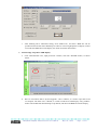
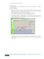
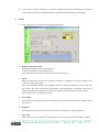
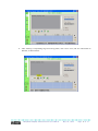
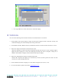
DispTool Display Control Tool User Manual DispTool display control tool uses VC6.0 to compile program. There is no need to install for use, and don’t change the configuration of the user computer. Apply multi-thread technology, and efficiently support various communications such as serial port and Ethernet. Using UNICODE multi-language technology compiles source code, support any languages all over the world, can work on the any language Windows platform. BMP picture control with the independent intellectual property makes the interface more beautiful and diversified. Characteristics ¾ ¾ ¾ ¾ ¾ ¾ ¾ ¾ ¾ ¾ ¾ ¾ ¾ ¾ Support various communication modes such as Ethernet, serial port, USB interface and RDS wireless. Industry level 10base-T Ethernet interface, compatible with 100M/1000M/10G networks. Support TXT text file, BMP picture file, JPG picture, GIF animated cartoon file and GSV form file. Support GB and BIG5 internal code, and at the same time support various simplified Chinese and traditional Chinese dot matrix fonts such as 16×16, 24×24, and 32×32. The maximum of file capacity is 64KB. Can increase and replace display content at will, and adjust display brightness, circulation mode, display speed, and stay time etc. Support clock display, and can display year, month, day, hour, minute, second, and week. Support time error self-regulation. Support brightness self-regulation, can automatically adjust display brightness according to the surrounding environment. Support various typefaces such as Song typeface, bold face. Display is flexible and diverse. Through control tool user can upgrade display online, which is convenient for operation. Command display window can be used to check each operation command of control tool. User password management realizes the individuation selection of operation. Opened software protocol, user can edit display control tool and change the functions of display by oneself. Installation of Control Tool Software 1) 2) 3) Firstly, we send software and DLL files to users by e-mail. Secondly, users copy all DLL files to the system disk installation catalogue﹨system 32; in general, it is “C:﹨WINDOWS﹨system 32”. Finally, if above-mentioned operations have been finished successfully, software can run normally. DispTool Display Control Tool User Manual May.20, 2009 Page 1 of 17 Operation Instructions 1. General instruction 1) Display connects with computer; at the same time make sure that display has connected up power supply. 2) Open DispTool display control tool, as shown in the following illustration, at the same time select the corresponding operation language interface. 1 2 3 4 5 6 7 8 9 10 11 1. 2. 3. 4. 5. LANGUAGE: select language interface user needs and language type that user wants to send. TEXT: input and send text file. PICTURE: input and send picture file. FORM: reserved for the time being. CLOCK: set time display and display mode; at the same time support temperature, humidity, and luminosity percent display, etc. 6. SETUP: display menu font select (English users can skip over this option directly), circulation mode of display content, character display mode, display brightness, character flow speed, and stay time, etc. 7. ADVANCED: send display arrangement (row*column) setting file and upgrade file. Please input user password “123456”. 8. FOUND: search online device. 9. DISPLAY: simulate picture file. 10. COMMAND: display command window. Users can directly view every operation command of DispTool control tool. Please only select a communication mode when viewing operation command. The first icon at the top left corner is used to lock command window, and makes command window always keep appearing in front of other windows. “CLC” is used to clear commands. DispTool Display Control Tool User Manual May.20, 2009 Page 2 of 17 11. DEBUG: instructions debugging dialog box, which provides convenience for secondary development. 3) 2. Recommended operation procedure: 1. Search online device (Display IP). 2. Send display arrangement (row*column) setting file. Note: need to use DisSetup.exe to produce display arrangement setting file. 3. Send file. 4. Adjust display parameter setup such as brightness, speed, and color etc. 5. For the detailed information, please see below. Find Online Device 1) Select “FOUND” icon, as shown below: 1 1. 2. 3. 4. 2 3 4 5 Icon 1 is “search” button, selecting it can directly find out online device (Display IP). Icon 2 is used to delete online device that has been added to the second table. Icon 3 is “Increase” button. It is used to add online device to the second table. Icon 4 is used to display the IP address of display. After finding out display and adding it to the second table, click this icon and display IP address will appear automatically on display. Note: please make sure that display has been added to the second table is online while operating, i.e. “SELECT” and “ONLINE” are “On”. DispTool Display Control Tool User Manual May.20, 2009 Page 3 of 17 5. 6. 7. 8. 9. Icon 5 is used for full brightness. Clicking this icon will light all LED on display. This function can be used to check whether all LED modules are okay, or not. TCP/IP: Ethernet communication mode. COM: Serial port communication mode. Find the IP range of display: the IP range of display is 1 to 255. When user selects serial port communication mode display control tool only find online device in a certain IP range, for instance, if IP range set by user is 1 to 40, display control tool only find online device in this range. Note: it is must to select display IP range when serial port communication. The IP address of display is 01 in general when user gets it for the first time. There is no need to select display IP range when Ethernet communication. Serial port number selection: select the corresponding serial port number of user computer when user selects serial port communication mode. Indicator light will turn on when serial port number is correct. There is no need to select serial port number when Ethernet communication. 2) Search online device When user selects serial port communication mode please first select “COM” option, then set the IP range of display and serial port number, last clicking icon 1 searches online device. When user selects Ethernet communication mode, please first select “TCP/IP” option, and then clicking icon 1 searches online device. Take the serial port communication mode as illustration here: 3) Increase online device Only first add online device, then we can use display control tool normally. Select the online device that has been searched first, then clicking icon 3 is okay, as shown below: DispTool Display Control Tool User Manual May.20, 2009 Page 4 of 17 4) Modify filename and the IP address of display Double click online device (blue typeface) that has been added to the second table, after flicking out a dialogue box, user can directly modify the IP address of display and filename. After modifying, please click “ALTER” to exit. Note: When one computer controls many pieces of displays that all IP addresses are the same, user must first modify the IP address of display and make sure that each display has different IP address, or computer or converter maybe not working normally. 5) Delete online device Click the online device (blue character) that has been increased, then clicking icon 2 is okay. 6) Attention: After finding the online device, users must first add online device, then control tool can normally control online device. Please make sure that the state of online device is always ON, i.e. SELECT DispTool Display Control Tool User Manual May.20, 2009 Page 5 of 17 and ONLINE are ON, as shown below. If SELECT is OFF, you can click it and it will change to ON, but if ONLINE is OFF, it means that communication failed. 3. Display arrangement (row*column) setup 1) Basic operation procedure: first use DisSetup.exe software to produce display arrangement setup file, and then use DispTool.exe display control tool to send display arrangement setup file to LED display screen. 2) Use DisSetup.exe software to produce display arrangement setup file a. open DisSetup.exe and select the corresponding parameter, as shown below. b. “Startup LOGO” is used to set startup logo and the time that displays logo, as shown below. Gray Scales can adjust logo color; X and Y direction can adjust the position of logo on display. DispTool Display Control Tool User Manual May.20, 2009 Page 6 of 17 c. 3) After finishing above mentioned setting, click “Make File”, and then a HSD file will be produced in the file that stores DisSetup.exe software. Last using DispTool.exe display control tool sends this HSD file to LED display. See under for further information. Send arrange setup file to LED display. a. click “ADVANCED” icon, input password “123456”, and click “ENTER” button, as shown below. b. there are two buttons below “System Upgrade”. One is “OPEN”, it is used to open files saved on computer. The other one is “SEND”, it is used to send file to LED display. Using “OPEN” button selects HSD file that DisSetup.exe produced, and then send HSD file to LED display. DispTool Display Control Tool User Manual May.20, 2009 Page 7 of 17 4. Send Text file 1) Select “TXT” icon, as shown below: 1 2 3 4 5 6 2) Instruction of icon: Icon 1 is “New Text File”, it is used to clear all display contents in the textbox. Icon 2 is “OPEN” icon used to open text file saved in computer. Icon 3 is “SAVE” icon used to save display contents in the textbox of control tool as TXT file. Icon 4 is “Increase” icon. Increase new messages on the basis of old messages. Icon 5 is “Replace” icon. Replace old message with new message. Icon 6 is “SEND” icon. 3) Can directly input display contents in the textbox of control tool, as shown below: DispTool Display Control Tool User Manual May.20, 2009 Page 8 of 17 4) Also can use icon 2 to open text file saved in computer, as shown below: 5) Send file Directly click icon 6 after inputting display contents in the textbox of control tool. Attention: Please make sure that the state of online device is always ON, i.e. SELECT and ONLINE are ON, as shown below. If SELECT is OFF, you can click it and it will change to ON, but if ONLINE is OFF, it means that communication failed. 6) Increase and replace file “Increase” means that increase a new file behind old information running on the display. Method of increasing: after inputting display contents in the textbox of control tool, click “Increase” icon, then clicking “SEND” icon is okay. “Replace” means that cancel completely all old files in the display and replace them with a new file. Method of replacing: after inputting display contents in the textbox of control tool, click “Replace” DispTool Display Control Tool User Manual May.20, 2009 Page 9 of 17 icon, then clicking “SEND” icon is okay. 7) Other instructions Internal code mode: only support languages and character that the character library of display control board supports. Support more languages: 1. Support any languages and symbols. After selecting “LATTICE”, can directly input any language in the textbox of display control tool, and then send them to LED display. Note: please select the correct typeface before sending message. 2. Support large-screen display, users can select 16x16, 24x24, and 32x32 fonts. 3. Can support Song typeface, boldface, Roman, Script, Modern, and so on. 4. After selecting “LATTICE”, if LED display is two-color display, users can use Color Edit button to adjust the color of display information. Method of operation: first input text, and then click Color Edit button, as show below. Attention: users can select any color within the color of LED display, as shown below. Method of operation: first choose the corresponding character, and then click color button shown below. DispTool Display Control Tool User Manual May.20, 2009 Page 10 of 17 5. Send picture file 1) Click picture advertisement icon “PICTURE”, as shown below: 2) Input picture file: click “OPEN” icon and choose a picture file saved in users’ computer. 3) Operating methods increasing, sending, and replacing picture file are the same as the operating methods of the text file. 4) “Length” and “width” are used to simulate display effect according to the practical size of display. (The icon in the bottom right hand corner of control tool is used to simulate the display effect of advertisement.) In fact, the length and width of display is identical with the pixel of display, for example, the pixel of display is 16×40, namely, the length of display is 40, and the width of display is 16. DispTool Display Control Tool User Manual May.20, 2009 Page 11 of 17 5) “X” means x coordinates and “Y” means y coordinates. X coordinates and y coordinates can adjust the position of picture on the display 6) “Gray” is gray level. This control tool supports color pictures and monochrome pictures and has the function switching color picture to monochrome picture; users can adjust switching value of the black and white color through pulling scroll bar. 6. Form Display This function is reserved at present. 7. Clock Management 1) Click “CLOCK” icon, as shown in the following illustration: 1 2) Attention: icon 1 is “UPDATE” icon. After finishing setting, please click it. 3) Display Date: display time and date between the display contents. 4) 12-hour: 12-hour time system. 5) 24-hour: 24-hour time system. 6) Clock Mode: 8 kinds of clock modes can be chosen. 7) Error Time: -9 to+9. For example, if users choose -9, software will automatically decrease 9 seconds on the basis of current time after a week, and if users choose +9, software will automatically increase 9 seconds on the basis of current time after a week, the rest may be deduced by analogy. DispTool Display Control Tool User Manual May.20, 2009 Page 12 of 17 8) 8. If users want to display temperature percentage, humidity percentage, and luminosity percentage on the display first have to install thermometer, hygrometer, and photometer on the display. SETUP 1) Click “SETUP” icon, as shown in the following illustration: 2) Display Screen Menu Font: Simplified: simplified Chinese character font. Complex: traditional Chinese character font. Note: English users can skip over this function for the time being. 3) Mode: ORD: the information that has been inputted successfully is displayed circularly according to the sequence of information input. REP: the information that has been inputted currently is displayed repetitively, at the same time don’t delete the other advertisement information, and advertisement information still will be displayed circularly according to the sequence of information input when users choose “ORD”. RAN: display mode is decided by software. 4) Auto-adjust Automatically adjust display brightness according to the surrounding environment changes within 0 to 9 levels. 5) Brightness The adjustable range is from 0 to 9 levels. The level is the higher, the stronger brightness. 6) Stay Time Many kinds of time stay modes. This function decides the time interval between display contents. DispTool Display Control Tool User Manual May.20, 2009 Page 13 of 17 7) Speed The adjustable range is from 0 to 9 levels. The level is the higher, the faster speed. 8) Display Screen Color When display screen is a two-color display screen, users can change the display color of display screen through choosing corresponding options. 9) Characters Mode Left: display information flows out of display screen from right to left. Right: display information flows out of display screen from left to right. Stop: display information appears on the display statically. UP: display information flows out of display screen from the bottom up. Down: display information flows out of display screen from the top down. From up: display information flows out of display screen from the bottom up through composing characters one by one. From down: display information flows out of display screen from top down through composing characters one by one. Snow: display information is displayed randomly through composing characters one bye one at will. Random: above-mentioned modes are displayed randomly. 10) 1 Color After clicking “1 Color”, 2 Color will appear. Kindly note that user should choose “2 Color” when user uses two color display. 11) After finishing operation, please click “UPDATE” icon. 9. Upgrade Display System Upgrade: upgrade display through sending upgrade file. The method of upgrade: first click “OPEN” icon, then choose upgrade file saved in computer, last clicking “SEND” icon is okay. Please refer to page 7 of this manual. Note: a) Password only takes effect at this interface. Users must input correct password before operating other functions on this interface. b) After finishing operation, please click the corresponding “ENTER” icon. c) Please click online product before operating. DispTool Display Control Tool User Manual May.20, 2009 Page 14 of 17 Using U Disk Changes Display Information 1. When user wants to display 16×16 characters, directly using the notepad of computer edits TXT text file first, then copy TXT file to U disk, last connect U disk with display. 2. When user wants to display 24×24 or 32×32 characters, the operating method is as follows (the following operating method applies to 16×16 characters also). a. Open DISTOOL display control tool, then select “TXT” icon, as shown below: b. Directly input display information in the textbox, then select “LATTICE”, as shown below. c. After selecting “LATTICE”, choose the corresponding large font in the “Font Volume Select”, and choose the corresponding typeface in the “Font Select”, as shown below. DispTool Display Control Tool User Manual May.20, 2009 Page 15 of 17 d. After selecting corresponding large font and typeface, click “Save” icon, and save information as DIP file, as shown below. DispTool Display Control Tool User Manual May.20, 2009 Page 16 of 17 e. Last, copy DIP file to U disk, and connect U disk with display. Troubleshooting User can check following items when PC terminal tool communication is not normal. 1. Check display screen power supply to make sure that power supply has been connected correctly, and confirm that display can work normally before using control tool. 2. Check RS232 interface, RS485 interface, and Ethernet interface to make sure that connection is correct 3. When user adopts serial interface communication mode: Check the COM port to make sure that the COM port that has been chosen is correct. Indicator light is lighted up when COM port is correct and COM port should be the same as computer’ COM port. In addition, the IP address of display must be within the IP range of display. 4. When user adopts Ethernet interface communication mode: Confirm that computer and display have connected up converter, besides; please first make sure that converter can work normally before use. 5. Check whether the models of display, row and column arrangement are correct, or not. 6. For more information, please send email to [email protected] . DispTool Display Control Tool User Manual May.20, 2009 Page 17 of 17