1
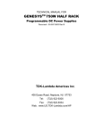
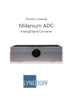
5.1 DTS/Dolby Digital AC-3 Audio Decoder DA32UD User Manual Features ¾ ¾ ¾ ¾ ¾ ¾ ¾ ¾ ¾ ¾ ¾ ¾ ¾ ¾ Adopt CS4926 series audio DSP, CS8415 96KHz digital receiver, 96 KHz/24bit ADC and DAC. Support Dolby digital, Dolby pro-logic, DTS, and so on, with many kinds of listening modes and sound field effect playbacks. Analog audio output, can select different low-pass filter circuits by itself so as to realize different effects. Full-range bandwidth (20Hz to 20K Hz), user can adjust bandwidth through low-pass filter. Built-in analog input mute, when there is no analog signal, the muting process will automatically go on, there is no need to connect detection circuit outside. Digital and analog ground wires are independent, which lowers the requirement of motherboard PCB LAYOUT and gets better performance. Provide mute control signal output and use hardware to mute directly. STL212 MCU can upgrade directly program online. Users can get new program on Internet when necessary, which provides convenience for debugging and maintenance. Several universal output ports, it is okay to use built-in CPU to complete whole machine functions. Use I2C slave interface to connect user host, and it is okay to use existing I2C interface without adding additional interface. I2C interface can be used with another I2C device in parallel. DA32UD is the same as many I2C devices such as 24C01 and so on, and it’s easy for users to do secondary development. I2C communication has TNT interrupt output port, user host can read corresponding data when TNT changes, which reduces the holding time of user host communication. Built in memory space with 60 bytes, its function is the same as 24C01, and there is no need for users to use memory chips such as 24C01, 93C46 and so on any more. Directly mounted on the board as an integrated product with audio board, which improves the traditional connection of decoder and enhances the reliability and appearance of product. DA32UD and DA32UQ are Pin-compatible Products DA32UD and DA32UQ can be replaced each other, their differences are as follows: DA32UQ’s price is lower than the price of DA32UD. The bass management of DA32UD is implemented by inner bass software, and it is acceptable that there are many kinds of bass configuration at the same time, while the bass management of DA32UQ is implemented by hardware. DA32UD has internal EFFECT sound field effects, with many kinds of DSP effect options; DA32UQ is only external. Hard & Soft Technology Co., LTD. http://www.HSAV.com Address: second floor, No.199, Longyin 2nd Road, Xixiang, Shenzhen, China TEL: 86-0755-27951479 27950879 FAX: 86-0755-27950879-213 Business contact:[email protected] Technology support:[email protected] DA32UD User Manual hsavd218.pdf Front side Dec.10, 2009 Rear side Application Fields √ Digital audio decoder or analog audio decoder. √ AV reception Power amplifier. √ Multi-channel multimedia active sound box with power supply and decoding. Ground Wire Instructions AGND and GND are not connected inside DA32UD, and need to be connected on the user board. If +5V ground wire and analog ground wire are not connected at the power supply terminal, connection point should be close to the DA32UD pins. GND connects with the ground wire of metal case, which makes the resistance of ground wire lower so as to get better effect. If not, connecting at power supply is also acceptable, while the position close to DA32UD is preferable for a better effect. DA32UD Dimension Diagram Front side Rear side DA32UD Board thickness 1.6mm PCB installation diagram © 2002-2010 Hard & Soft Technology Co., LTD. User mainboard PCB http://www.HSAV.com Page 2 of 13 DA32UD User Manual Pins Instructions 1. 2. 3. 4. 5. 6. 7. 8. 9. 10. 11. 12. 13. 14. 15. 16. 17. 18. 19. 20. 21. hsavd218.pdf Dec.10, 2009 SCL Serial clock output port of controlling external volume IC, which is multiplexed with the clock of debugging downloading. SDA Serial data output port of controlling external volume IC, which is multiplexed with the clock of debugging downloading. PB3 Universal input or output port. PB2 Universal input or output port, SCL port of I2C communication port. It is infrared remote control reception input in the general application. PB1 Universal input or output port, SDA port of I2C communication port. PB0 Empty pin. +5V Power supply +5V input. GND Digital ground wire input and output. RX3 The third group of digital input. RX2 The second group of digital input. RX1 The first group of digital input. MUTE Mute control signal output. Output high level when mute takes effect, output low level when the sound works normally. SW Sub woof channel signal output. CE Central channel signal output. SR Surround right channel signal output. SL Surround left channel signal output. FR Front right channel signal output. FL Front left channel signal output. AGND Analog ground wire audio output and power supply input, it does not connect with digital ground, and it is necessary to connect digital ground wire outside. RCH Analog right channel signal input. LCH Analog left channel signal input. Related Technical Files z z z 《I2C Device Development User Manual》---------------------------------------------------------------hsavd107.pdf 《OTG15X Series I2C Software User Manual》---------------------------------------------------------hsavd106.pdf 《ST-991AR5 upgrade device user manual》-------------------------------------------------------------hsavd201.pdf Upgrade Method DA32UD uses DA32UD.AR5 as upgrade file. We will send this upgrade file to user when necessary. Two upgrade methods are as follows: The first: ST-991AR5 adaptor connects computer through serial interface, and at the same time connects product; connect power and upgrade product. The second: first download upgrade file to ST-991AR5 adaptor, and then directly use adaptor to upgrade product without connecting computer. For details, please refer to ST-991AR5 upgrade device user manual hsavd201.pdf © 2002-2010 Hard & Soft Technology Co., LTD. http://www.HSAV.com Page 3 of 13 DA32UD User Manual Audio Processing Instructions hsavd218.pdf Dec.10, 2009 Positive and negative power supply is the best choice for the sake of a good effect. Certainly single power supply is acceptable also, in this case, operational amplifier positive input connects with 1/2 power supply as shown below. If there is no requirement for the sound, operational amplifier is not required and resistor and capacitor filter can be directly used as shown below, but signal output range and high frequency are not good. R2 15K Audio output R5 4K7 R2 4K7 C1 4 C5 102 6 5 R5 C2 10U LCH 10U RCH 7 IC3-2 NE4570 75R 8 +6V-+24V 221 + 10U - C2 R2 15K C2 C5 104 10U R5 4K7 R5 4K7 C1 C5 102 R5 2 1K 3 221 1 + C12 - C4 470U IC3-1 NE4570 R5 1K C4 100U C5 104 The Low-pass filter applying single power supply Audio output C12 10U R9 LCH 4K7 C13 102 C2 10U R5 RCH 4K7 C13 102 Simple passive low-pass filter © 2002-2010 Hard & Soft Technology Co., LTD. http://www.HSAV.com Page 4 of 13 DA32UD User Manual Electrical Specification Items +5V power supply voltage hsavd218.pdf Dec.10, 2009 Minimum +4.6V Typical +5V Maximum +5.5V 350mA 360mA 380mA Digital RX input 0.1V(P-P) 0.5V(P-P) 1.0V(P-P) Analog input effective detection level 0.8 Vrms -- -- Analog signal output @0dB 0.8Vrms 0.9Vrms 1.1Vrms Output noise level(digital input CCIR/ARM) 50uV 58uV(S/N = 93dB) 76uV Output noise level ( digital input, not weighted) Output noise level ( analog input CCTR/ARM) Output noise level ( analog input, not weighted) Frequency response(20Hz-20KHz) 560uV 600uV 800uV 70uV 76uV(S/N = 90dB) 80uV 600uV 700uV 800uV -- +/-0.5dB -- +5V working current Software Development Instruction DA32UD provides user host customization function, and can complete whole machine functions alone. If user product has MCU, it is okay to select I2C communication. If two bytes form 16-bit parameter, the first byte is low bit and the second byte is high bit. If four bytes form 32-bit parameter, the first byte is low bit and the fourth byte is high bit. 0xnn means the described value is uncertain, it may be any values, but its value is within range fixed originally, for instance, instruction length is 2 to 137. B7 means the seventh bit of byte, B6 means the sixth bit of byte, and the rest may be deduced by analogy. I2C address that user host writes DA32UD is 0x5e, i.e. 01011110B. I2C address that user host reads DA32UD is 0x5f, i.e. 01011111B. The length of register is 8 bits in general, and user host only needs one byte for read and write. Another registers that mark byte length need several bytes for read and write, should do multibyte read and write according to need. DA32UD write register diagram: Device address Register Start (write) address Write data 0 DA32UD read register diagram: Device address Register address waiting Start (write) for being read Start © 2002-2010 Device address (read) Hard & Soft Technology Co., LTD. Read data 0 Write data X (when multibyte) End End Read data X (when multibyte) http://www.HSAV.com End Page 5 of 13 DA32UD User Manual hsavd218.pdf Dec.10, 2009 First use the device address of write to write register address waiting for being read, and then use the device address of read to read corresponding data. Need to receive the ninth ACK bit when write each byte including data and address for I2C, ACK bit is 0 outputted by DA32UD. User host can know if DA32UD is working normally according to ACK. Need to send the ninth ACK bit when read each byte for I2C, ACK bit is 0 outputted by user host, but the last byte needs to send the ninth NAK bit, NAK bit is 1 outputted by user host. I2C Communication User Host Instructions set Address Name 0x00 INTCLR 0x01 INTRD 0x02 INTENA 0x03 POWERON 0x04 DIGITINFO 0x05 CHINFO 0x06 ANASIGNAL 0x07 SFREQFREG 0x08 MUTE © 2002-2010 Description Clear interrupt register (write only) Interrupt number: INT0=1, DA32UD initialization, guarantee that user host and DA32UD connect power synchronously. INT1=1, digital signal input format change, interrupt needs to read “DIGIINFO” register. INT2=1, analogue signal input change interrupt, need to read “ANASIGNAL” register. INT3 to INT7, reserved. Read interrupt register (read only ) Interrupt number is the same as clear interrupt register. Attention: please clear corresponding interrupt number after read, or interrupt will go on without stop. Register writes 1 to clear corresponding interrupt. Interrupt enable register (write only) Set corresponding interrupt enable. DA32UD will generate corresponding interrupt and lower INT pin when status changes. User host needs to detect INT pin and read interrupt value and do corresponding treatment. Interrupt number and read/write interrupt register are corresponding. Allow corresponding interrupt when corresponding bit is 1, and forbid corresponding interrupt when corresponding bit is 0. Digital signal input format indication (read only) B3 is DTS digital signal input. B2 is Dolby digital AC3 signal input. B1 is PCM digital signal input. B0 means that there is no signal input. Dolby digital or DTS input channel information (read only) 0x00 is 1+1, 0x10 is 1/0, 0x20 is 2/0, 0x30 is 3/0, 0x40 is 2/1, 0x50 is 3/1, 0x60 is 2/2, 0x70 is 3/2, 0x90 is 4/2, 0xa0 is 3/2+1, 0xb0 is 4/2, 0xc0 is 5/2, 0xd0 is 4/4, and 0xe0 is 5/3. Analogue signal input level indication (read only) 0 is analogue signal input level, and more than 6mV. 1 is analogue signal input level, and less than 6mV. Enter into mute state and there is no sound output. Sampling frequency (read only) (reserved) AC-3: 0x00/48K; 0x01/44.1K; 0x02/32K; DTS: 0x0f /Err,0x04/8K,0x05/16K,0x02/32K,0x06/64K,0x07/128K; 0x08/11.025K, 0x09/22.05K, 0x01/44.1K, 0x0a /88.2K, 0x0b /176.4K; 0x0c /12K,0x0d /24K,0x00/48K,0x03/96K,0x0e /192K. Control mute pin (write only) Low level when B0 is 1. High level when B0 is 0. Note: output high level when mute takes effect and output low level when the sound works normally Hard & Soft Technology Co., LTD. http://www.HSAV.com Page 6 of 13 DA32UD User Manual Address Name 0x0a INPUTSEL hsavd218.pdf Dec.10, 2009 Description Input port selection (write only) Select analogue signal input when B7 is 1. Select digital input when B7 is 0. B1 to B0 is to select different digital ports: 0x00 means inputting from RX1; 0x01means inputting from RX2; 0x02 means inputting from RX3. Listening mode selection (write only) Select TEST TONE function When B7 is 1. B3 to B0 is corresponding channel selection, they are the same as sound channel selection codes, there is no sound when selecting 0x08, but enter into TEST TONE state. Sending 2.1CH OR 5.1CH exits from TEST TONE. 0x0b LISTMODE 0x0c SPKCONFIG 0x0d DNYCOMP 0x0e DSPMODE 0x0f VOLCTRL 0x10 to 0x15 DLTIME 0x80 to 0x1d 0xc0 to 0xdd Select standard listening mode when B7 is 0 and B6 is 0. B2 to B0 is to select different effects: 0x00 is automation mode, if input is Dolby digital AC-3 (2.1sound channel), listening mode is AC-3 (2.1sound channel); if input is Dolby digital AC-3 (5.1sound channel), and listening mode is Dolby digital AC-3 (5.1sound channel). 0x01 is stereo. 0x02 is Dolby Pro Logic mode (5.1CH). Speaker setup (write only) Note: big speaker means low, medium, and high bandwidth; small speaker means medium and high bandwidth. It is small speaker when B0 is 0, and it is big speaker when B0 is1. Dolby digital dynamic compression (write only) Only when input digital data rate is Dolby digital AC-3, it is effective. 0x00 is normal playback without compression, the rest are dynamic compression playback. DSP effect setup (write only) B7 is 0. when PCM digital and analogue input, B2 to B0 is to select different DSP effects: 0x00 is HALL, 0x01 is CHURCH, 0x02 is DISCO, 0x03 is THEATER, 0x04 is LIVE, 0x05 is MOVIE, 0x06 is MUSIC, 0x07 is SIMULATE, and 0x08 is exit. Volume setup (write only) 0x00 is minimum volume 0dB, 0x3f is maximum volume 63dB。 Channel delay adjustment (write only) 0x10 is CEDLTME, 0x11 is SLDLTME, and 0x12 is SRDLTIME. Central delay writes 0 to 15, it is 0 to15ms in Dolby digital mode. Surround delay writes 0 to 15, it is 0 to 15ms in DTS and Dolby Digital mode, and it is 15ms to 30ms in Dolby Pro Logic mode. Note: it is effective only when listening mode is digital automation or Dolby Pro Logic mode. MEMORYWR FLASH memory space with power-failed memory write MEMORYRD FLASH memory space with power-failed memory read Attention: above text is relevant information when DA32UD adopts I2C communication, and following text is relevant information when DA32UD adopts SSB communication. © 2002-2010 Hard & Soft Technology Co., LTD. http://www.HSAV.com Page 7 of 13 DA32UD User Manual User Host Write Instructions Address Name 0x01 Input port selection 0x02 Listening mode switch hsavd218.pdf Dec.10, 2009 Description Select analogue signal input when B7 is 1. Select digital input when B7 is 0. Select different digital ports from B1 to B0. 0x 00 is inputted from digital RX1. 0x 01 is inputted from digital RX2. 0x 10 is inputted from digital RX3 Select TEST TONE function When B7 is 1. B3 to B0 are corresponding channel selections, they are the same as sound channel selection codes, there is no sound when selecting 0x08, but enter into TEST TONE state. Select standard listening mode when B7 is 0 and B6 is 0. B2 to B0 is to select different effect: 0x00 is digital automation, if input is Dolby digital AC-3, listening mode is AC-3 DIGITAL; if input is DTS, and listening mode is DTS DIGITAL. 0x01 is stereo. 0x02 is Dolby Pro Logic mode. Attention: big speaker means low, medium, and high bandwidth; small speaker means medium and high bandwidth. B7 is back speaker selection, 1 is big speaker. ( DA32UD is unavailable) B6 is surround speaker selection, 1 is big speaker. B5 is central speaker selection, 1 is big speaker. B4 is front speaker selection, 1 is big speaker, B3 is super bass channel setting selection, 1 means there is no installation. B2 is back channel setting selection, 1means there is no installation. ( DA32UD is unavailable) B1 is surround channel setting selection, 1 means there is no installation. B0 is central channel setting selection 1 means there is no installation. 0x03 Speaker setup (0x00 is standard configuration 1, all are small speaker and with super bass) 0x04 Dolby digital dynamic compression (0x00 is without compression) Only when input digital data rate is Dolby digital AC-3, it is effective. 0x00 is normal playback without compression, the rest are dynamic compression playback. 0x08 DSP B7 is 0. B2 to B0 is to select different DSP EFFECT. 0x00 is HALL;0x01 is CHURCH; 0x02 is DISCO; 0x03 is THEATER; 0x04 is LIVE; 0x05 is MOVIE; 0x06 is MUSIC; 0x07 is SIMULATE. 0x20 Volume control 0x00 is 0dB, i.e. minimum volume; 0x50 is maximum volume, i.e. 80dB. Channel delay adjustment 0x10 is FL channel, 0x11 is CE channel and so on, and they are corresponding to the codes of channel selection. (DA32UD only supports 0x11 central and 0x13 surround channels).Central delay writes 0 to 5. It is 0 to 5ms when Dolby Digital mode. Surround delay writes 0 to 15. It is 0 to 15ms when DTS and Dolby Digital mode, it is 15ms to 30ms actually when Dolby Pro Logic mode. Note: it is effective only when Listening mode is digital automation or Dolby Pro Logic mode. 0x10 to 0x17 © 2002-2010 Hard & Soft Technology Co., LTD. http://www.HSAV.com Page 8 of 13 hsavd218.pdf DA32UD User Manual User Host Interrupt and Read Instructions Address Name 0x7f Clear interrupt 0x80 signal input status Dec.10, 2009 Description Write 0x80 to clear SIN application interrupt action caused by 0x80. In general, write after read is correct so as to clear interrupt. B6 to B4 is Dolby digital or DTS input source code format. 0x00 is 1+1,0x01 is 1/0,0x02 is 2/0,0x03 is 3/0,0x04 is 2/1,0x05 is 3/1,0x06 is 2/2,0x07 is 3/2. B0 means there is not signal input. B1 means PCM signal input. B2 means Dolby digital AC3 signal input. B3 means DTS digital signal input. Simple Serial Bus Instructions Simple Serial Bus is SSB for short, it is composed of three lines, SCK bit clock, and SDD bit digital and SIN address latch and interrupt. All three lines of SSB are high level when idle. Generally adopt the port of open-drain structure, for instance 8051 series ports, raise level through pull-up resistor. If use ports with input and output selection, the port will be chosen as input when idle and output is high. Only when output is low level the port will be chosen as output, which is convenient for program processing. SSB must adapt to ports from 2.5V to 5.0V. If connection wire between master and slave is too long, pull-up resistor can be added or capacitors from several P to hundreds of P can be connected with ground wire to filter disturbance from the circuit. SSB adopts SCK as serial synchronous clock outputted by the communication master. SDD is serial synchronous data and it is bi-directional data. SIN is interrupt port slave applies from master and address latch signal from master to slave, it is low when master is delivering address. SSB is composed of address, data and acknowledge signal, among them, address is outputted by master and inputted by slave unchangeably. Data is bi-directional transmission, it is output when master is writing register and it is input when master is reading register. Acknowledge signal can confirm if the transmission is correct, and it is initiated by slave, and its value is fixed to the contrary value of the last data bite. If master doesn’t receive correct acknowledge signal, there is need to be resent. In the transmission of SSB, low bit outputs first. During the transmission of address signal,master has to put SIN low, while in the process of data and acknowledge transmission must make SIN high. There are two types of SSB: low speed type and high-speed type, two kinds of control modes are the same. The communication speed of low type is 33Kbps, namely, every SCK time is 30US (one falling margin to next falling margin). The communication speed of high type is 1Mbps, namely, every SCK time is 1us. SSB address is composed of 4 to 8 bytes. According to different address bits, there are SSB4, i.e. 4-bit SSB, SSB8, i.e. 16-bit SSB, and so on. DA32UD adopts SSB8 low speed bus with 8-bit address and 8-bit data. © 2002-2010 Hard & Soft Technology Co., LTD. http://www.HSAV.com Page 9 of 13 DA32UD User Manual Master (user host) hsavd218.pdf SCK PB2 SDD PB1 SIN PB0 Dec.10, 2009 Slave SSB master (user host) and slave connection diagram SSB8 Low-speed Bus Instructions In the process of communication, master is MCU used by user host and called user host for short. Slave is DSP used by DA32UD and called DA32UD for short. Suggest using the port without input and output control port to communicate with. If user host has input and output direction selections, select output only when output low level so as to automatically adapt to SSB level. SSB8 Bus Writ Register Time sequence Instructions DA32UD uses the low speed bus of SSB8; has 16 registers aggregately, address length is 8 bits, and data length is 8 bits 1 byte. When the user host writes register, 8-bit address should be written first and low bit should be outputted first. The transmission time sequence of write register is as follows: 1. Lower SIN. 2. Output A0 bit of the address first. 3. Lower SCK and delay time to a corresponding time (low speed is 15us, high speed is 0.5us). 4. Raise SCK and delay time to a corresponding time (low speed is 15us, high speed is 0.5us). 5. Output A1 bit of the address. 6. Repeat 3 to 5 until finishing A7 bit. 7. Raise SIN. 8. Output D0 bit and repeat SCK action until finishing D7 bit. 9. Raise SDD and turn SDD into input, and ready to receive acknowledge bit. 10. Lower SCK and delay time, then slave will output opposite code of D7 as acknowledge signal. 11. Read SDD after raising SCK and delaying time, if result is opposite, it means the data is read successfully. 12. Lower SCK and delay time, this moment slave outputs SDD as high. 13. After raising SCK and delaying time, write register is over 14. If write is not successful, rewrite until commands are written correctly. 15. Attention: No matter SIN is high or low, when SCK turns low for the first time, DA32UD will output SIN as high. If there is wrong with write and read, when the bus is idle slave will lower SIN again so as to send interrupt signals to master. © 2002-2010 Hard & Soft Technology Co., LTD. http://www.HSAV.com Page 10 of 13 DA32UD User Manual hsavd218.pdf Dec.10, 2009 SCK SDD A0 A3 A1 D1 D0 D7 ACK SIN User host write register command SSB Bus Read Register Time sequence Instructions DA32UD uses the low speed bus of SSB8; has 16 registers in all, address length is 8 bits, and data length is 8 bits 1 byte. Master can read register when lowering SIN, or can read register at any time; after reading 0x80 correctly, DA32UD doesn’t automatically clear SIN state, must write 0x80 at 0x7f address so as to clear interrupt. Master first writes register waiting for being read. The transmission time sequence of is as follows: 1. Lower SIN. 2. Output A0 bit of the address first. 3. Lower SCK and delay time to a corresponding time (low speed is 15us, high speed is 0.5us). 4. Raise SCK and delay time to a corresponding time (low speed is 15us, high speed is 0.5us). 5. Output A1 bit of the address. 6. Repeat 2 to 5 until finishing A7 bit. 7. Output SDD, turn SDD into input, and ready to receive data. 8. Lower SCK and delay time, this moment slave sends DO to SDD. 9. Raise SDD, read DO bit. 10. Repeat 8 to 9 until receiving D7 completely. 11. Lower SCK and delay time, then slave will output the opposite code of D7 as acknowledge signal 12. After raising SCK and delaying time, if result is opposite, it means the data is read successfully. 13. Lower SCK and delay time, this moment slave outputs SDD as high. 14. After raising SCK high and delaying time, read register is over. 15. If read is not correct, reread until commands are read correctly. 16. Attention: No matter SIN is high or low, when SCK turns low for the first time, DA32UD will output SIN as high. If there is wrong with write and read, when the bus is idle slave will lower SIN again so as to send interrupt signals to master. © 2002-2010 Hard & Soft Technology Co., LTD. http://www.HSAV.com Page 11 of 13 DA32UD User Manual hsavd218.pdf Dec.10, 2009 SCK SDD A0 A1 A3 D0 D1 D7 ACK SIN User host read register command Multimedia No.1 Source Code and SSB Routine Instructions Download “Da32uq_ud communication routine. ZIP” document. After decompressing, directly run F71.bat to generate HEX, BIN and AR5 burning file. Among the example, ROM part has been used is less than 4 K, and RAM part is less than 128bytes, can be burned to AT89C51AK or single-chip that is compatible with AT89C51AK. a) F71_SSB.c can be directly transplanted to user host. 1) Documents permitting to be edited and modified are as follows: F71.bat Batch document, directly run F71.bat to generate HEX and BIN files. F71_main.c Master module document, main function, main circulation and interrupt processing. F71_sub.c Slave module document, key-press processing, initialization and TM1628 display control. F71_aud.c Audio processing module document, audio and PT2258 volume control. F71_ssb.c SSB module document, it can be directly transplanted to user host. F71_main.h Head file, all variables are defined in this document. 2) © 2002-2010 F71_main.lin Connection configuration document. Documents not permitting to be edited or modified are as follows: Da32uduq.mak and da32uduq.vcp MSVC project document F71_main.hex、F71_main.bin 、F71_main.Ar5 Generated burning document. Hard & Soft Technology Co., LTD. http://www.HSAV.com Page 12 of 13 DA32UD User Manual hsavd218.pdf b) LIB file folder is devices header file and library file. c) BIN file folder is executable files and related tools. TM1628 Dec.10, 2009 CLK P2.5 P16 SCK DAT P2.6 P15 SDD P14 SIN STB P2.7 DA32UQ AT89C51 PT2258 SCL P3.7 SDA P3.6 Multimedia No.1 single-chip machine interface diagram © 2002-2010 Hard & Soft Technology Co., LTD. http://www.HSAV.com Page 13 of 13