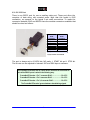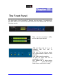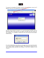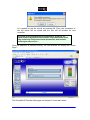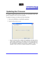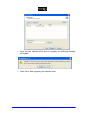
1
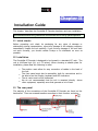
ProntoNet
IP Decoder
User Manual
Ver 2.1.1
Index
Index......................................................................................2
CE Declaration of Compliance ......................................................4
Introduction ............................................................................5
Installation Guide .....................................................................6
II.1 Initial checks ........................................................................6
II.2 Installation...........................................................................6
II.3 The rear panel.......................................................................6
II.3.1 Power .............................................................................7
II.3.2 Ethernet port – the LAN Connector ...........................................8
II.3.3 RS 232 Port .......................................................................9
II.3.4 GPIO Port....................................................................... 10
II.3.4.1. Inputs ......................................................................... 10
II.3.4.2. Outputs....................................................................... 10
II.3.5 Audio interfaces ............................................................... 11
II.3.5.1. Analog audio Outputs ...................................................... 11
II.3.5.2. AES/EBU Interface .......................................................... 11
II.3.6 Microswitches.................................................................. 11
The Front Panel ..................................................................... 12
Remote Control ...................................................................... 13
IV.1 General Configuration ...........................................................
IV.1.1 Ports: ..........................................................................
IV.1.1.1. LAN port: ....................................................................
IV.1.1.2. RS232 Port: .................................................................
IV.1.1.3. SNMP Traps: ................................................................
IV.1.1.4. GPIO Port: ..................................................................
IV.1.2 Audio Output: .................................................................
IV.1.3 System Configuration ........................................................
IV.1.3.1. Exporting / Importing the configuration ................................
IV.1.4 Streaming:.....................................................................
IV.1.4.1. Rx: Reception parameters. ...............................................
IV.1.4.2. Test ..........................................................................
IV.1.4.3. Real Time Monitoring ......................................................
IV.1.5 Phone Book: ...................................................................
IV.1.6 Call Log ........................................................................
16
17
17
18
19
19
22
22
26
26
27
27
30
31
32
IV.2 Controlling the ProntoNet ......................................................
IV.2.1 Making Calls: ..................................................................
IV.2.2 Disconnecting the Line: .....................................................
IV.2.3 Line Status: ...................................................................
33
33
34
34
Prontonet IP Decoder User Manual v211.doc
2
IV.2.4 Decoder Status: ............................................................... 35
IV.3 Alarms .............................................................................
IV.3.1 Selecting Alarms ..............................................................
IV.3.2 Monitoring Alarms ............................................................
IV.3.3 Alarms History ................................................................
36
36
37
37
How does the ProntoNet IP Decoder work?...................................39
IV.4 About how the Decoder works and automatic searching ................... 39
IV.5 The ProntoNet IP Decoder operation modes.................................. 40
IV.5.1 UNICAST communications ................................................... 40
IV.5.1.1. Establishing a UNICAST connection from the ProntoNet IP Decoder 40
IV.5.1.2. Establishing a MULTICAST Rx communication from the ProntoNet IP
Decoder .............................................................................. 41
IV.6 About the Ancillary Data ........................................................ 42
Technical Specifications .......................................................... 43
V.1 Audio Interfaces .................................................................. 43
V.2 Compression algorithms (Decoding) ............................................ 43
V.2.1 BANDWIDTH (KHz) ............................................................ 44
Communications Ports................................................................
LAN port..............................................................................
GPIO Port ............................................................................
RS232 Port ...........................................................................
45
45
45
45
V.3 Power Supply ...................................................................... 46
Main..................................................................................... 46
Secondary (Optional) ................................................................. 46
V.4 Dimensions and Weight .......................................................... 46
V.5 Environment ....................................................................... 46
Disconnection Codes ............................................................... 47
Updating the firmware ............................................................ 48
Prontonet IP Decoder User Manual v211.doc
3
CE Declaration of Compliance
Procesamiento Digital y Sistemas S.L., hereby declares that ProntoNet IP
Decoder bearing the CE168X parking are in comliance with Electromagnetic
Compatibility Directive (89/336/EEC), and the Low Voltage Directive (72/23/EEC)
of the European Union.
A “Declaration of conformity” for ProntoNet IP Decoder is available on file at
Prodys offices in Spain. To obtain this information, contact with
[email protected].
CAUTION
ProntoNet IP Decoder uses a Lithium battery.
Danger of explosion if battery is incorrectly replaced. Replace only with the same
or equivalent type recommended by the manufacturer. Dispose of used batteries
according to the manufacturers instructions.
Your product is designed and manufactured with high quality
materials
and components, which can be recycled and reused.
When this crossed-out wheeled bin symbol with black bar underneath
is attached to a product it means that product is covered by the
European Directive 2002/96/EC.
Please, inform yourself about the local separate collection system for
electrical and electronic products.
Please act according to your local rules and do not dispose of your old
products with your normal household waste. The correct disposal of
your old product will help prevent potential negative consequences for
the environment and human health.
Prontonet IP Decoder User Manual v211.doc
4
Chapter I
Introduction
ProntoNet IP Decoder supplements the PRODYS IP range of audio codecs
family. It is based on the features provided in ProntoNet.
ProntoNet IP Decoder is a multi-algorithm stereo audio decoder over IP,
supporting many industry standard coding algorithms such as; G722, MPEG1/2
LayerII, MPEG1/2 LayerIII, MPEG2/4 AAC LC, MPEG4 AAC LD, apt-X
(enhanced and standard) as well as uncompressed linear audio (PCM).
Each ProntoNet IP Decoder fully supports IP (TCP and UDP), connecting via
a 10BaseT/100Base-TX Ethernet port (RJ45 connector). This enables remote
monitoring/configuring and data/audio transportation over data communication
links (LAN, Wan, Internet…).
About this manual
The inform ation is arranged in the following sections:
§
Chapter II – Installation Guide.
This chapter provides hardware requirements and instructions for installing
the ProntoNet IP Decoder unit.
§
Chapter III – The remote control.
ProntoNet IP Decocer can be controlled from a Web Browser. This chapter
describes how to start it and how to use it.
§
Chapter IV – How does the ProntoNet IP Decoder work?
This chapter is a practical guide to help in understanding just how the
ProntoNet IP Decoder unit works under different configurations, especially
the more unusual ones.
§
Appendix A – Technical Specifications.
§
Appendix B – Disconnection Codes.
This appendix describes the meaning of the disconnecting codes showed on
the display.
§
Appendix C – Updating ProntoNet IP Decoder firmware.
Prontonet IP Decoder User Manual v211.doc
5
Chapter II
Installation Guide
This chapter describes the ProntoNet IP Decoder hardware and user installation.
The installation and servicing instructions in this manual are for use by qualified personal.
II.1 Initial checks
Before unpacking unit check its packaging for any signs of damage or
mishandling during transportation, report any damage to the shipping company
immediately. Unpack the unit carefully, if you find any damage or the unit does
not work correctly, you should contact Prodys or its distributor as soon as
possible.
II.2 Installation
The ProntoNet IP Decoder is designed to be housed in a standard 19” rack. The
unit is 44.45mm high (1U, or 1.75 inches). When choosing a suitable place for
installation, please bear the following in mind:
§
§
§
§
The position must allow for easy connection of cables to the back of
the unit.
The front panel must also be accessible, both for connections and to
be able to see the Display, keyboard and LED indicators.
The air vents must not be obstructed
We do not recommended that the unit is mounted directly above
other equipment, especially ones that generate a lot of heat.
II.3 The rear panel
The majority of the connections of the ProntoNet IP Decoder are found on the
back panel. They are grouped together according to their function, as below:
Prontonet IP Decoder User Manual v211.doc
6
II.3.1 Power
On the back panel you will find the main power inlet. You will also find the main
power switch and the fuse holder. The ProntoNet IP Decoder unit is designed to
take AC universal power, from 100 to 240 VAC with frequency between 50Hz and
60Hz.
You will also find a fuse holder that holds two fuses, one for each phase of input.
When it is necessary to replace either fuse, it is important to make sure that it
complies with the technical specifications outlined below that will ensure
adequate protection.
Fuse requirements:
Fuse type:
Amps
Power
Type T
2A
250V
ATTENTION – CHANGING THE FUSE
Disconnect the power cable BEFORE changing the fuse.
VDC SECONDARY POWER SOURCE
§
THIS IS OPTIONAL AND DOES NOT COME FITTED AS STANDARD. IT
CAN BE 12, 24 OR 48 VDC.
§
The unit will switch automatically from the primary power source to the
back-up power source in the event of a cut in the primary power supply.
Prontonet IP Decoder User Manual v211.doc
7
II.3.2 Ethernet port – the LAN Connector
The LAN socket is an standard 100Base-Tx (10/100 Mbps) Ethernet connection
that takes the typical RJ45 plug. Through this Ethernet port it is possible to
transmit and receive audio, as well as manage the equipment. Next to the
socket there are three LEDs that indicate different states for the connection and
these are very useful in problem-solving situations.
LAN LED’s:
§ Connection to a Hub or Switch
In the majority of cases you can simply connect the unit’s LAN port to your
Ethernet network’s Hub or Switch using an Ethernet cable (CAT5). In this
case you should use a standard ‘straight-through’ Ethernet cable (not a
‘cross-over’ cable). This kind of cable can normally be found in any IT shop.
In any case, this cable is described in more detail below:
§ Connection to a PC
In some cases, such as when you configure the equipment, it is possible
that you will want to connect the unit directly to a PC. In this case the PC
must have a free Ethernet port to connect to and you must use a ‘crossover’ Ethernet cable. Again, any good IT shop will stock these cables. This
time the wiring is as follows:
Prontonet IP Decoder User Manual v211.doc
8
II.3.3 RS 232 Port
There is one RS232 port for use as auxiliary data port. These port allow the
reception of data along with encoded audio. Note that this socket is RJ45
connection, as opposed to the typical 9-pin subD connections. To make the
conversion between RJ45 and RS232 there are modular connectors available that
should be wired as follows:
S-Cluster
RJ45
Connector
1 (NC)
2 (Rx)
3 (GND)
4 (NC)
5 (NC)
6 (GND)
7 (Tx)
8 (NC)
9-pin female
D-sub
Connector
1
3
5
4
6
7
2
8
1,4,5,8 must be unconnected
The port is always set to 8 DATA bits, NO parity, 1 START bit and 1 STOP bit.
The bit rate can be adjusted to between 300 and 9600 bps via software.
The ProntoNet IP Decoder acts as a DCE device, therefore the connection to
each of the RS232 ports is wired in the following way:
ProntoNet IP Decoder – Pin 7 connector RJ45.........................Pin 2 PC
ProntoNet IP Decoder – Pin 2 connector RJ45.........................Pin 3 PC
ProntoNet IP Decoder – Pin 3,6 connector RJ45......................Pin 5 PC
The ProntoNet IP Decoder ignores hardware handshaking signals.
Prontonet IP Decoder User Manual v211.doc
9
II.3.4 GPIO Port
IN4
IN6
VCC
2
1
24
23
22
21
20
19
Pin
1
18
17
16
15
14
IN7
25
IN5
IN2
3
IN3
NC
4
IN1
NC
5
NC
GND
6
NC
OUT7
7
GND
8
OUT6
9
OUT4
OUT5
OUT3
OUT1
10
OUT2
11
NC
12
NC
13
NC
NC
A subD 25 pin socket provides a general purpose connection with 7 inputs and 7
outputs. The connections must be wired according to the following diagram:
Function
+5VDC
Pin
14
Function
IN 7
2
IN 6
15
IN 5
3
IN 4
16
IN 3
4
IN 2
17
IN 1
5
NC
18
NC
6
NC
19
NC
7
GND
20
GND
8
OUT 7
21
OUT 6
9
OUT 5
22
OUT 4
10
OUT 3
23
OUT 2
11
OUT 1
24
NC
12
NC
25
NC
13
NC
Pin 1 is connected to +5 volts. If you need it , run this power supply through
your device with a resistor in series to limit the maximum current to 300 mA.
II.3.4.1. Inputs
The inputs are active for grounding (active low).
II.3.4.2. Outputs
The outputs are “open collector”. They allow an output of 5VDC on one pin to
facilitate interconnection with the outputs. Each output supports up to a
maximum of 40VDC / 40 mA and will require a pull-up resistor to function with
other logic inputs. An appropriate value is 2.2 Kohms.
Prontonet IP Decoder User Manual v211.doc
10
II.3.5 Audio interfaces
II.3.5.1. Analog audio Outputs
The analog audio outputs is connected through the XLR connections on the rear
panel. The wiring conforms to the following scheme:
Pin
1
Función
Ground
2
Audio+
3
Audio-
These outputs are electronically balanced with a maximum level of
+22 dBu.
II.3.5.2. AES/EBU Interface
An AES/EBU interface is available via the subD 9 pin connector on the rear panel
of the unit. This connector provides the option to connect an externally
synchronised signal. The user can select via software if the digital output is to
synchronise with an external sync signal. The connector is wired in the following
way:
Pin
1
Function
X
Pin
6
Function
X
2
GND
7
SYNC +
3
SYNC -
8
GND
4
GND
9
AES/EBU OUT +
5
AES/EBU OUT -
II.3.6 Microswitches
There are 8 microswitches on the back panel which are reserved for special
functions. Before turning on the unit the user must check that they are
configured according to the following diagram, which is the standard start-up
configuration:
Prontonet IP Decoder User Manual v211.doc
11
Chapter III
The Front Panel
The front panel of the ProntoNet IP Decoder has two arrays of vu-meters and
leds that allow you to monitor the status of the unit. The leds are laid out in the
following manner:
There are two vu-meters in dBFs,
one for each input channel.
CON led: When this led is on, It
indicates
that
the
unit
is
connected.
FRM led: This led informs about
the synchronization status of the
decoder.
LAN: LAN physical connection.
It goes on when the unit is
connected to a LAN.
SYS: System led. It blinks during
the start
phase. It will light
fixed at soon as the unit is ready.
Prontonet IP Decoder User Manual v211.doc
12
Chapter IV
Remote Control
ProntoNet IP Decoder can be controlled remotely by using an Internet Explorer
web browser connected through the LAN port. The computer can be locally
connected directly via a crossover CAT-5 cable, or remotely from a computer
connected to the LAN.
To access the ProntoNet IP Decoder from the Internet Explorer, enter the IP
address of the unit in the address bar. Keep in mind that the ProntoNet IP
Decoder factory IP address is 192.168.100.100 and it could be necessary to
modify the network configuration of the computer on which the web browser is
running.
Installation Requirements
1.- Pentium 166 or higher.
2.- 64MB RAM minimum.
3.- Operating Systems:
Microsoft Windows XP, Microsoft Windows 2000,
Microsoft Windows NT 4.0 Service Pack 6 or higher,
Microsoft Windows Millennium Edition (ME), Microsoft Windows 98.
4.- Microsoft Internet Explorer 5.0 or higher.
The screen resolution must be 1024x768 minimum.
The first time that the computer accesses the ProntoNet IP Decoder it is
necessary to install the software. The computer will show the following
window:
The unit is supplied with the following IP address: 192.168.100.100
Prontonet IP Decoder User Manual v211.doc
13
To access the ProntoNet IP Decoder from the Internet Explorer enter the IP
address of the unit in the address bar as shown here:
User can choose whether to monitor or to control ProntoNet IP Decoder from the
Web Page. Bear in mind that only one page at the same time can control the
unit. However, It is possible to monitor the unit from several web browsers
simultaneously.
If a unit is already being controlled by a web page and we try to get the control
from another website, a message will appear. This message will indicate that the
unit is already being controlled from another PC and the IP address of this
computer.
Prontonet IP Decoder User Manual v211.doc
14
It is possible to get the control by pressing OK. Then, the connection of
the old owner will be closed and the unit will be blocked for new
controller.
This system is fully integrated with the ProdysControl. In that way, the
control from/to ProdysControl can be revoked. It is possible to have a unit
being controlled by ProdysControl and at the same time, we b browsers
monitoring the same unit, etc…
Once the password is entered correctly, the web browser will display the “Home
Page”:
The ProntoNet IP Decoder Web page is arranged in three main areas:
Prontonet IP Decoder User Manual v211.doc
15
§
General Configuration area.
§
Control area.
§
•
Monitor area. Ž
Œ
•
Œ
Ž
By clicking on any button on the menu bar or any highlighted zone, individual
configuration pages are displayed.
IV.1 General Configuration
There are the following options:
§
§
§
§
§
Ports: To configure the ProntoNet IP Decoder Ports.
Audio: To configure the audio settings.
Sys: System configuration.
Book: To edit the phone book.
Call Log: An history report has been included to record the input and output
calls according to the following information: telephone/IP, audio modes, date
and start/end time, length of each call, etc…
Prontonet IP Decoder User Manual v211.doc
16
IV.1.1 Ports:
By clicking on the PORTS icon the port configuration dialog appears. In the left
side the ports can be selected. The right window shows the window dialog to
configure the selected port. For example, if we select the LAN port:
IV.1.1.1. LAN port:
ProntoNet IP Decoder allows to assign the IP parameters both manually and
automatically (DHCP).
Ø
1.
2.
3.
Manually à User must enter the following IP parameters manually:
IP address.
Mask.
Gateway IP address
Ø Automatically à Check “Obtain an IP address automatically” option to get
the configuration automatically from a DHCP Server.
By setting DHCP, the unit will receive its IP parameters when starting. These
IP settings might be different from time to time, that is why ProntoNet IP
Decoder supports RIP2 protocol. This protocol allows the user to set an
‘internal’ IP address, in order that the unit can be identified regardless of the
IP settings provided by the DHCP server.
Prontonet IP Decoder User Manual v211.doc
17
IV.1.1.2. RS232 Port:
There is one RS232 port for use as auxiliary data port. This port allow the
transmission and reception of data along with encoded audio. This port is always
set to 8 DATA bits, NO parity, 1 START bit and 1 STOP bit. The bit rate can be
adjusted to between 300 and 9600 bps via software.
Prontonet IP Decoder User Manual v211.doc
18
IV.1.1.3. SNMP Traps:
From this option it is possible to select the IP address where the SNMP traps will
be sent. An SNMP manager located at this IP address, will receive and process
the information according to the SNMP protocol. These SNMP traps will notify
alarm information, that is, an SNMP trap will be sent when an alarm is activated
or deactivated, with the time and type of alarm. For this to happen, alarms have
to be enabled (see Alarms). ProntoNet IP Decoder can be fully monitored though
SNMP protocol.
IV.1.1.4. GPIO Port:
From this option the inputs and outputs of the GPIO port are configured.
INPUTS
Connect Line 1
Disconnect Line 1
Mute Left
Mute Right
Acknowledge alarms
§
When this input is activated, the ProntoNet will proceed
automatically to connect the line 1.
When this input is activated, the ProntoNet will proceed
automatically to disconnect the line 1.
When this input is activated, the left audio output will be muted.
When this input is activated, the right audio output will be muted.
When this input is activated, the alarms will be acknowledged.
The inputs are activated by grounding
Prontonet IP Decoder User Manual v211.doc
19
OUTPUTS
Transparent
Line 1 Connected
Line 1 Disconnected
Decoder 1 Framed
Decoder 1 NOT framed
Alarm Active
Alarm NOT Active
§
Under this configuration, the state of the output will be the same
that its homologous input has in the ProntoNet connected in the
other end.
The output will be activated when the line 1 is connected.
The output will be activated when the line 1 is disconnected.
The output will be activated when the Decoder 1 is Framed.
The output will be activated when the Decoder 1 is NOT Framed.
The output will be activated when one Alarm is activated.
The output will be activated when there are NOT Alarms
activated.
Transparent configuration only works with audio algorithms that support
ancillary data and have been previously activated.
When a GPO is configured to monitor alarms (“Alarm active”), It is posible to
select which alarms will enable this output.
Prontonet IP Decoder User Manual v211.doc
20
Temperature out of range alarm will arise when the temperature goes over 39
ºC.
Lan traffic alarm will come up when more than 90% of the LAN bandwidth is in
use.
This GPO will be activated when one or more of the selected alarms arises.
Prontonet IP Decoder User Manual v211.doc
21
IV.1.2 Audio Output:
Audio gain adjustment: Audio outputs can be adjusted, even when lines are
connected, and each audio channel independently.
IV.1.3 System Configuration
Grouped here are functions that affect the general operation of the unit.
§ Redial:It is possible to configure a number of redials. The ProntoNet IP
Decoder will try the connection in the following cases:
1.- The unit is trying the connection for the first time.
2.- The unit was connected and lost the connection because the line
dropped or the line was disconnected from the other end.
§
Monitor: This option allows the user to hide or display additional information
on the main window:
-
§
Vumeters: Indicates audio levels.
System: Monitor voltages, temperatures, and fan operation.
Streaming: Shows clock-sync algorithm operation. This
algorithm comes into scene when receiving audio over IP. This
display is active when the audio data is "framed" - Under
normal circumstances the indicator should be in the middle
Green area.
TimeDate: This option allows to synchronize time and date by using the
SNTP protocol (Simple Network Time Protocol). SNTP operates always in
the client-server model and for this reason, ProntoNet IP Decoder can
work as SNTP server or SNTP client.
Prontonet IP Decoder User Manual v211.doc
22
§
Password: Whenever the web browser is started, it is necessary to enter
a security password. This is the dialog to program it.
Prontonet IP Decoder User Manual v211.doc
23
§
Software Versions: It is possible to obtain the global version and the
version of the sound module, BACO.
§
Aux Data:
-
-
RS232: There is one RS232 port for use as auxiliary data port.
This port allow the reception of data along with the encoded
audio. When one option is checked, the decoder will allow the
reception of ancillary data.
GPO: Under ‘transparent’ configuration, the state of the input
will be present in its homologous output in the ProntoNet IP
Decoder connected at the other end. The user can select
whether to enable GPO information coming from the Decoder or
not.
Prontonet IP Decoder User Manual v211.doc
24
§
Advanced:
Streaming Multicast Rejoin On Timeout : IGMP protocol functionality.
Enable Hangup Confirmation: If the value is “1”, the application
will ask confirmation before of disconeccting the line.
Prontonet IP Decoder User Manual v211.doc
25
IV.1.3.1. Exporting / Importing the configuration
It is possible to export and import the whole system configuration:
IV.1.4 Streaming:
Streaming parameters objectives:
-Provide a ‘test’ tool to check in real time the bandwidth, delay and jitter of
the IP connection between two Prodys IP codecs.
-To allow adjustment of the various reception parameters to optimize the unit
to provide the best quality real-time audio streaming for a particular network
connection.
These tools are grouped in the following manner:
1.- Reception parameters.
2.- Test tool.
Prontonet IP Decoder User Manual v211.doc
26
IV.1.4.1. Rx: Reception parameters.
A decisive factor in real time audio streaming is the ‘jitter’, or delay variation. To
deal with the jitter in the connection, ProntoNet IP Decoder provides a tool which
allows the user to modify the size of the reception buffer, and so, to compensate
the jitter. The maximum value for this buffer is 500 msc.
IV.1.4.2. Test
This tool allows to check in real time the bandwidth, delay, jitter and packet loss
in an IP link between two Prodys IP codecs, such us ProntoNet and ProntoNet IP
Decoder. This information will be used to adjust the streaming parameters in
order to achieve the best quality in the audio streaming connection.
Prontonet IP Decoder User Manual v211.doc
27
Lost packets
This tool is only available when lines are disconnected.
How to run the test:
1.- First of all the user must enter the IP address of the remote IP device. This
dialog stores the last used IP addresses.
2.- To run the test just press the test button:
Prontonet IP Decoder User Manual v211.doc
28
3.- The dialog will show a diagram for the download, upload and delay values by
clicking on the corresponding tabs:
4.- Press "STOP" to stop the test or "CLEAR" to reset the readings.
5.- The user can limit the bandwidth used by the test tool:
By default this test will attempt to send as much IP traffic as possible. If
you are using this test on a "live" network then it is desirable to limit the test
bandwidth to that which will actually be used. An accurate figure of total
bandwidth used (audio data + overhead) can be obtained from the "Audio
Configuaration" screen.
Prontonet IP Decoder User Manual v211.doc
29
IV.1.4.3. Real Time Monitoring
It is possible to monitor the streaming operation in real time by ticking a
checkbox.
That indication represents the instant decoder buffer occupation.
When indication is green or even yellow means the streaming is working fine.
Depending on the algorithm, the variation will be quicker or slower but always
should be going up and down from yellow to the center (green).
If the indication goes to red means you are getting closer to buffer overflow (red
right) or buffer underflow (red left). Of course, if you have buffer overflow or
underflow you will have a cut in the audio. If the indication goes to red for an
instant, usually doesn't affect the streaming, but of course, if you have a
constant red indication you are having problems with the streaming.
Prontonet IP Decoder User Manual v211.doc
30
IV.1.5 Phone Book:
When the BOOK option is selected, the phone book window is showed on the
right side. The Phone Book records the user name and an IP address. There are
up to 32 indexes.
The proceeding to edit a phone book index is as follows:
1. To select one index by clicking on its area.
2. To enter the IP address according to the before selection.
3. To configure the encoder is optional. In case of that it is not entered, the
unit will proceed to call in the current encoder configuration.
It is only possible to configure a multicast Rx call or a unicast
unidirectional Rx call.
It is possible to Export / Import the Book in XML format. It is also possible to
create an html report allowing to preview and print.
Prontonet IP Decoder User Manual v211.doc
31
IV.1.6 Call Log
An history report has been included to record the calls according to the following
information: IP, audio modes, date and start/end time, length of each call, etc…
A report of the calls in html can be created allowing preview and print.
Prontonet IP Decoder User Manual v211.doc
32
IV.2 Controlling the ProntoNet
From the Control area it is possible to establish a communication, monitor the
status of the decoder and monitor the status of the line.
IV.2.1 Making Calls:
By clicking on right side of the Connection area, the dial menu is shown:
Prontonet IP Decoder User Manual v211.doc
33
Call types:
Ø Unicast Unidirectional Rx à This is a unidirectional point to point
communication, where the calling end will be the receiver.
Ø Multicast Rx à This is point to multipoint communication in which the
calling end will join a multicast group as a receiver.
The user can enter the IP address or can select an index from the Phone Book.
The encoder can be configured from this dialog as well.
IV.2.2 Disconnecting the Line:
By clicking in the right side of the Connection area.
IV.2.3 Line Status:
The Line status is shown on left side of the Connection area.
Prontonet IP Decoder User Manual v211.doc
34
These are the different status messages which can be displayed:
§
§
§
§
§
“No physical Line”: The communication line is not physically detected. Most
likely the interface is not plugged in. The Display shows “DOWN”.
“Connected”: The line is connected. An arr ow will indicate that It is an
incoming data call (outgoing calls cannot be made from ProntoNet IP
Decoder).
The duration of the call also is indicated.
“Disconnected”: The line is detected physically but no connection is being
made. Beside the text appear the disconnection codes.
“Calling”: In the process of making a connection.
“RING” : Receiving a call on the line.
IV.2.4 Decoder Status:
The Decoder status is shown on the right side of the Audio Mode area:
The Decoder status:
§
§
§
§
“Searching”: The decoder is not synchronized.
“Framed” : The decoder is synchronized.
Idle: The line is disconnected.
Not available: Decoder not available.
Prontonet IP Decoder User Manual v211.doc
35
IV.3 Alarms
The alarm window allows to select the alarms that the unit will check. The unit
will notify the occurrence of each of the selected alarms. It is possible to
configure the unit to send SNMP traps to notify alarms information. See chapter
V.1.1.5.
IV.3.1 Selecting Alarms
The unit allows many different alarms. The selection menu is opened by clicking
over the Alarm area.
§
§
§
§
§
§
Voltage Out of Range 12 v Main: The voltage from the main power supply
(AC/DC) is out of range.
Voltage Out of Range 12 v Backup: The voltage from the backup power
supply is out of range.
Voltage Out of Range 3.3 v System: The voltage from the 3.3 DC/DC
converter is out of range.
Voltage Out of Range 5 v System: The voltage from the 5 DC/DC
converter is out of range.
Temperature Out of Range: The temperature is out of range
Fan Failure: The fun is activated if the internal temperature is over 35º. The
Fan Failure alarm will be activated if the fun doesn’t work when the
temperature is over this threshold.
Prontonet IP Decoder User Manual v211.doc
36
§
§
§
§
LAN NOT Present: Not physical level detected in the LAN port.
LAN Traffic: The LAN traffic is higher than the 90% of the capacity of the
network.
Decoder 1 Framed Lost: The Line 1 is connected but the decoder 1 is not
framed, that is it is not able to receive audio.
Line 1 Disconnected: Line 1 has been disconnected in a non appropriate
way.
IV.3.2 Monitoring Alarms
When one of the selected alarms is detected, the alarms window is highlighted
By clicking over it, the information will be showed:
IV.3.3 Alarms History
The alarms are saved on the non volatile memory of the ProntoNet IP Decoder.
It means, that it is possible to know what happened on the past even if the unit
was disconnected of the network. The alarms history can be showed by clicking
over the lamp or over “History” option in the alarm selection dialogue.
An historical report of alarms in html allowing preview and print has been added.
Prontonet IP Decoder User Manual v211.doc
37
Prontonet IP Decoder User Manual v211.doc
38
Chapter IV
How does the ProntoNet IP Decoder
work?
This chapter is a practical guide to help in understanding just how the ProntoNet
IP Decoder unit works.
IV.4 About how the Decoder works and automatic searching
The Decoder system doesn’t need to be configured as it is totally automatic. The
ProntoNet IP Decoder is able to synchronise automatically to the following
algorithms under the following condition:
IP Decoder
Algorithm
YES
Only with Prodys IP
codecs
G722
MPEG1,2 LII
MPEG1,2 LIII
MPEG2,4 AAC LC
MPEG 4 AAC LD
YES
Only with Prodys IP
codecs
Standard &
Enhanced aptXT M
YES
Only with Prodys IP
codecs
PCM
Linear Audio
YES
Prontonet IP Decoder User Manual v211.doc
Only with Prodys IP
codecs
39
IV.5 The ProntoNet IP Decoder operation modes
The operation of the ProntoNet IP Decoder offers two operational modes:
UNICAST and MULTICAST.
IV.5.1 UNICAST communications
The term UNICAST is used in the networking world to refer to the connection to
a single destination. Applied to the ProntoNet IP Decoder, this is when a pointto-point connection is created between two units. This connection will be always
uni-directional, due to the lack of an encoder in the ProntoNet IP Decoder.
IV.5.1.1. Establishing a UNICAST connection from the ProntoNet IP Decoder
The procedure for establishing a connection is very similar to that of making an
ISDN call; we enter the call initiation menu in the web page by clicking in the line
status bar and enter the IP address of the unit we wish to connect to.
As we have already mentioned, the audio data connection is uni-directional, and
from ProntoNet IP Decoder the user can only establish a call as a receiver, either
multicast or unicast. In unicast, the ProntoNet that receives and accepts the call
will automatically call back to the originating ProntoNet and establish a reverse
Prontonet IP Decoder User Manual v211.doc
40
connection. So the control connection will be established bi-directionally, whilst
the data connection will be unidirectional.
This is all represented in the following diagram:
§
The ProntoNet uses two Prodys proprietary protocols:
a. Prodys Real Time Control Protocol (P-RTCP): This is a protocol based
on TCP that allows for the establishment and termination of a
connection as well as for the negotiation of the codec mode (automatic
audio synchronisation in all modes)
b. Prodys Real Time Protocol (P-RTP): This is a protocol based on UDP
used for the transmission of audio.
§
To guarantee a constant delay time the units must synchronise clocks.
ProntoNet incorporates a clock-sync algorithm that adjusts the PLL of
the unit that receives the IP call.
IV.5.1.2. Establishing a MULTICAST Rx communication from the ProntoNet IP
Decoder
With MULTICAST the calls must be made from both ends. Both the sender of
the data and all the receivers of the data must call to establish a connection to
the multicast group. The multicast operation can be shown in the following
diagram:
Prontonet IP Decoder User Manual v211.doc
41
To initiate audio distribution the role of the transmitter unit and the roles of all
the receiver units must be set up for the group.
The RX mode is selected from the menu call in the IP Decdoer web page,
wherein the user can select Multicast Rx (receiver). Once this is done, the calls
can be established. This can be done in any order, that is, calls can be set up
first from the transmitter and then from each of the receivers, or the other way
round. The important thing to note is that when the transmitter is connected to
the group, it will start the streaming of audio data immediately. If there is no
receiver connected, the audio will simply not be received. As soon as receivers
are connected to the multicast group they will receive the audio data that is
being streamed. Equally, if the receiver is connected to a multicast group where
the transmitter is not operating yet, the audio output is muted.
§
There should only ever be one transmitter connected to a MULTICAST
group or else audio reception errors will occur.
§
For transmitting MULTICAST audio the Prodys proprietary protocol
“Prodys eXtended Real Time Protocol (PX-RTP) will be used.
§
The ProntoNet transmitter cannot be in automatic mode.
§
To guarantee a constant delay all the units must synchronise their
clocks. Each receiver will activate a clock-sync algorithm that adjusts its
PLL.
IV.6 About the Ancillary Data
In MPEG modes and aptX it is possible to receive ancillary data along with the
bits of audio compressed.
There is one port to use with the ancillary data:
§
RS232 Port: Any data terminal, a PC for example, can be connected to this
port in order to receive auxiliary data rec eived from the ProntoNet IP
Decoder. The format of the ancillary data is compatible with other codecs.
The user can select the bit rate from the Ports configuration menu. It is not
advisable to select high speed rates when the audio compression rate is high,
that is, when the audio speed transmission is low because the ancillary data
are included in the compressed audio frame at the expense of replacing audio
bits.
Prontonet IP Decoder User Manual v211.doc
42
Appendix A
Technical Specifications
V.1 Audio Interfaces
Stereo Audio Outputs:
§
Balanced Analog Outputs:
Maximum output level: +22 dBu.
Output Impedance: 50 ohm.
§
Digital Outputs:
AES/EBU format: EIAJ CP-340 tipo I/IEC-958 Pro
Rate Converter: 1:3 to 3:1.
Audio properties*:
THD+N<0.0035%
S/N > 94 dB typical.
Crosstalk > 94 dB.
Phase Difference < 0.3º.
Quantification: 24 bits.
*
With a tone of +22 dBu, Fs=48 Khz, 24 bits
V.2 Compression algorithms (Decoding)
§
§
§
§
§
§
§
§
G722.
MPEG 1,2 layer II (ISO/IEC 11172-3 /13818-3).
MPEG 1,2 Layer III (ISO/IEC 11172-3 /13818-3).
MPEG 2 AAC LC (ISO/IEC 13818-7).
MPEG 4 AAC LC (ISO /IEC 14496-3).
MPEG 4 AAC LD (ISO/IEC 14496-3).
aptXTM.
PCM.
Prontonet IP Decoder User Manual v211.doc
43
V.2.1 BANDWIDTH (KHz)
§
MPEG 1,2 LAYER II
Bit
Fs=48KHz
Fs = 32 KHz
Fs=24 KHz
Rate Mono Stereo/Dual JStereo Mono Stereo/Dual JStereo Mono Stereo/Dual JStereo
64
128
192
256
384
§
10,7
4
4,8
11,7
4,9
6,1
11,3
7,3
11,3
20
10,7
16,3
15,1
11,7
13,6
11,3
11,3
11,3
20
X
14,5
20
20
20
15,1
x
15,1
15,1
15,1
15,1
x
x
x
x
x
x
X
20
20
x
15,1
15,1
x
x
x
MPEG 1,2 LAYER III
Bit
Fs=48KHz
Fs = 32 KHz
Fs=24 KHz
Rate Mono Stereo/Dual JStereo Mono Stereo/Dual JStereo Mono Stereo/Dual JStereo
64
128
192
256
§
15,2
8,1
8,1
18,2
20
18,2
20
18,2
20
20
20
20
15,1
15,1
15,1
15,1
8,2
15,1
15,1
15,1
8,2
15,1
15,1
15,1
11,3
11,3
x
x
8,1
11,3
x
x
8,1
11,3
x
x
MPEG 2 AAC LC
Bit
Fs=48KHz
Fs = 32 KHz
Fs=24 KHz
Rate Mono Stereo/Dual JStereo Mono Stereo/Dual JStereo Mono Stereo/Dual JStereo
64
128
192
256
384
§
15,8
11,3
11,3
15
7,3
15,1
15,8
15,8
15,8
15
15
15,1
15,8
15,8
15,8
15
15,1
15,1
15,8
15,8
15,8
x
15,1
15,1
X
15,8
15,8
x
15,1
15,1
11,3
11,3
x
x
x
7,6
9,9
11,3
11,3
11,3
11,3
11,3
11,3
x
x
MPEG 4 AAC LC
Bit
Fs=48KHz
Fs = 32 KHz
Fs=24 KHz
Rate Mono Stereo/Dual JStereo Mono Stereo/Dual JStereo Mono Stereo/Dual JStereo
128
192
256
384
§
15,8
7,6
15,8
15,4
15,4
15,4
15,8
15,8
15,8
15,4
15,4
15,4
15,8
15,8
15,8
15,4
15,4
15,4
15,8
15,8
15,8
x
15,4
15,4
X
15,8
15,8
x
15,4
15,4
11,3
11,3
x
x
x
11,3
11,3
11,3
11,3
x
11,3
11,3
11,3
11,3
x
MPEG 4 AAC LD
Bit
Fs=48KHz
Fs = 32 KHz
Fs=24 KHz
Rate Mono Stereo/Dual JStereo Mono Stereo/Dual JStereo Mono Stereo/Dual JStereo
64
128
192
256
384
12,6
X
X
12,6
12,6
15,7
12,6
15,7
15,7
12,6
15,7
15,7
12,6
15,7
15,7
Prontonet IP Decoder User Manual v211.doc
15,1
15,1
15,1
15,1
15,1
15,1
15,1
15,1
15,1
15,1
44
15,1
15,1
15,1
15,1
15,1
11,3
11,3
11,3
11,3
x
5,3
11,3
11,3
11,3
x
7,6
11,3
11,3
11,3
x
§
aptXTM
Bit
Rate
MN
64
128
192
256
384
§
Fs=48KHz
ST/Dual
Fs = 32 KHz
MN
ST/Dual
MN
X
X
x
x
x
15
x
7.5
7.5
x
x
x
20
x
x
x
x
x
X
x
x
15
x
x
X
20
x
x
x
x
G722
Bit
Rate
Fs=16KHz
MN
64
7.6
Communications Ports
LAN port
§
§
10/100 Base-T Ethernet.
Connector type: RJ-45
GPIO Port
§
§
§
7 TTL inputs and outputs.
Inputs: Closure to ground.
Outputs: Open collector. 40 mA Max o 40 VDC max.
RS232 Port
§
§
§
Fs=16 KHz
ST/Dual
RS232 bi-directional asynchronous
Supports data rates to 38.4 Kbps.
Connector Type: DB9F
Prontonet IP Decoder User Manual v211.doc
45
V.3 Power Supply
Main
§
§
§
§
Universal power Supply
Operating Voltage: 94-250 V
Operating Line frequency: 47 -65 Hz.
Out Power : 25W
Secondary (Optional)
§
§
Nominal input: 12, 24 or 48 VDC.
Power: 25 W.
V.4 Dimensions and Weight
§
§
§
§
§
1 U Rack Mount.
Height: 43.4 mm.
Width: 19” RACK (482.5 mm).
Depth: 202.25 mm.
Weight: 3 Kg.
V.5 Environment
§
§
Temperature:0– 50ºC.
Humidity: 10 to 90% non-condensing.
Prontonet IP Decoder User Manual v211.doc
46
Appendix B
Disconnection Codes
§
IP Diagnostic Codes:
Cause
Code
Meaning
00
Start Status.
01
No answer from the remote unit.
02
Call rejected. The remote unit can be already busy.
03
Normal Disconnect from the remote unit.
04
Normal Disconnect from the local unit.
Prontonet IP Decoder User Manual v211.doc
47
Appendix C
Updating the firmware
It is posible to update several units at once with the HeraFlashPlus utility. Also,
general configuration won’t be lost when updating.
To update the firmware of a defined unit follow these steps:
1. Start up the HERAFlash or HeraFlashPlus application
2. Select the file and click on next:
§
Once the firmware file is selected, this application will detect all the
Prodys codecs reachable on the network, and will inform about the
type of units and the versions. By clicking on the corresponding unit,
the HeraFlashPlus application will proceed to upgrade It. Also, It is
possible to add a new device IP address manually to be upgraded.
Prontonet IP Decoder User Manual v211.doc
48
§
Once we have selected which units to upgrade, the following message
will appear:
•
Press OK to start upgrading the selected units.
Prontonet IP Decoder User Manual v211.doc
49
•
If you go ahead, the update process will begin, the Flash will be erased
and a progress bar will tell you more info and alert you when it is
finished.
§
You are able to abort the update process until the recording process
begins. At this point, the cancel button is disabled. In any case, even
if a power failure or a similar failure takes place, it is always possible to
return to start the recording process again.
§
If everything has gone correctly, at the end of the recording, you will
be shown the following message:“Firmware Update done successfully”.
Prontonet IP Decoder User Manual v211.doc
50