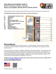
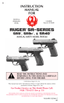
1
Owner Manual and Installation Guide for
NRA® Home Defense Cabinet by Jotto Gear
Models: 430-0100, 430-0101, 430-0111, 430-0112
Using the diagram and key on this page, please familiarize yourself with this product and the components listed.
Each NRA® Home Defense Cabinet by Jotto Gear comes with: (See Figure A.)
(1)
(2)
(3)
(4)
(5)
(6)
(7)
(8)
(9)
(10)
(11)
(12)
(13)
Top Slide Bracket Assembly w/Latch
Cabinet Shelf
Master Biometric Control Unit
Wall Insert
Frame
Biometric Handgun Holster
(Included in Models 430-0101 & 430-0112)
Mirror
Lock Head Assembly
Trigger Guard
Butt Rest
Butt Rest Bracket
Bottom Slide Bracket
Installation Hardware Bag (not shown)
90 Day Limited Warranty
This warranty is extended solely to the original purchaser.
A purchase receipt or other proof of date of original
purchase and a Jotto Gear RGA# will be required for
returned items. All defective parts for replacement must be
returned to factory.
This warranty does not cover labor for installation or
damages to home during installation. This warranty only
covers failures due to defects in materials or workmanship
which would occur during normal use. This warranty does
not cover any frames modified or finished by consumer, or
parts failures which result from alteration, accident,
misuse, abuse, damages during theft, improper
installation, modification or service by anyone other than
Jotto Gear. This warranty does not cover damage that is
attributable to acts of God.
Figure A.
Should you find a part missing or damaged please
contact Jotto Gear Customer service at 1-800-979-3375
or by chat at www.NRAJOTTOGEAR.com
Keep this Owners Manual as reference.
NRA HDC II – Rev. 00 2.11.14
Page 1
Owner Manual and Installation Guide for
NRA® Home Defense Cabinet by Jotto Gear
Models: 430-0100, 430-0101, 430-0111, 430-0112
Table of Contents
Jotto Gear Contact Information ……………………………………………………………………
Parts Diagram …………………………………………………………………………………………
90 Day Warranty ………………………………………………………………………………………
Table of Contents ……………………………………………………………………………………..
Important Warnings …………………………………………………………………………………..
Tools Required for Installation ……………………………………………………………………..
Opening, Removing, Attaching Frame ……………………………………………………………
D.I.Y. Finishing Frame ……………………………………………………………………………….
Frame Sliding Options ……………………………………………………………………………….
Determining Location for Install ……………………………………………………………………
Weapon Mount Adjustments …………………………………………………………………........
AR Option Lock Head Adjustment ………………………………………………….......
Shotgun Option Lock Head Adjustment ………………………………………………..
Optional Handgun Adjustment …………………………………………………………...
Pre-Drilling ……………………………………………………………………………………………..
Mirror Attachment …………………………………………………………………………………….
Mounting Defense Cabinet ………………………………………………………………………….
Troubleshooting Programming Tips ………………………………………………………………
Biometrics Programming ……………………………………………………………………….......
Biometrics Operation ………………………………………………………………………………...
Firearm Fit Chart ………………………………………………………………………………………
Page 1
Page 1
Page 1
Page 2
Page 3
Page 3
Page 4
Page 4
Page 5
Page 6-7
Page 7
Page 8
Page 9
Page 10-11
Page 11
Page 12
Page 12-15
Page 16
Page 16-19
Page 19
Page 20
Models: (*See Fit Chart)
430-0100 – Single Firearm Model – Medium Finished Frame – Shotgun or AR*
430-0101 – Dual Firearm Model – Medium Finished Frame – Shotgun or AR and one Handgun*
430-0111 – Single Firearm Model – D.I.Y. Unfinished Frame – Shotgun or AR*
430-0112 – Dual Firearm Model – D.I.Y. Unfinished Frame – Shotgun or AR and one Handgun*
Key Features
The master biometric control unit offers an entry
switch option for Smart Home systems and/or home
security alarm systems. This feature works similarly
to wired entry sensors of many alarms. Sensor
access hook-up connector is located on the back of
unit and is not compatible with wireless sensor type
systems. When wired correctly, if user scans the
lock heads to open, it will also signal home alarm
control system. The wiring should be installed prior
to mounting wall insert, for use of this option.
Consult with your alarm system provider on wiring,
programming setup or entry sensor compatibility.
Biometrics control unit also features downward red
cabinet light that briefly illuminates firearms while
accessing.
Biometrics control unit can store up to 99 separate
finger prints for entry.
NRA HDC II – Rev. 00 2.11.14
Page 2
Owner Manual and Installation Guide for
NRA® Home Defense Cabinet by Jotto Gear
Models: 430-0100, 430-0101, 430-0111, 430-0112
FAILURE TO FOLLOW THESE WARNINGS MAY RESULT IN SERIOUS INJURY
OR DEATH TO YOU OR OTHERS
WARNING:
WARNING:
WARNING:
WARNING:
WARNING:
WARNING:
WARNING:
WARNING:
WARNING:
WARNING:
WARNING:
READ MANUAL AND INSTALLATION GUIDE BEFORE USING
This storage device is not a substitute for a gun safe. Given sufficient time any
firearm storage device may be compromised.
Neither the NRA® Home Defense Cabinet by Jotto Gear nor any other firearm
device can take the place of other safety procedures including advising children of the
dangers of firearms and keeping firearms away from the untrained.
Empty firearms of all ammunition before storing. Do not store with rounds in firearms.
Store magazines and ammunition separately.
Always keep fingers clear of trigger when removing or replacing firearms.
Keep thumb on back of hammer or slide when inserting pistol in holster to
insure pistol is not cocked during insertion.
Always store firearms in the NRA® Home Defense Cabinet with safety in closed
and locked position.
Use only with firearms listed in user’s manual. Do not use firearms not listed.
Always handle firearms as if they are loaded and ready to fire.
Never mix alcohol or drugs with firearms, the NRA® Handgun Holster or
NRA® Home Defense Cabinet.
Always follow firearm safety rules set out by the firearm’s manufacturer.
Tools needed for Installation
1)
2)
3)
4)
5)
6)
7)
Stud finder
Sheet rock saw or utility knife
Tape measure
Philips screw driver #1 tip
Level
Drill
Masking Tape
NRA HDC II – Rev. 00 2.11.14
7)
8)
9)
10)
11)
3/16” drill bit
1/2" drill bit
7/16” socket and driver or drill attachment
3/16” Allen wrench
Un-loaded firearm intended for use with HD cabinet
Reference last page for firearm compatibility
12) 6 x “AA” Lithium Ion batteries only
Page 3
Owner Manual and Installation Guide for
NRA® Home Defense Cabinet by Jotto Gear
Models: 430-0100, 430-0101, 430-0111, 430-0112
Upon receiving your NRA® Home Defense Cabinet, remove all
packaging materials and the items within wall insert and frame
assembly.
Leave protective film on finished frame during installation and mirror
assembly instruction steps, to prevent scratches.
The cabinet comes factory assembled with wall insert, frame and
biometrics control unit all attached. The frame will slide open to left
hand side of cabinet. When installed, this will require 22 inches of
clear space left of frame.
If frame comes pre-finished and desired location has adequate
space for sliding frame you can skip to page 6, Step 1.
Depending on chosen location for cabinet, the direction of sliding
frame may not work. Rotation of sliding rails may be necessary to
open cabinet frame fully. To change cabinet opening direction,
follow “Removing Frame Instructions” and “Optional Right Hand
Instruction”. The optional right hand sliding will require 22 inches of
clear space right of frame instead.
Locate latch in top right corner of wall insert assembly and press up
slightly to open frame.
REMOVING FRAME INSTRUCTIONS
After opening frame, place frame face down on soft surface to
prevent damage to frame.
Locate black detach levers on back of top and bottom sliding rails
mounted to frame. Press and hold detach levers while sliding rails
and rest of wall insert off of frame.
During re-assembly keep magnets mounted on inside of frame
towards top side of wall insert. These magnets swipe across
biometrics control unit in cabinet and awaken unit for use.
D.I.Y. unfinished frames should be finished as desired prior to
completing any other steps. Please allow for adequate curing
time for any finishes prior to continuing further assembly.
Important Note: Frame is not returnable or covered by any
warranty once consumer modifies or applies any finishes such
as stains, primers, paints or other coatings.
NRA HDC II – Rev. 00 2.11.14
Page 4
Owner Manual and Installation Guide for
NRA® Home Defense Cabinet by Jotto Gear
Models: 430-0100, 430-0101, 430-0111, 430-0112
RIGHT HAND SLIDING INSTRUCTIONS
Top and bottom slide brackets should remain riveted to plastic wall
insert throughout installation.
After sliding frame off wall insert assembly, unscrew slide rails from
brackets of wall insert and from frame.
Rotate all slide rails 180 degrees.
Align screws with new circled hardware positions in picture below.
Secure rails with same screws previously removed.
Assure rails are parallel with frame edge. Properly installed rails
make re-attachment of sliding frame easier.
Once rotated and screws re-secured, the finished frame can be
assembled by aligning mating slides of wall insert and sliding back
together.
NRA HDC II – Rev. 00 2.11.14
Page 5
Owner Manual and Installation Guide for
NRA® Home Defense Cabinet by Jotto Gear
Models: 430-0100, 430-0101, 430-0111, 430-0112
Before you begin, make sure the location
you choose is free of all electrical,
plumbing and mechanical services.
In cases where electrical or plumbing
needs relocation, consult with a licensed
professional contractor for these services.
Also be careful installing behind opening
doors. Door knobs may damage frame or
break mirror when door is opened fully.
STEP 1:
Determining the
Installation Location
When installed, the height of the mirror will be determined by the cut out. Consider the height prior to cutting any
holes, as it may impact practical use of mirror and cabinet for all purposes. Also, consider 22 inches of clearance is
needed next to cut out for the sliding frame to open properly.
Dimensions of cut out are:
14.5” width
56.25” length
The NRA® Home Defense Cabinet is designed to fit into an interior standard stud wall built with 2x4’s on 16” centers.
Once you have located where you want to install your NRA® Home Defense Cabinet, you will need to cut out a hole
large enough to fit the wall insert. Use a stud finder to locate the studs that will be on the left and right sides of the
wall insert.
NRA HDC II – Rev. 00 2.11.14
Page 6
Owner Manual and Installation Guide for
NRA® Home Defense Cabinet by Jotto Gear
Models: 430-0100, 430-0101, 430-0111, 430-0112
STEP 1:
Determining the
Installation Location
(Continued)
Once you have determined your left and right stud locations, using a pencil, draw a horizontal line between the studs
at the bottom end of where you want your wall insert to begin. Measure up 56.25” and draw another horizontal line
between the left and right studs. Before you cut out the drywall, put the wall insert up against the wall and ensure that
the hole you have measured will fit the wall insert, and the frame is at the desired usable height.
An interior wall properly framed on 16” centers will leave a standard of 14.5” inside distance between studs. Use a
drywall saw or utility knife to cut out the drywall. Make a small cut all the way through the drywall just to the inside of
where the left or right stud is. Cut towards the stud to locate the inside edge of the stud. Cut out drywall in between
studs, cutting along studs to the top and bottom lines and across lines drawn in previous step. Place cabinet wall
insert assembly into wall, resting it on the bottom edge of the drywall opening. The cabinet wall insert is designed to
fit between a standard stud built internal wall. If you can slide the insert more than a 1/4“ sideways, you will need to
shim out one side as needed for a secure fit. Studs located too close together, may need trimmed to fit insert.
Read following warnings before
attempting Step 2 through Step 6.
Failure to follow this warning may
result in serious injury or death.
Empty any firearms of all ammunition
before using for installation purposes.
Failure to follow this warning may
result in serious injury or death.
Failure to follow this warning may
result in serious injury or death.
Proper mounting of components
required to properly secure firearms.
Lock head and butt rest placement
should be placed so that the firearm
cannot be removed while firearms are
in stored position and cabinet is in
locked mode.
Emergency Override Key: Opens the
Lock Head.
Removing key will not lock the lock
head. You must lock the lock head
electronically.
NRA HDC II – Rev. 00 2.11.14
Page 7
Owner Manual and Installation Guide for
NRA® Home Defense Cabinet by Jotto Gear
Models: 430-0100, 430-0101, 430-0111, 430-0112
STEP 2: Adjustment for Firearms
.
Mocking up placement of firearms will need to be done
inside the wall insert. Wall insert can be left vertical in wall
cut out or can be removed from cut out and laid on flat
surface for this pre-assembly.
Loosely attach butt rest to butt rest bracket with two 1/4-20
flat head screws and two 1/4-20 flange nuts. This will allow
sliding adjustment to be made in later step.
Place butt rest assembly into wall insert and hand tighten two 1/4-20 hex
head bolts with washers.
The rounded end of the butt rest should face the right side of the wall
insert that the lock head will be mounted to.
Continue with current page for AR rifle setup or page 9 for shotgun setup
instructions.
AR Option Instruction
Due to different firearm sizes, lock head positioning will need
to be determined before mounting.
Place unloaded firearm intended for use with cabinet into
butt rest attached in previous step and wall insert frame
assembly.
Unlock lock head with Override Key, open and place barrel
of gun inside lock head, then close.
Place strips of masking tape vertically on inside wall insert to
mark on for mounting hole placement of lock head.
The face of lock bracket should fit flush inside wall insert not
to obstruct sliding of frame.
Mark both holes for mounting lock head and one spot
directly behind lock head for cable access.
Adjust butt rest by sliding so that barrel is parallel to wall
insert for best fit.
Use Phillips screw driver and 7/16” wrench to tighten butt
rest to butt rest plate.
NRA HDC II – Rev. 00 2.11.14
Page 8
Owner Manual and Installation Guide for
NRA® Home Defense Cabinet by Jotto Gear
Models: 430-0100, 430-0101, 430-0111, 430-0112
Shotgun Option Instruction
Due to different firearm sizes, lock head positioning will need to be
determined prior to mounting.
Open lock head with provided Override Key to access the two Allen
head screws.
Remove Allen screws to remove AR bracket. Replace lock head by resecuring screws. 3/16” Allen screw driver required.
Open and place receiver of shotgun inside lock head, then close.
If receiver of shotgun does not fit, use AR Option Instruction on page 8.
Depending on barrel type of firearm, the AR barrel bracket may be
required.
Place strips of masking tape vertically on inside of wall
insert to mark on for mounting hole placement of lock
head.
The face of lock bracket should fit flush inside wall insert
not to obstruct sliding of frame.
Mark both holes for mounting lock head and one spot
directly behind lock for cable access to lock head.
Adjust butt rest by sliding so that barrel is parallel to wall
insert for best fit.
Use Phillips screw driver and 7/16” wrench to tighten butt
rest to butt rest plate.
NRA HDC II – Rev. 00 2.11.14
Page 9
Owner Manual and Installation Guide for
NRA® Home Defense Cabinet by Jotto Gear
Models: 430-0100, 430-0101, 430-0111, 430-0112
Handgun Holster Option Setup
(Models: 430-0101 and 430-0112 only)
The handgun holster will only lock and unlock with
biometric control unit active and programmed.
Upon receiving holster, a removable tab will keep
weapon unlocked while adjusting. Only remove tab after
adjusting barrel stop to correct position.
Supplied with the handgun holster is a security torx bit to
be used with universal drivers or to be installed in
electronic screw drivers.
Lift bale of handgun holster to insert unloaded firearm.
Insert firearm into holster and close bale behind firearm,
adjustment to barrel stop may be needed.
Adjust the single security screw on the top front of
holster.
Final adjustment should not bind action of bale on
handgun holster when secured. If firearm is too
tight it may prevent lock from opening during normal
operation.
Larger handguns may require removal of barrel stop
and/or shim under the trigger guard to fit properly.
Once comfortable with fit, remove handgun until later steps when cable is installed.
Removable tab can removed at this time and bale may lock until electronically opened again.
The security torx bit to adjust barrel stop will be used for securing bracket in later steps and keep in safe
place for future adjustment if firearm change is needed.
NRA HDC II – Rev. 00 2.11.14
Page 10
Owner Manual and Installation Guide for
NRA® Home Defense Cabinet by Jotto Gear
Models: 430-0100, 430-0101, 430-0111, 430-0112
Handgun Holster Option
(Models: 430-0101 and 430-0112 only)
Selected models may come with the Handgun Holster
option. This step should be completed before mounting
wall insert frame assembly into wall.
Careful not to mount handgun holster too low, leave
enough room for the rifle to be removed without
interference with the handgun holster and handgun grip.
Place vertical strips of masking tape into wall insert to
mark two holes for handgun bracket mounting hardware.
Also mark a spot on the back of wall insert for biometric
cabling.
Bracket should be placed into wall insert to allow room for
handgun holster, align holes of bracket 1.5 inches from
front edge of black wall insert.
STEP 3: Pre-Drilling
.
If wall insert is located in wall cut out remove for pre-drilling.
Use 3/16” drill bit to drill pilot holes for all mounting hardware of
lock head, cable access points and handgun holster cable with
selected handgun holster mount option.
Use 1/2” drill bit to make cable access points large enough to get
cable connector through holes.
Remove masking tape for holes.
Pull several inches of cable from biometric control unit through
each access hole and tape down.
Tape all excess cable(s) to back of wall insert to prevent damage
or pinching during mounting.
NRA HDC II – Rev. 00 2.11.14
Page 11
Owner Manual and Installation Guide for
NRA® Home Defense Cabinet by Jotto Gear
Models: 430-0100, 430-0101, 430-0111, 430-0112
STEP 4: Mirror Installation
.
Prior to mounting the wall insert into the cut out, place frame assembly face down on soft surface to install mirror.
Slide frame wall insert assembly to open position exposing back of frame. Carefully place mirror into frame.
Attach mirror by securing with six #8 x .5” screws and provided mirror retaining tabs found in installation hardware
bag. Finished mirror assembly should have three mirror retaining tabs on each of the two vertical sides.
STEP 5: Mounting Wall Insert Assembly
.
Check all cable(s) to ensure they are attached to
back of biometric control unit.
If using with security alarm, final wiring can be run
through hole by biometric control unit when inserted
into wall cut out.
The biometric control unit comes attached by two
Phillips screws, for better access to rear connectors.
All weapon mount cable connectors should clip in
and may require a small flat head screw driver to
release clip for removal.
NRA HDC II – Rev. 00 2.11.14
Page 12
Owner Manual and Installation Guide for
NRA® Home Defense Cabinet by Jotto Gear
Models: 430-0100, 430-0101, 430-0111, 430-0112
STEP 5: Mounting Wall Insert Assembly
(continued)
Place frame with mirror and wall insert assembly back into
wall cut out.
Slide mirror and frame fully open.
Wall insert and slide brackets should fit flush and level with
wall before securing any hardware.
Set hand level on top rail when securing mounting hardware.
This will ensure frame remains level while in closed position.
Use two provided lag bolts and washers in the slotted hole of
each corner bracket. Align with pre-drilled pilot holes.
Remove butt rest assembly to access slots for bottom lag
bolts.
Once all corners are secure, slide frame open and closed to
check fit. Adjustments can be made by loosening lags bolts,
adjusting and retighten.
Press all eight black bolt head caps on after securing bolts.
Place butt rest bracket assembly back onto the bottom slide
bracket.
Re-secure hardware on butt rest plate with 7/16” wrench to
bottom slide bracket.
Attach biometric cable through bottom of lock head assembly.
This biometric cable should lock into place, use a flat head screw driver to
lightly push into place if needed.
Caution: Excessive force on cable, should not be used.
Have 7/16” socket driver close by and ready to secure bracket to wall
insert and 2x4 stud inside wall.
NRA HDC II – Rev. 00 2.11.14
Page 13
Owner Manual and Installation Guide for
NRA® Home Defense Cabinet by Jotto Gear
Models: 430-0100, 430-0101, 430-0111, 430-0112
Secure two lag bolts and washers through the pre-drilled holes in
wall insert with 7/16” wrench.
The face of the lock head bracket should be flush with wall
insert.
Tuck excess cabling back into hole to keep out of the way.
Slide frame across to verify lock head does not interfere.
Press two black caps onto heads of secured lag bolts.
Open lock and check fit of firearm.
RISK OF SERIOUS INJURY OR DEATH
Trigger guard should be mounted in a
position that deters inadvertent trigger
activation.
Installing Trigger Guard
Determine trigger guard placement by positioning over
trigger and receiver action of firearm.
Place vertical strips of masking tape between trigger guard
slots and wall insert on to wall insert.
Remove firearm and mark center of slots for mounting
hardware.
Drill 3/16” pilot holes in center of marked slots and secure
trigger guard to wall insert with two 7/16” lag bolts and
washers.
Careful not to interfere with sliding frame, trigger guard
should be mounted flush with wall insert while securing.
The firearm also should be placed back into the cabinet to
re-check fit.
Final adjustments should be made before pressing two
black bolt head caps to finish.
NRA HDC II – Rev. 00 2.11.14
Page 14
Owner Manual and Installation Guide for
NRA® Home Defense Cabinet by Jotto Gear
Models: 430-0100, 430-0101, 430-0111, 430-0112
STEP 6: Mounting Handgun Holster
(Step only necessary with select models)
.
Secure handgun holster mounting bracket with two 7/16” lag bolts and
washers.
Press two black caps on heads of mounting holes.
Attach second biometric cable to handgun holster.
Use the provided security torx bit in a universal driver.
Secure base of handgun holster to bracket with two provided
10-32 security screws.
Save security torx bit and instructions for future use.
Excess wire can be tucked back into hole to prevent interference
with firearm.
Slide frame open and closed to check clearance of all mounts and
firearms.
Attach Shelf
Remove backing from hook and loop strips on upper bracket
and set plastic shelf in place.
Shelf is removable to access screws on top of biometrics
control unit.
NRA HDC II – Rev. 00 2.11.14
Page 15
Owner Manual and Installation Guide for
NRA® Home Defense Cabinet by Jotto Gear
Models: 430-0100, 430-0101, 430-0111, 430-0112
STEP 7: Programming Biometrics
.
Orange LED – Program Setup Mode (Master User only)
Red LED – Primary Awaken Mode
Green LED – Scanning Mode
White button – Program Button and Wake Up Button
When determining a Master User program finger, select a finger that has the best
definition and fingerprint ridges to be a master program finger. Other fingers can be
programmed later. Light, smooth or finger prints lacking good definition may be
more difficult read and not recommended for Master User program finger. A thumb
may work better due to size of finger and surface to read.
Biometric Control Unit can ONLY be reset back to factory settings by Master
User finger or sent back to Jotto Gear. Circle chosen master program finger
on manual and keep safe for future reference. Forgetting which finger is the
Master User will prevent ability to program new users or erasing users in
future.
Troubleshooting Programming Tips:
An ORANGE LED means the biometrics reader is prompting for the Master User scan.
During initial setup, if biometrics remains ORANGE after programming. The scanner did not get a good read during
one or more attempts. Start over from the beginning of Master User setup.
At the end of programming any sequences, if biometric control unit beeps and flashes RED LED’s and ORANGE
LED’s multiple times the user may need to start over.
If the biometric unit will not open locks by Master User during a programming attempt, resetting batteries may be
necessary.
Inserting Batteries
Remove all four top screws on biometrics control unit.
Insert six “AA” Lithium Ion Batteries Only.
Once batteries are inserted, a Master User fingerprint will need to be
present to program for first time. Biometric control unit will continue
to cycle power and beep until Master is programmed.
Attach top of control unit to base with four previously removed
screws.
Low Battery Warning
The biometric reader will intermittently check if batteries are low. An alert signal will sound with four beeps every 15
minutes, until batteries are replaced. Only “AA” Lithium Ion batteries should be used.
Recommended battery replacement is every 6 months.
NRA HDC II – Rev. 00 2.11.14
Page 16
Owner Manual and Installation Guide for
NRA® Home Defense Cabinet by Jotto Gear
Models: 430-0100, 430-0101, 430-0111, 430-0112
Before Starting: Be sure to read and understand each step prior to attempting.
Waiting too long in between steps will cause the scanner to time out.
Align crease below finger print on dot of scanner for
best results.
For extra help with programming setup, use QR
Codes or URL address for online video instructions.
Out-of-the-Box Setup Instructions for Master User
Note: After inserting batteries the scanner will cycle power every 30 to 40 seconds. Start Step 1 within 5 seconds or
wait until next power cycle for best results.
http://scan.me/hpjmxz
Step 1)
At ORANGE LED prompt, scan your selected Master User finger by pressing firmly and holding finger still for three
continuous beeps. Remove finger after third beep.
Step 2)
Wait for fourth beep without scanning finger.
Step 3)
Wait for scanner to cycle power and come up to RED LED prompt. If ORANGE LED prompt reappears, start Out-ofthe-Box programming over.
Step 4)
During RED LED prompt, scan Master User finger to open lock(s) and verify setup.
Note: Adjust finger slightly, if lock(s) do not open within 1 to 2 seconds.
Note: If scanner sounds multiple beeps after third Master finger scan, one of finger scans had a bad read.
To ensure best performance, follow steps on page 19 to “Erase All Users Instructions” and repeat “Out-of-the-Box
Setup”.
NRA HDC II – Rev. 00 2.11.14
Page 17
Owner Manual and Installation Guide for
NRA® Home Defense Cabinet by Jotto Gear
Models: 430-0100, 430-0101, 430-0111, 430-0112
Before Starting: Be sure to read and understand each step prior to attempting.
Waiting too long in between steps will cause the scanner to time out.
To Program New Users or Additional Fingers
Only Master User finger will be able to program additional fingers/users.
Step1) - Master User step
Slide the mirror past biometrics reader or press white program button.
http://scan.me/6c3src
Step 2) - Master User step
Scan Master User finger to unlock firearms. Press white program button and wait 15 seconds for ORANGE LED
prompt to scan Master User finger a second time. Remove Master User finger quickly as GREEN LED prompts for
New User finger.
Step 3) – New User step
During GREEN LED prompt, scan New User finger by pressing firmly and holding new finger still for three continuous
beeps. Remove finger after third beep.
Step 4) – New User step
Wait for scanner to cycle power and come up to RED LED.
Step 5) – New User step
During RED LED prompt, scan new finger to open lock(s) and verify setup.
Note: Adjust finger slightly if lock(s) do not open within 1 to 2 seconds.
Note: If scanner has multiple beeps after third New User finger scan, one of the finger scans had a bad read.
To ensure best performance repeat New User Programming steps over.
Do not erase, unless reprogramming all users including Master User.
NRA HDC II – Rev. 00 2.11.14
Page 18
Owner Manual and Installation Guide for
NRA® Home Defense Cabinet by Jotto Gear
Models: 430-0100, 430-0101, 430-0111, 430-0112
Before Starting: Be sure to read and understand each step prior to attempting.
Waiting too long in between steps will cause the scanner to time out.
Erasing All Users Instruction
Performing this operation will erase all users including Master User and set unit back to factory default.
Only Master User finger will be able to perform these steps.
Step1) - Master User step
Slide the mirror past biometrics reader or press white program button.
Step 2) - Master User step
Scan Master User finger to unlock firearms. Press white program button and wait 15 seconds for ORANGE LED.
Step 3) - Master User step
During ORANGE LED, press and hold white button and hold Master User finger in place on the scanner
simultaneously.
Note: While holding finger and button in place, ORANGE LED will alternate to GREEN LED four times followed by
two series of six beeps and flashing GREEN LEDs.
During second series of beeps, remove hands from biometrics control unit and wait for unit to reset.
Step 4) - Master User step
Biometrics will reset back to factory default. ORANGE LED will display, user should return to Page 17 for “Out-of-theBox Instruction” on programming a new Master User.
If not scanning new Master User right away, remove batteries to turn off biometric control unit.
General Operation
Once programmed, sliding frame open will awaken biometric control unit for
approximately 20 seconds.
After 20 seconds, the biometric control unit will go back to sleep. Press the
white button or close and re-open the framed mirror to awaken.
Scan a programmed finger to unlock for firearm retrieval. The lock should
remain open for approximately 8 seconds before auto-locking.
The cabinet will light during unlocking period.
This light will remain on for approximately 15 seconds before turning off.
NRA HDC II – Rev. 00 2.11.14
Page 19
Owner Manual and Installation Guide for
NRA® Home Defense Cabinet by Jotto Gear
Models: 430-0100, 430-0101, 430-0111, 430-0112
Firearm Fit Chart
ALL NRA HOME DEFENSE CABINETS MODELS
MODELS 430-0101 & 430-0112 ONLY
SHOTGUN MODELS
CZ-USA - CZ612
Mossberg - 590SP, 500
Remington - 870, 870 Tactical, 870 Express
Winchester - SXP Defender, SXP Extreme Defender
HANDGUN MODELS
Beretta - 84, 92, 96, M9, PX4 Storm, Nano
Bersa - Thunder 380
Colt - Defender, 1911, 1991, XSE, Rail Gun, New Agent,
Series 70, Combat, Delta
CZ - CZ 75
EAA - Witness
FNH - FNX, FNS, Five-Seven
Glock - 17, 19, 21, 22, 23, 26, 27, 30, 33, 34, 35, 36, 37
HK - P30, USP, USP Compact, HK45, HK45 Compact
Kel Tech - PF9
Kimber - 1911, 1911 Compact
Khar - K9
Lionheart - L9C
Remington - 1911 R1
Ruger - SR9, SR9C, SR1911
Sig Sauer - P220, P226, P228, P229, P245, P250,
Mosquito, SP2022
Smith & Wesson - 5906, 6946, M&P 9, M&P 40, M&P 45,
M&P Shield
Springfield - XD, XDm, XDs, 1911 Range Officer, Trophy
Match, TRP, Operator, EMP, Ultra
Steyr - M9 A1
Taurus -709 Slim, PT809, PT840, PT845, PT24/7, 1911,
PT92, PT100, PT101, Millennium
Tanfoglio - TZ75
Walther - PK380, PPS, P99, PPX, PPQ
Wilson Combat - 1911
AR-AK STYLE RIFLE MODELS
ArmaLite
Barrett Firearms Manufacturing
Bushmaster Firearms International
Colt's Manufacturing Company
DPMS Panther Arms
High Standard Manufacturing Company
Knight's Armament Company
Land Warfare Resources Corp Intl (LWRCI)
Magpul Industries
Olympic Arms
Para-Ordnance (Para-USA)
Remington Arms
Rock River Arms
Ruger
Sabre Defence/Manroy USA
Sig Sauer
Smith & Wesson
Stag Arms
NRA HDC II – Rev. 00 2.11.14
Page 20