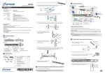
Download User Manual
Transcript
EMR Series
Professional/Enterprise
Megapixel Video Recorder
User Manual
Release 1.1
About This Document
This manual introduces EMR series systems and the procedures on how to install,
monitor, and maintain them.
Version History
Version
Description
Date
1.0
Initial release: All the EMR series models
April 2012
are put into this manual; both hardware
and software aspects are covered.
1.1
Revise the default RAID level for EMR5000
June 2012
series to non-RAID only.
2
All Rights Reserved © Surveon Technology 2012
Copyright Statement
No part of this publication may be reproduced, transmitted, transcribed,
stored in a retrieval system, or translated into any language or computer
language, in any form or by any means, electronic, mechanical, magnetic,
optical, chemical, manual or otherwise, without the prior written consent of
Surveon Technology Inc.
Disclaimer
Surveon Technology makes no representations or warranties with respect to
the contents hereof and specifically disclaim any implied warranties of
merchantability or fitness for any particular purpose. Furthermore, Surveon
Technology reserves the right to revise this publication and to make changes
from time to time in the content hereof without obligation to notify any
person of such revisions or changes. Product specifications are also subject to
change without notice.
Trademarks
Surveon and Surveon logo are trademarks of Surveon Technology Inc. Other
names prefixed with “SMR” and “EMR” are trademarks of Surveon Technology
Inc.
Microsoft Windows and Windows are registered trademarks of Microsoft
Corporation.
Linux is a trademark of Linux Torvalds.
Solaris and Java are trademarks of Sun Microsystems, Inc.
All other names, brands, products or services are trademarks or registered
trademarks of their respective owners.
3
Table of Contents
About This Document .................................................................... 2
Version History ........................................................................... 2
Copyright Statement .........................................................................3
Table of Contents .............................................................................4
Safety Precautions ............................................................................6
Device Site Recommendations..............................................................6
Chapter 1. Product Overview...............................................................7
1.1. Features and Benefits ...............................................................7
EMR2000/5000 Series .................................................................... 7
EMR8000 Series ........................................................................... 7
EMR9000 Series ........................................................................... 7
1.2. Specifications for the EMR Series .................................................8
Model List for EMR Series ............................................................... 8
Hardware Specifications ................................................................ 8
Chapter 2. Hardware Overview ............................................................9
2.1. Front Panel ............................................................................9
2.2. Rear Panel ........................................................................... 10
2.3. Hard Drive Designation............................................................ 11
2.4. LED Definitions ..................................................................... 12
Desktop System LED Front Panel..................................................... 12
Rackmount System LED Front Panel ................................................. 13
Drive Tray LED .......................................................................... 14
Rear Panel Ethernet LED .............................................................. 15
Chapter 3. Installation ..................................................................... 16
3.1. Installation Flow Chart ............................................................ 16
3.2. Rackmounting....................................................................... 17
Installing Enclosure Slide Rails ....................................................... 18
Rack-Mounting EonStor DS RAID Subsystem(s) (Optional) ........................ 20
3.3. Adding Hard Drives (Optional) ................................................... 21
4
Hard Drive Installation Prerequisites ................................................ 21
Inserting Hard Drive into Drive Tray................................................. 21
3.4. Cabling ............................................................................... 24
Desktop System Connection Concept................................................ 24
Rackmount System Connection Concept............................................ 25
3.5. Powering up EMR ................................................................... 26
Desktop System......................................................................... 26
Rackmount System ..................................................................... 27
Checklist................................................................................. 27
Rackmount System LED Front Panel Status......................................... 29
Chapter 4. Software Installation ......................................................... 30
4.1. Milestone Installation.............................................................. 30
Milestone XProtect Level.............................................................. 30
Installing Milestone XProtect Server on the EMR System ......................... 30
Basic System Settings through Wizards ............................................. 31
Installing Milestone XProtect Smart Client on Remote PC(s) .................... 32
Starting Milestone XProtect Smart Client........................................... 32
4.2. RAID Configurations for Additional Hard Drives (Optional)................. 34
RAID Configurations through Intel Utility ........................................... 35
RAID Configurations through HighPoint Utility ..................................... 37
4.3. RAID Configurations for Eonstor DS RAID Subsystem(s) (Optional)........ 40
System Event Notifications ...................................................... 42
4.4. Extending Trial Licenses for Milestone XProtect ............................ 44
Precondition ....................................................................... 44
Activating a License .............................................................. 44
Precondition ....................................................................... 45
Chapter 5. System Maintenance ......................................................... 48
5.1. Replacing the Power Supply Module (for Rackmount Series) .............. 48
5.2. Replacing the Slot Fan Module (for Rackmount Series) ..................... 51
5.3. Replacing a Hard drive (for Desktop Series) .................................. 53
5.4. Replacing a Hard drive (for Rackmount Series) .............................. 55
5
Safety Precautions
Electric Shock Warning
This equipment may cause electric shocks if not handled properly.
Access to this equipment should only be granted to trained operators
and maintenance personnel who have been instructed of, and fully
understand the possible hazardous conditions and the consequences of
accessing non-field-serviceable units such as the power supplies.
The system must be unplugged before moving, or in the even that it
becomes damaged.
Reliable Grounding
Particular attention should be given to prepare reliable grounding for the
power supply connection. It is suggested to use a direct connection to the
branch circuit. Check for proper grounding before powering on the device.
Overloading Protection
The device should be installed according to specifications. Provide a suitable
power source with electrical overload protection. Do not overload the AC
supply branch circuit that provides power to the device.
ESD Precautions
Please observe all conventional anti-ESD methods while handling the device.
The use of a grounded wrist strap and an anti-static work pad are
recommended. Avoid dust and debris in your work area.
Device Site Recommendations
The device should be installed according to specifications. This device should
be operated at a site that is:
Clean, dry, and free of excessive airborne particles.
Well-ventilated and away from heat sources such as direct sunlight
and radiators.
Clear of vibration or physical shock.
Away from strong electromagnetic fields produced by other devices.
Available with properly grounded wall outlet for power. In regions
where power sources are unstable, apply surge suppression.
Available with sufficient space behind the device for cabling.
6
Chapter 1. Product Overview
1.1. Features and Benefits
Megapixel solutions are the key trend in video surveillance with the advanced
benefit of 6-time better image clarity. However, high I/O, huge capacity, and
stability of the overall system are major challenges for system integrators. The
Professional/Enterprise Megapixel Video Recorders, allied with the most
qualified partners in the industry, provide a high performance and reliable
platform.
EMR2000/5000 Series
The EMR2000/5000 series secures the multi-channel megapixel recording
performance. The industrial grade design of 2/5 HDDs, 2 GLAN have made
EMR2000/5000 series absolute choices over the commercial PCs and the ideal
solution for small retail, gas station, residential and small business field
application.
EMR8000 Series
Built-in with the HW RAID, the EMR8000 secures the multi-channel megapixel
recording performance. The industrial grade design of 8 HDDs, dual display, and
2 GLAN have made EMR8000 series an absolute choice over the commercial PCs
and the ideal solution for mission critical projects, such as hotel, school, bank
and factory.
EMR9000 Series
Built-in with the world's leading EonStor HW RAID subsystem, the EMR9000 series
secures the multi-channel megapixel recording performance while keeping the
scalability for the maximum of 112 disks. The industrial grade design of XEON
Quad Core processor, 2 SAS ports, 6 GLAN and redundant module have made
EMR9000 series an absolute choice over the commercial PCs and the ideal
solution for mission critical surveillance projects, such as hotel, school, bank,
factory, transportation, city surveillance and public utility.
7
1.2. Specifications for the EMR Series
Model List for EMR Series
EMR2000 Series
EMR5000 Series
EMR8000 Series
Professional Megapixel HW RAID NVR
EMR9000 Series
Enterprise Megapixel HW
RAID NVR
Hardware Specifications
EMR2000 Series
EMR5000 Series
EMR8000 Series
EMR9000 Series
System Processor
Intel ®Dual Core @ 1.8 GHz
Intel ® Core i3 – 2100
Intel® XEON Quad Core
System Memory
DDR3 2GB
DDR3 4GB
DDR3 4GB (24GB Max.)
Chipset
Intel
®
ICH9R
®
Intel
Q67
Express
Chipset
Storage
3.5” SATA HDD ; HDD hot swappable
Hard Disk Trays
2 bay
I/O Interface
5 bay
1x D-Sub
2x1 GbE
5x USB2.0
1x e-SATA
8 bay
2 bay
1x D-Sub/1x HDMI
2x1 GbE
7x USB2.0
1x COM
Electrical
Operating
Environment
Input Voltage:
12VDC, 5A
Power Consumption
(in operation): 43W
Input Voltage:
100~240VAC, 3.5A
Frequency:
47~63Hz
Power
Consumption
(in operation): 43W
Humidity: 5 to 80% (non-condensing)
Temperature: 5 to 40°C
No
Yes
LED Indicator
Dimensions (mm)
Yes
190(H) x 110(W) x
245(D)
3 kg
225(H) x 175(W) x 245(D)
8
LCD Panel
Weight
(without hard
drives)
Certificate
Input Voltage:
100~240VAC, 4~8A
Frequency: 47~63Hz
Power Consumption (in
operation): 430W
5 kg
1x DVI/1x HDMI
2x 1 GbE
4x 1Gb iSCSI
2x 6Gb SAS
2x USB2.0
1x COM
Input Voltage: 115 VAC @
6A/240 VAC @ 3 A
Power: 380 watt (Redundant
Power)
Humidity: 5 to 95% (noncondensing)
Temperature: 10 to 35°C
No
310(H) x 175(W) x
380(D)
8.9 kg
BSMI, CB, FCC / CE Class B , UL60959/ IEC60950, GOST
50.4(W)x 43.7(D)x 4.3(H) cm
(19.85" x 17.2" x 1.7")
17.3kg
FCC Class A, CE, CB, UL60959/
IEC 60950, CCC
Chapter 2. Hardware Overview
2.1. Front Panel
EMR2000 Series
EMR5000 Series
EMR8000 Series
EMR9000 Series
Item
Function
1. LCD Display
Shows IP address of the EMR server.
2. Enter Switch
Reserved.
3. Select Switch
Reserved.
4. LED Indicators
Indicates the network, hard drive, and system status.
5. Power Switch
Powers up the EMR. When the power is on, the power indicator
will shine in blue.
6. Front USB Connector
Connects external accessories such as mouse, keyboard or other
external devices.
7. Hard drives
EMR system hard drive locations
8. Slot fans
Four slot fans situated at the front panel.
9. Video Backup Button
Reserved.
9
2.2. Rear Panel
EMR2000 Series
EMR5000 Series
EonNA S
1
1
2
2
EMR8000 Series
EMR9000 Series
1
RS 232/48 5
2
Item
Function
1. Power Socket
Used for connecting power cable.
2. e-SATA Port
Used for connecting the EMR with e-SATA drives.
3. USB Ports
Used for exporting video clips as evidence support to
external storage devices.
4. LAN Port (GbE Ethernet port) x2
Used for connecting the EMR with the network.
5. Restore Button
Reserved
6. D-Sub VGA Port
Used for attaching an external monitor to the EMR.
7. 12V DC Power Port
Used for connecting power cable.
8. Kensington Lock-hole
For use with a Kensington lock. Please refer to your
Kensington lock for instructions.
9. COM Port
Reserved.
10. HDMI Port
Used for connecting audio/video devices such as video
projectors and DVD players.
11. Safety switch
Used for preventing injury if someone inadvertently
attempts to open the machine. Please make sure it’s on
after the power cable is attached to the power socket.
12. Audio Ports
Used for attaching audio devices such as headphones
and speakers.
13. iSCSI ports
iSCSI ports for RAID expansion purposes
14. SAS ports
SAS ports for RAID expansion purposes
10
15. DVI port
Used for connecting video devices such as video
projectors and DVD players.
2.3. Hard Drive Designation
The hard drive arrangement for each system is shown below. The general
alignment is from left to right and/ or top to bottom in numeric order.
EMR2000 Series
EMR5000 Series
EMR8000 Series
EMR9000 Series
11
2.4. LED Definitions
Desktop System LED Front Panel
Name
Color
LED Status
Function
Network
Green
On
Indicates that power is on and
network is connected.
Indicates that network is
disconnected.
Indicates that network activity
is in progress.
Indicates that the hard drive can
be accessed.
Indicates that a hard drive
read/write error occurred.
Indicates one of the followings:
(1)Disk volume creation is in
progress.
(2)Online RAID level migration is
in progress.
(3)RAID rebuilding is in progress.
Off
Blink
HDD
Amber
On
Off
Blink
System
Red
On
Blink
12
Indicates the system fan is
malfunctioning.
Indicates that system is starting
up.
Rackmount System LED Front Panel
1
2
3
4
5
Button / LED
Color
Status
White indicates the system is being
serviced or is requiring services.
OFF indicates the system is not
being
1. Service /
Mute button
White
serviced nor
is
requiring
services.
Press and release it immediately
mutes the audible alarm.
Press and hold for more than two
seconds sends a service notification
to the host computer.
Green indicates the power supply
2. Power
Green/
unit is operating properly.
Amber
Amber indicates the power supply
unit has failed.
Green indicates the cooling fan is
3. Cooling fan
Green/
operating properly.
Amber
Amber indicates there is a cooling
fan failure in the system.
13
Green
indicates
the
internal
temperature is within the safety
4. Thermal
Green/
threshold.
Amber
Amber indicates that the internal
temperature has gone over the
safety threshold.
Green
5. System fault
indicates
the
system
is
Green/
operating normally.
Amber
Amber indicates the system has
encountered abnormal conditions.
Drive Tray LED
Two LED indicators are located on the right side of each drive tray. When
notified by a drive failure message, you should check the drive tray indicators to
find the correct location of the failed drive.
1
2
1
2
Name
Color
LED Status
Function
1. Drive Busy LED
Blue
Blink
Indicates that the data is being
written to or read from the
drive.
Off
Indicates
that
there
is
no
activity on the disk drive.
2. Power Status LED
Green / Red
On
GREEN indicates that the drive
bay is populated and is working
normally.
RED indicates that the disk drive
has failed,
or
problem occurred.
14
a connection
Rear Panel Ethernet LED
EMR8000 Series
EMR2000/5000 Series
1
2
EMR9000 Series
Name
Color
LED Status
Function
1. Link Status LED
Green
On
Indicates that the connection is
established.
Indicates that the connection is
not established.
Indicates data transfer activity
Off
2. Activity LED
Amber
Blink
15
Chapter 3. Installation
3.1. Installation Flow Chart
Please refer to the following installation flow chart according to the EMR
series you have.
Installation Flow
EM R2000/ 5000
EM R8000
Rackmounting
V
A dding H ard D rives ( Optional)
V
V
C abling
V
V
V
Powering up EM R
V
V
V
M ilestone X Protect Installation
V
V
V
Intel Utility
H ighPoint Utility
SAN Watch
V
V
V
RAI D Configuration M anagement
Ex tending Trial Licenses for
M ilestone X Protect ( Optional)
Installing SAN Watch on
Remote PC ( s) as Storage
M anagement C enter ( Optional)
16
EM R9000
V
3.2. Rackmounting
Rackmounting Slide Rail Contents
06
07
08
17
Installing Enclosure Slide Rails
1. Remove the front panel.
2. Assemble the slide rail (03) by inserting the rear bracket into the
ditch (indicated by the blue circle) of the front brackets (01 & 02).
Rear
01
/ 02
03
Front
Assembling the slide rail
3. Determine where the slide rail (03) is going to be installed and
adjust the length of the sliding front bracket (01 or 02) till it meets
the front rack post.
/02
01
Front rack post
03
Rear rack post
Adjust slide rail length
18
4. Screw one M5 x 5mm position screw (05) to the front rack post and two M5
x 5mm position screws (05) to the rear rack post (top and bottom positions)
to secure the slide rail to the rack.
Front rack post
Rear rack post
Attach M5 x 5mm screws front and back to secure the slide rail
5. To fix the slide rails' length, attach a bracket support (04) to slide rail
using three M5 x L10 crosshead screws (06).
04
06
Secure the bracket support to fix the slide rail length
6. Attach one cage nut (08) to the front of the rack post. The cage nut
will be used to secure the enclosure in place.
08
Attach cage nut to front rack post
19
7. Lift the enclosure and align it with the slide rails on the rack, keeping
pressure even on both sides, slowly push the enclosure into the rack.
Fasten one M5 x 35mm crosshead screw (07) on each side of the
enclosure chassis ears to secure the enclosure onto the rack.
07
07
One flathead screw on left and right chassis ear
8. Complete the slide rail and enclosure installation procedure by resecuring the front panel.
Rack-Mounting EonStor DS RAID Subsystem(s) (Optional)
Mount the RAID underneath the EMR9000 system.
Note: For more details, please refer to the hardware manuals or quick
installation guides that came with the RAID subsystem(s).
20
3.3. Adding Hard Drives (Optional)
Hard drives are pre-installed in the EMR series. Users can also add
supplementary hard drives and do RAID configurations themselves. Please refer
to the following table for more details.
M o d el
N u mb ers o f P re-in s t alled
H ard D ri ves
Defau lt RAID
Co n fig u rat i o n
S p ace fo r Ad d i t i o n al
H ard D ri ves
RAID Op t io n s fo r
Ad d it i o n al Hard D rives
1 H DD
N /A
1 HDD
N/A
2 H DD
N /A
0 HDD
N/A
E M R5 0 0 0
1 H DD
N /A
4 HDD
RAID0 , 1 o r ab o ve
E M R8 0 0 0
2 HD D
RAID 1
6 HDD
RAID0 , 1 o r ab o ve
E M R2 0 0 0
Note: (1) You should go to Windows Disk Management to allocate and format
the logical drives (set the block size as 64k). You can choose to do this
before or after the RAID configuration is done. (2) In EMR5000 series,
RAID rebuild mode would decrease the recording performance
depending on the number of channels.
Hard Drive Installation Prerequisites
Purchase hard drives having the same capacity and using same interface with
the pre-installed ones.
Inserting Hard Drive into Drive Tray
1. Open the front panel of the EMR system.
2. Press the release button (indicated by the blue arrow) on the bezel, the
bezel panel should open automatically and gently pull out the hard drive
tray.
21
Release button
3. Place the hard drive into the drive tray. Make sure the hard drive’s
interface connector is facing the open side of the drive tray and its label
side facing up. Adjust the drive’s location until the mounting holes in
the drive tray are aligned with those on the hard drive. Secure the drive
with four supplied flat head screws.
4. With the tray bezel open, insert the hard drive and tray into the system
enclosure.
5. Close the tray bezel.
22
6. Use the small flat blade screwdriver to turn the bezel lock from the
unlock to lock position.
7. Repeat above steps to install other hard drives.
8. Close the system front panel when you are done installing hard drives.
23
3.4. Cabling
Desktop System Connection Concept
IP Camera(s)
Analog Camera(s)
IP Encoder
Monitor
S MR
SE LEC T
E NT ER
Ethernet Con nection
USB Connection
Video/Monitor Connection
Note: Shaded areas are optional devices.
Connect cables to the rear panel ports as follows.
Insert mouse, keyboard to the USB port for installing Milestone
XProtect Server on the EMR system.
Insert the LAN cable to the LAN port to connect the EMR to a local
network where your IP cameras reside.
(Connection to analog cameras is also available via an IP encoder.)
Connect an external monitor capable of 32bit or higher color quality to
the VGA Port to view the Milestone XProtect interface.
24
Rackmount System Connection Concept
For detailed optional RAID components and topologies, please refer to their
respective manuals.
Remote Milestone XProtect Smart
Client Management Center
IP Camera(s)
Analog Camera(s)
GbE
Switch
SANWatch
IP Encoder
Ethernet
Management
Connection
iSCSI Ports
Management
Port
SAS Port
iSCSI Connection
Ethernet Connection
USB Connection
Video / Monitor C onnection
HDMI or DVI
Compatible Monitor
Management
Port
SAS C onnection
Note: Shaded areas are optional devices.
The system connection concept of EMR9000 Series is shown above.
You can choose to use remote PC(s) for Milestone XProtect Smart Client/SANWatch
(if RAID subsystem(s) is installed) management.
Optional RAID subsystem(s) is connected via iSCSI/SAS host connections. When
connecting RAID host ports, connect all iSCSI ports to the GbE switch and connect
one of the SAS ports on both EMR9000 series and RAID subsystems.
Note: (1) It is recommended that only one type of RAID subsystem is connected
at a time. (2) For detailed RAID operations, please refer to the
hardware/software manuals that came with your RAID storage system(s).
25
3.5. Powering up EMR
Desktop System
1. Attach the power cable to the power socket on the rear panel.
2. (EMR8000 Series) Make sure the safety switch on the rear panel is
switched to the “-” side, which means that it is turned on.
3. Press the Power Switch.
4. See if the System LED
is blinking, which means the system is
starting up.
5. See if the Network LED
has turned green, which indicates power is
on and network is connected.
6. See if the HDD LED
is on, which means the hard drive can be
accessed.
7. (EMR5000/8000 series) The Server name and the IP address will be shown
on the LCD screen.
SELECT
EMR Server
172.18.6.179
26
ENT ER
Rackmount System
Once all of the disk drives have been properly installed and the I/O ports or
management interfaces have been connected, the system can be powered on.
Checklist
BEFORE powering on the system, please check the following:
Cable connections: Make sure the system has been correctly
connected to host computer(s), management computers, or external
networking devices (refer to System Connection).
Ambient temperature: Make sure the ambient temperature is within
the operating conditions described in Environment.
Power Cable Connection & Powering-on
Use the included cable clamps to secure power cord connections.
1. Remove power cords and cable clamps from the accessory boxes.
2. Combine cable strap with cable clamp.
27
3. Attach cable clamps to the power cords by opening and enwrapping
the plastic ring around the base of power cords.
4. Adjust the position of cable straps using the release tab.
5. Adjust the position so that when a power plug is connected, the
barb anchor can be inserted into the anchor hole near the power
socket (indicated by the blue circle).
6. Flip power buttons to the ON position on BOTH PSUs.
28
Rackmount System LED Front Panel Status
Once powered on, the EMR9000 front panel status LEDs should show the
following to indicate normal operating status:
1. Service/Mute button: Off
2. Power LED:
Green
3. Cooling fan LED: Green
4. Thermal LED:
Green
5. System fault LED: Green
Note: For optional RAID systems, please refer to their respective manuals.
29
Chapter 4. Software Installation
4.1. Milestone Installation
Milestone XProtect Level
The Comparisons between XProtect Essential/Enterprise/Professional/Corporate
are listed in the following chart.
Please select the appropriate level according to your needs.
Key Features
Number of Connected Cameras
XProtect
Essential
XProtect
Professional
XProtect
Enterprise
XProtect
Corporate
26
64
64
64
5
Unlimited
Unlimited
Unlimited
JPEG, AVI,
Native Database
JPEG, AVI,
Native Database
JPEG, AVI,
Native Database
Yes
Yes
Yes
Archiving to Network Storage
Yes
Yes
Yes
3rd Party Application Integration
Yes
Yes
Yes
Support for Video Analytics
Yes
Yes
Yes
Scalable Multi-server Solution
Yes
Yes
Yes
Alarm Manager
Yes
Yes
Map Function
Yes
Yes
Max imum Number of Users
Video Export Format
JPEG, AVI,
Native Database
Yes
Web Client
Centralized Management
Yes
Flexible Event Rule Wizard
Yes
Yes
Installing Milestone XProtect Server on the EMR System
(Desktop systems) Go to C:\Essential and double-click the installation file.
(Rackmount
systems)
Go
to
C:\XProtect
Enterprise\
or
C:\XProtect
Professional\ or C:\XProtect Corporate\ and double-click the installation file.
Choose Install Trial and follow the instructions to start the installation.
Note: (1) The trial version can be used for 30 days. Also, video channels are
limited to eight as the maximum. You may purchase licenses for
permanent use and channel additions. Please go to Extending Trail
License for Milestone XProtect System section for more details.
30
Basic System Settings through Wizards
The Milestone XProtect Management Application Windows will prompt after the
XProtect server installation is complete.
Use the wizards to configure the surveillance system:
1. Cameras and other hardware devices, such as video encoders, NVRs, etc. can
be added to your XProtect system through the Add Hardware Devices wizard.
If microphones/speakers are attached to a hardware device, they are
automatically added as well.
Note: (1) The default video recording path is under C:\. You should go to
Advanced Configuration > Hardware Devices > Camera Name on the
side bar of Milestone XProtect Management Application Windows to
change it to D:\ or other drive partitions. (2) Audio settings should be
disabled under Advanced Configuration for avoiding video loss of ONVIF
cameras.
2. You can quickly configure your cameras' video and recording properties
through Configure Video and Recording wizard.
3. The Adjust Motion Detection wizard helps you quickly configure your cameras'
motion detection properties.
4. The Configure User Access wizard helps you quickly configure clients' access
to the XProtect server as well as which users should be able to use clients.
Note: For more details about the Wizards and Management Application, please
refer to Milestone XProtect Essential/Enterprise/Professional/Corporate
Administrator’s Manual.
31
Installing Milestone XProtect Smart Client on Remote
PC(s)
You must install Milestone XProtect Server on the EMR system, while the
XProtect Smart Client can be installed either on the system or on remote PC(s).
Note: For EMR9000 series, the XProtect Smart Client is highly recommended to
be installed on remote PC(s).
To install Milestone XProtect Smart Client for remote managements:
1. Copy the Milestone XProtect directory from your EMR series and save it in the
USB drive.
2. Insert the USB drive to PC(s).
3. Double-click the installation files and follow the instructions to start the
installation.
Starting Milestone XProtect Smart Client
1. Double-click the Smart Client shortcut on your desktop or select Start >
Programs > Milestone XProtect Smart Client > Smart Client from Windows
Start Menu to start the software.
2. The Smart Client login window will prompt.
3. Specify your login information in the following fields:
Server address: Type the IP address of your EMR server.
Authentication: Choose Windows authentication (current user), with
which you will be authenticated through your current Windows login by
default, and do not have to specify any user name or password.
When ready, click Connect.
32
Note: Please refer to Milestone XProtect Essential Administrator’s Manual/Smart
Client User manual for more details.
4. The Smart Client window will open.
33
4.2. RAID Configurations for Additional Hard
Drives (Optional)
Hard drives are pre-installed in the EMR series. Users can also add
supplementary hard drives and do RAID configurations themselves. Please refer
to the following table for more details.
M o d el
N u mb ers o f Pre-in s t alled
H ard Dri ves
Defau lt RAID
Co n fig u rat i o n
S p ace fo r Ad di t i o n al
H ard Dri ves
RAID Op t io n s fo r
Ad d it i o n al Hard Drives
1 H DD
N /A
1 H DD
N/A
2 H DD
N /A
0 H DD
N/A
E M R5 0 0 0
1 H DD
N /A
4 H DD
RAID0 , 1 o r ab o ve
E M R8 0 0 0
2 HDD
RAID1
6 H DD
RAID0 , 1 o r ab o ve
E M R2 0 0 0
Note: (1) You should go to Windows Disk Management to allocate and format
the logical drives (set the block size as 64k). You can choose to do this
before or after the RAID configuration is done. (2) In EMR5000 Series,
RAID rebuild mode would decrease the recording performance
depending on the number of channels.
34
RAID Configurations through Intel Utility
1. Click Intel Rapid Storage Technology shortcut on the desktop.
The program will prompt for creating disk volumes.
You can see the current status of your disk drives on the right-hand side.
Click Create a custom volume on the left or the Create button on the top.
35
2. Select the RAID type. Click Next to continue.
3.
Select the disks for RAID configuration.
For achieving better performance, remember to tick Initialize volume in
Advanced section.
Click Next to continue.
4. After selecting the disks, the systems will ask you to confirm the settings you
have just made. Click Create Volume to continue.
36
5. The volume will start initialization after the configuration is done. Please
wait until it is complete.
Note: RAID initialization for EMR series might take several hours or more.
6. The system will shut down after the initialization is finished. Press the power
switch to restart the system.
7. Go back to Intel Rapid Storage Tool again to check if the RAID is configured
successfully.
8. After the initialization is complete, please restart the system.
9. Go back to Intel Rapid Storage Tool again to check if the RAID is configured
successfully.
RAID Configurations through HighPoint Utility
1. Click HighPoint RAID Management Utility shortcut on the desktop.
The program will prompt for creating disk volumes.
2. Enter the default user name (RAID) and password (hpt) for logging in.
(Please note that the user name and password are case sensitive.)
37
3. Once successfully logged in, the information of your hard drives and existing
disk volume will be displayed. Click Create Array.
4. Choose array type and Initialization type. Select All can be clicked to select
all the hard drives you have. Click Create to start the configuration.
38
5. The new disk volume will appear in the Logical Device Information after it is
created successfully.
39
4.3. RAID Configurations for Eonstor DS
RAID Subsystem(s) (Optional)
Installing SANWatch
If you have installed Eonstor DS RAID subsystem(s), please install SANWatch for
storage management.
Note: (1) SANWatch can also be installed on the same PC. (2) Only Windows
Platform is introduced in this section. For Linux, Solaris and Mac users,
please refer to SANWatch User Manual for more details.
1. Double click Setup.exe in C:\SANWatch. An auto-run screen provides a hot
link to the Windows Installer program. Click on Windows Platform.
2. Install the Java-based GUI SANWatch main program. Choose Full Setup
(single server) and follow the instructions to start the installation.
3. Restart your computer after the installation is complete.
Activating SANWatch Commander
1. Double click the desktop shortcut or select Start > Programs > Infortrend >
SANWatch from Windows Start Menu or to start the software.
2. The Management Host Login window will prompt.
IP address: Enter the IP address of the EMR system.
Password: Enter the login password. The default setting is root.
Click OK after the address and password are entered.
3. If you login using the default password, root, a warning message will appear,
asking you to change the password.
40
Click Yes to change the password or No to move ahead.
4. SANWatch Commander will appear.
5. For the first time login, you will be required to assign a range of IP address
for your RAID subsystem(s). The Auto Discovery function will scan for every
connected RAID arrays.
Specify the “from” and “to” addresses in the IP range fields.
Click Start to scan the network. Searching for the subsystems might take a
few minutes or more.
Once the scan is finished, a message will prompt. Click OK to proceed.
Note: You can also get the IP address for every RAID subsystem connected by
long pressing the ENT key on its LCD panel. Please refer to the software
manual that came with your RAID subsystem(s) for more details.
6. When completed, all storage subsystems within the IP address range will
appear in the sidebar.
41
RAID Configurations through SANWatch Storage
Manager
The SANWatch storage Manager allows you to do subsystem configurations.
1. In SANWatch Commander sidebar (Connection View), select the subsystem you
want to configure.
2. Click the Storage Manager icon.
3. Choose Configuration for the user name and enter the password (the password
is not needed in default).
Click Connect. The Storage Manager will appear.
4. Select Device > Configuration > Quick Setup from the sidebar. The Quick
Setup window will appear.
Follow the instructions to create logical drives.
Note: (1) Please refer to SANWatch User Manual for more details. (2) You
should go to Windows Disk Management to allocate and format the
logical drives (set the block size as 64k) after the configuration is done.
System Event Notifications
In SANWatch, the Notification Manager module collects the event status and
sends them to the user through various channels.
1. Click the Notification Manager icon in SANWatch Commander sidebar.
42
The Notification Manager will appear in the main window.
SNMP, Email, Broadcasting, Fax, MSN and SMS notification receivers can be
set by clicking the corresponding icons.
Note: Please refer to SANWatch User Manual for more details.
43
4.4. Extending Trial Licenses for Milestone
XProtect
When you purchase the license key, you receive a temporary The Trial Licenses
for Milestone XProtect can be used for 30 days. Please contact your dealer for
purchasing XProtect license key.
license file (.lic) including a Software License Code (SLC). Save the .lic file and
SLC in a USB drive.
Importing Licenses (Offline)
Note: (1) If your EMR system has internet access, use online activation for a
quick and convenient activation procedure. (2) You cannot activate
more licenses than you have bought. If you have added more cameras
than you have licenses for, you must buy additional licenses before you
can activate them. (3) To get an overview of your licenses, go to the
Management
Application's
navigation
pane,
expand
Advanced
Configuration, select Hardware Devices and view your Hardware Device
Summary table.
1. Insert the USB drive with the .lic file and SLC to your EMR system.
2. Start the Milestone XProtect Smart Client. On the Management
Application's toolbar, click File > Manage License Offline > Import
License, and select the temporary license file (.lic) to import it.
When the file is successfully imported, click OK.
Activating License (Online)
Precondition
Add at least one camera to your EMR system.
Activating a License
On the Management Application's toolbar, click File > Activate License Online.
44
1. Specify how many licenses you want for each device, and click OK.
2. If you are an existing user, enter your user name and password to log in to
the Software Registration Service Center.
If you are a new user, click the Create new user... link to set up a new user
account in the Software Registration Service Center and follow the
registration procedure. When done, click Activate.
3. When your temporary license file (.lic) is successfully updated, click Close.
4. Your license file (.lic) is now updated and permanent (updates are visible in
your Hardware Device Summary table).
Activate using this process each time you add a new device.
Online Activation Error Messages
Under rare circumstances, you may receive one of the following error messages
during online activation. Should you receive one, the following list of Problems
and What to do will help you identify the problem:
Unable to access license server, Error activating license, License not allowed,
Feature not registered, Feature already in use, Failed to login.
Problem: Online activation was not possible, either due to a problem
on the online activation server itself, a problem with your connection to
the online activation server, or to a problem with the specified
information (such as username or password).
What to do: Contact Milestone Support ([email protected]),
who will investigate the issue for you. If activation has already taken
place on another system, activation should not be necessary, as another
system is already running with your activated licenses. If you believe
that
this
is
wrong,
contact
Milestone
Support
([email protected]), who will investigate the issue for you.
Activating License – Offline
Precondition
Add at least one camera to your EMR system.
Step 1: Export License for Activation (Offline)
45
To export a license file with your currently added devices for activation, do the
following:
1. On the Management Application's toolbar, click File > Manage License
Offline > Export License for Activation.
2. Specify a file name and location for the license request (.lrq) file
(automatically generated by XProtect), and save it in the USB drive.
3. Move the USB drive with the .lrq file to a computer with internet access.
Open
an
internet
browser
and
go
to
Milestone's
website
at
http://www.milestonesys.com. Select Software Registration from the top
menu. If you have used the Software Registration Service Center before, log
in with your e-mail and password. Otherwise, click New to the System? to
create a new user account and register your SLC.
46
4. Under Current SLCs, select the SLC.
5. In the menu for SLC properties, use the Upload LRQ function to upload the
generated .lrq file.
6. You will receive the updated permanent license file (.lic) from Milestone via
e-mail. Save it in the USB drive.
Step 2: Import License (Offline)
1. Move the USB drive back to your EMR system.
2. On the Management Application's toolbar, click File > Manage License
Offline > Import License, and select your saved .lic file to import it.
3. When the permanent license file is successfully imported, click OK.
47
Chapter 5. System Maintenance
Warning: (1) Do not remove a failed component from the system until you have
a replacement on hand. If you remove a failed component without
replacing it, the internal airflow will be disrupted. (2) Qualified
engineers who are familiar with the system should be the only ones
who make component replacements.(3) When inserting a removable
module, do not use excessive force. Forcing or slamming a module can
damage the connector pins either on the module itself or on the
backplane.
The following components can be replaced:
PSU module (refer to Replacing the PSU)
Slot fan module (refer to Replacing the Slot Fan Module)
Hard drive (refer to Replacing a Hard Drive)
5.1. Replacing the Power Supply Module
(for Rackmount Series)
The power supply modules (PSUs are fully redundant and each PSU module is
housed in a robust steel canister.
Detecting a Failed PSU
If a PSU fails, the system notifies you through the following indicators:
PSUs are located at the rear and there one status LED (1) (refer
to Power Supply Unit (PSU) & LEDs for LED definitions).
1
Front panel LED status indicator (refer to Front Panel)
48
Audible alarm (refer to Audible Alarms)
Replacing the PSU
A failed PSU should be replaced as soon as possible, but only when you have a
replacement module in your hand. Contact technical support for more details
(refer to Customer Support).
Warning: (1) Although systems can operate using a single PSU, it is not advisable
to run the system with a single PSU for an extended period of time. (2)
When a PSU is removed from the chassis, the cooling module is also
removed from the chassis. Hence the airflow provided by the cooling
module is also disabled. With an empty module bay, airflow will also
be disrupted. It is therefore strongly recommended to complete the
replacement procedure in less than five minutes.
To replace a PSU, follow these steps:
1. Disconnect the power cord.
2. Loosen the retention screw (indicated by the blue arrow) that secures
the extraction handle to the chassis.
3. Remove the PSU module (indicated by the blue arrow). Grab the
extraction handle and pull the handle upwards to disconnect the PSU
from the backplane connectors. Once dislodged, gently pull the PSU
out of the system. If the system is mounted in a rackmount rack, use
another hand to support its weight while removing the module.
49
4. Insert the replacement module. Make sure the (1) extraction handle is
held at its highest position so that the saddle notches on the sides of the
handle can snap onto the metal (2) anchor pins placed along the interior
walls of the PSU slot. Push the PSU into (3) chassis, and when you feel
the contact resistance, use slightly more force to engage the back-end
connectors. Push the handle downwards to secure the module.
5. Fasten the retention screw.
6. Reconnect the power cord.
7. Power on the PSU module.
50
5.2. Replacing the Slot Fan Module (for
Rackmount Series)
Warning: Although the cooling modules are fully redundant, it is not advisable
to run the system with only one or two drawer fan module for more
than five minutes.
There are also four slot fan modules located behind the front panel cover.
These cooling modules draw in air and cool the entire system enclosure while
controlling the operating temperature within the chassis and therefore their
working integrity should be maintained at all times.
Detecting a Failed Slot Cooling Fan Module
If a cooling module fails, the system notifies you through the following
indicators:
Front panel LED status indicator (refer to Front Panel Status
LED)
Audible alarm (refer to Audible Alarms)
Replacing the Slot Cooling Fan Module
The failed cooling module should be replaced as soon as possible, but only
when you have a replacement module in your hand. To replace the drawer
fan module:
1. Remove the front panel cover by loosening the two screws on both
ends.
2. Identify the faulty slot fan module by reading the slot fan module
status LED (light up red).
51
3. Hook your index finger around the latch and gently pull the slot fan
module out of the enclosure.
4. Insert the replacement module simply by inserting it into the
enclosure.
52
5.3. Replacing a Hard drive (for Desktop
Series)
The easiest way to find out if your hard disk drive has failed is by looking at the
hard drive status LED. If the power status lights up red, it indicates that that
particular hard disk drive has failed. Hard drives are hot swappable, to replace
it, please refer to the following procedure:
1. Locate the failed hard drive with a red status LED (hard drive status
LED).
2. Unlock the hard drive tray by turning the bezel to the unlock
position.
3. Open the tray bezel by pushing the release button (indicated by the
blue arrow) and the front bezel will automatically open.
53
Release button
4. Remove the drive tray by pulling it one inch away from the drive bay.
Wait for at least 30 seconds for the hard drive to spin-down, and
then gently and carefully remove the drive tray from the chassis.
5. Remove the four retention screws that secure the hard drive from
the sides of the drive tray (two on each side).
6. Install the replacement hard drive as shown below and reinserted
into the enclosure.
Connector end
54
5.4. Replacing a Hard drive (for Rackmount
Series)
Warning: (1) Keep a replacement on hand before replacing the hard drive. Do not
leave the drive tray open for an extended period of time or the internal
airflow will be disrupted. (2) Handle the drives with extreme care. Carry
them only by the edges of their metal covers and avoid touching their
circuits part and interface connectors.
Detecting a Failed Hard Drive
If a hard drive fails, the system notifies you through the following indicators:
Audible alarm (refer to Audible Alarms)
Hard drive tray status LED
Replacing a Hard Drive
1. The hard drives are located behind the front panel (indicated by the blue
circle).
2. Unlock the drive tray bezel (indicated by the blue arrow). Use a flat-blade
screwdriver to set the groove in the horizontal orientation.
3. Open the drive tray. Press the button. The tray bezel will pop out.
55
4. Remove the drive tray. Pull the tray one inch away from the enclosure.
Wait for at least 30 seconds for the disk drive to spin down, and then
gently withdraw the drive tray from the chassis.
5. Remove four retention screws. The screws secure the hard drive to the
drive tray.
6. Replace the drive. Secure the hard drive with the four retention screws as
shown below.
7. Insert the drive tray back to the enclosure. Install the drive tray with the
front bezel open. When fully inserted, close the front bezel.
8. Lock the drive tray. Turn the bezel lock to the vertical orientation (locked
position) using a flat blade screwdriver. Do not push the bezel lock while
turning it, otherwise the spring handle will pop out again.
56
Note: Never leave the bezel lock unlocked – the controller might consider it as a
sign of faulty drive.
9. Check for hard drive error(s) by looking at hard drive status LEDs. Make
sure the status LED lights up green (shown below).
57


