1
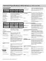
BUS HEALTH TEST MODE (Fluke 225C and 215C only)
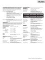
RECORDER MODE
Bus Health automatically analyzes the electrical signals on the industrial bus
system to measure individual parameters and to give waveform information.
Automatically compares the measurement results to preset values and present
‘good,‘weak’ or ’false’ indicator with each parameter.
SCOPE-RECORDROLL MODE
Source and display
Memory depth
Bus types and reference standards used:
AS-i (EN50295, 166 kb/s);
CAN-bus (ISO-11898, up to 1 Mb/s);
Modbus (EIA-232 up to 115 kb/s and EIA-485 up to 10 Mb/s);
Foundation Fieldbus H1 (61158 type 1, 31.25 kb/s) ;
Profibus DP (EIA-485 up to 10 Mb/s) and PA (61158 type 1,
31.25 kb/s);
Ethernet [10Base2 (coaxial) and 10BaseT (UTP)], 10 Mb/s;
Ethernet 100BaseT (100 Mb/s);
RS-232 (EIA-232, up to 115 kb/s);
RS-485 (EIA-485, up to 10 Mb/s).
Time base range
Recorded timespan
Glitch capture
Sample rate
Resolution
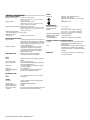
METER MODE
Horizontal scale
Zoom
Memory
OHMS
Ranges
Accuracy
5,000 counts
500mV, 5V, 50V, 500V, 1,000V
± (0.5 % + 5 counts)
± (1 % + 10 counts)
± (2.5 % + 15 counts)
± (1 % + 10 counts)
± (2.5 % + 15 counts)
500Ω, 5kΩ, 50kΩ, 500kΩ, 5MΩ, 30MΩ
± (0.6 % + 5 counts)
OTHER METER FUNCTIONS
Continuity
Beeper on < 50Ω (± 30Ω)
Diode test
Up to 2.8V
Amps
Adc, Aac, Aac+dc using an optional current clamp or
shunt. Scaling factors: 0.1 mV/A, 1 mV/A, ...
100 V/A and 400 mV/A
Temperature (°C, °F)
With optional accessories. Scale factors 1 °C/mV
or 1 °F/mV
Input impedance
1 MΩ ± 1% // 10 pF ± 2 pF
Advanced meter functions
Auto/manual ranging, relative measurements
(Zero reference), TrendPlot recording
5 ms/div to 1 min/div
6 sec to 24 hr
50 ns
20 MS/s
200 µsec to 2 sec
Recording modes
Stop-on-Trigger
(through External)
MAXIMUM RESOLUTION
VOLTMETER RANGES
ACCURACY
Vdc
Vac true rms
15 Hz...60 Hz:
60 Hz...1 kHz:
Vac+dc true rms
dc...60 Hz:
60 Hz...1 kHz:
Input A, Input B, Dual
27,500 points per input.
Each point consist of Min-Max pair.
Min-Max values are measured at high sample
rate ensuring capture and display of glitches.
Min-Max values
Measured parameters (where applicable):
Bias voltage level, signal amplitude, pulse width or baud rate,
risetime, fall time, jitter, signal distortion, noise HF, noise LF,
in-band noise.
Via 4 mm banana inputs. Fully isolated from scope inputs and scope ground. The
specified accuracy is valid over the temperature range 18 °C to 28 °C (65 °F to 82 °F).
Add 10 % of specified accuracy for each degree C below 18 °C or above 28 °C.
Dual input waveform storage mode.
Single sweep, continuous roll, Start-on-Trigger
(through external), Stop-on-Trigger (through
external)
ScopeRecord mode can be stopped by an
individual trigger event, or by an interruption of
a repetitive trigger signal.
Time from start, time of day
Up to 100x
Up to 2 dual input ScopeRecord waveforms can
be saved for later recall and analysis.
Single or dual input electronic paperless
chart recorder. Plots, displays and stores meter
and scope measurements.
Input A, Input B or DMM input
18,000 points record per input. Per record point
a minimum, a maximum and an average
value, plus a date- and timestamp are stored.
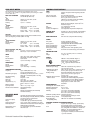
TRENDPLOT™
RECORDING
Source and display
Memory depth
Ranges
- normal view
- in view-all mode
(overview of total record)
Recorded timespan
Recording mode
Measurement speed
Horizontal scale
Zoom
Memory
2 min/div
48 hr
250 ns
4 MS/s
4.8 sec
5 s/div to 30 min/div
5 min/div to 48 hr/div
Up to 22 days with a resolution of 1
minute
Continuous roll for the duration of the
full recordable timespan
5 measurements per second or more
Time from start, time of day
Up to 64x zoom
Up to 2 TrendPlot recordings can be saved for
later recall and analysis.
CURSOR MEASUREMENTS - ALL RECORDER MODES
Source
Input A, B or DMM input
Dual vertical lines
Min-Max or Average voltage. Time between
cursors
Single vertical line
Min-Max or Average voltage. Absolute date and
time or time from start
Technical Datasheet Fluke ScopeMeters 3