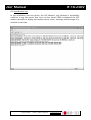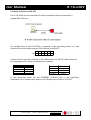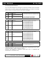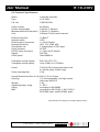
1
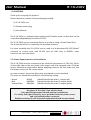
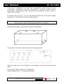
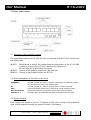
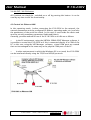
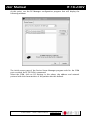
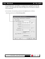
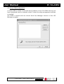
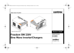
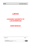
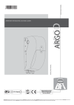
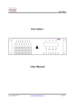
IF-18-230V
8 Schuko Sockets Controller Interface
User Manual
(English)
COMM-TEC GmbH
Siemensstr. 14
D-73066 Uhingen
Tel.: +49-7161-3000-0
Fax: +49-7161-3000-333
www.comm-tec.de
Version A0 - August 2006 / DBA
© Copyright by COMM-TEC
User Manual
IF-18-230V
INDEX
1.0 Overview
2.0 Power Requirements and Installation
3.0 Parts and Features
4.0 Control via Ethernet LAN
5.0 Relay Interface via RS-232
6.0 Communication Protocol
7.0 Connector PIN assignment
8.0 Technical Specifications
9.0 Warranty, Service and Returns Policy
Please read this manual carefully before installing the IF-18-230V.
COMM-TEC shall not be liable under any circumstances for consequential or
incidental damages and injuries including, but not limited to, labor costs or loss of
profits arising in connection with the use of or inability to use COMM-TEC
products.
COMM-TEC reserves the right to modify or discontinue designs, specifications,
warranties, and policies without notice.
COMM-TEC GMBH
SIEMENSSTRASSE 14
D-73066 UHINGEN
TELEFON +49(0)7161/3000-0
TELEFAX +49(0)7161/3000-333
WWW.COMM-TEC.DE
[email protected]
User Manual
IF-18-230V
1.0 OVERVIEW
Thank you for buying this product.
Please check the contents of the packaging carefully:
-
(1) IF-18-230V unit
-
(1) Schuko power plug
-
(1) User Manual
The IF-18-230V is a multiple socket outlet with 8 Schuko power outlets that can be
controlled independently via LAN or RS-232.
The IF-18-230V can be connected directly to a LAN or using a Virtual Serial Port.
The Virtual Serial Port is created by the provided software.
For more versatility the IF-18-230V can be used as a bi-directional RS-232/10baseT
converter to control units with RS-232 port via LAN (only in MODE1, other
functions are restricted then)
2.0 Power Requirements and Installation
The IF-18-230V must be connected to an electrical environment of 230 Volt, 50 Hz.
At the right side on the rear panel is the power cord with stripped ends. A Schuko
plug is enclosed for termination. Before applying power to the unit make sure that
the power source has the correct values.
In some countries, the power plug must be adapted to local standards.
The wires are identified according to the following coding:
- Brown
- Blue
- Yellow/Green
PHASE
NEUTRAL
GROUND
(Identified with the letter L, maybe red)
(Identified with the letter N, maybe black)
(Identified with the letter E, maybe green)
Caution
Be aware of the risks of an electric shock.
Only qualified personnel should perform installations.
For safety and signal integrity, use a grounded external power source
and a grounded power connector.
Reliable earthing of rack mounted equipment should be maintained.
COMM-TEC GMBH
SIEMENSSTRASSE 14
D-73066 UHINGEN
TELEFON +49(0)7161/3000-0
TELEFAX +49(0)7161/3000-333
WWW.COMM-TEC.DE
[email protected]
User Manual
IF-18-230V
If the unit is installed in a 19 Inch rack consideration should be given to an
environment compatible with the manufacturer’s maximum rated ambient
temperature. Avoid placing high heat-producing equipment directly above or
below the IF-18-230V.
In side the unit are 9 fuses - one for each Schuko (8) and one for the power supply
protection. If a fuse blows the unit must be opened.
Caution
Disconnect the the unit from power before it is opened.
Unscrew the 8 screws - the location is shown in the picture.
The positions of the fuses are shown in the following picture:
Open the black cap of the related fuse and replace it with the same type and
value.:
Power supply FUSE1: 5x20mm, T 500mA/250V
Schuko sockets FUSE 2 – 9: 5x20mm, 6A/250V.
COMM-TEC GMBH
SIEMENSSTRASSE 14
D-73066 UHINGEN
TELEFON +49(0)7161/3000-0
TELEFAX +49(0)7161/3000-333
WWW.COMM-TEC.DE
[email protected]
User Manual
IF-18-230V
3.0 Parts and Features
3.1 Selection of the operation mode
The operation mode of the IF-18-230V can be selected with the 6 DIP switches on
the front panel.
MODE 1: Setup Mode in which the communication parameters of the IF-18-230V
in relation to the LAN or RS-232 interfaces are defined or
RS-232/10baseT bi-directional converter.
MODE 2: Control of the Schuko sockets via LAN Ethernet
MODE 3: Control of the Schuko sockets via RS-232
3.2 Visual indications of the LEDs on the front
ETHERNET
Rx
RUN
RUN and STATUS
SCHUKO 1 - 8
red LED, normally off, lights if a collision is detected on the Ethernet network
and remains on as long as this condition lasts.
red LED, normally on, switches off when data is received from LAN
green LED, flashes shortly every 3 seconds in normal operationg mode
green LEDs, flashes in configuration phase (setup button pressed)
red LEDs, ON if the related Schuko outlet is energised; OFF if it is idle.
3.3 Schuko Sockets
Each socket can handle a load of 5 Ampere at 230 Volt, however the maximum
load of all 8 together should not exceed a total of 10 Ampere.
COMM-TEC GMBH
SIEMENSSTRASSE 14
D-73066 UHINGEN
TELEFON +49(0)7161/3000-0
TELEFAX +49(0)7161/3000-333
WWW.COMM-TEC.DE
[email protected]
User Manual
IF-18-230V
3.4 ALL OFF / ALL ON button
All 8 sockets can simply be switched on or off by pressing this button. It can be
used by any time to test the functionality.
4.0 Control via Ethernet LAN
In this operating mode, before connecting the IF-18-230V to the network, the
network parameters must be configured (IP address, operating mode, etc.) and also
the parameters of the serial line which, in this case, is used inside the device and
must be set with mandatory parameters (indicated below).
Generally, possible methods of use of the IF-18-230V on a LAN are as follows:
•
in the PC environment, using the VIRTUAL SERIAL PORT Manager software, it
is possible to control the IF-18-230V as if this is connected directly to a COM of the
PC. In this case, using the VSP Manager software, virtual COM ports are created
that can be managed in the same way as the physical COM ports of the PC.
•
In other environments in which the Windows OS is not used, the IF-18-230V
can be interfaced directly using the TCP/IP and UPD/IP protocols.
COMM-TEC GMBH
SIEMENSSTRASSE 14
D-73066 UHINGEN
TELEFON +49(0)7161/3000-0
TELEFAX +49(0)7161/3000-333
WWW.COMM-TEC.DE
[email protected]
User Manual
IF-18-230V
4.1 Configuration on Ethernet LAN
Configuration of the IF-18-230V for use in the PC environment using the VSP
Manager software to create virtual COMs is described below. The IF-18-230V is
configured via its serial port, connecting it to a PC on which the DS Manager
configuration software is installed.
Refer to Appendix A. Characteristics of the LAN connection for further details of
the meanings of the Ethernet configuration parameters and of operating mode. A
short outline of IF-18-230V configuration is provided below (for those already
acquainted with the problems of an Ethernet network).
First of all, set the IF-18-230V to MODE 1, the setup mode. Use the DIP-Switches at
the front panel to set the following configuration:
3
ON
1
4
5
6
2
Then connect the IF-18-230V to the PC with the configuration software using a
serial cable with the following pins connected (see chapter 7 as well):
PC
IF-18-230V
(Tx) 3
(Rx) 2
(Rx) 2
(Tx) 3
(GND) 5
(CTS) 8
(RTS) 7
(GND) 5
(RTS) 7
(CTS) 8
Switch the IF-18-230V on, wait a few seconds and press the SETUP button on the
rear panel of the IF-18-230V (the green RUN and STATUS LEDs start flashing).
Now the IF-18-230V is ready for a new configuration setup.
COMM-TEC GMBH
SIEMENSSTRASSE 14
D-73066 UHINGEN
TELEFON +49(0)7161/3000-0
TELEFAX +49(0)7161/3000-333
WWW.COMM-TEC.DE
[email protected]
User Manual
IF-18-230V
At this point, run the DS Manager configuration program that will display the
following window:
The initial screen page of the Device Server Manager program asks for the COM
port on which the IF-18-230V is connected.
Select the COM, click on DS Settings in this phase, the address and network
protocol with the characteristics of the packets must be defined.
COMM-TEC GMBH
SIEMENSSTRASSE 14
D-73066 UHINGEN
TELEFON +49(0)7161/3000-0
TELEFAX +49(0)7161/3000-333
WWW.COMM-TEC.DE
[email protected]
User Manual
IF-18-230V
In the example below, the IP address is set (this must be compatible with the type
of LAN in which the IF-18-230V will be installed) and no time-out is set on the TCP
session, i.e. the application that controls the relays of the IF-18-230V can maintain
control indefinitely
In this window, the mandatory parameter that must be set is as follows:
• Operating mode must be Slave Routing Mode
COMM-TEC GMBH
SIEMENSSTRASSE 14
D-73066 UHINGEN
TELEFON +49(0)7161/3000-0
TELEFAX +49(0)7161/3000-333
WWW.COMM-TEC.DE
[email protected]
User Manual
IF-18-230V
The packet characteristics setting window, Outbound packets, must be configured
as follows:
• The TCP packet is completed after the set time-out of 20 ms.
• Start and Stop characters must not be defined
COMM-TEC GMBH
SIEMENSSTRASSE 14
D-73066 UHINGEN
TELEFON +49(0)7161/3000-0
TELEFAX +49(0)7161/3000-333
WWW.COMM-TEC.DE
[email protected]
User Manual
IF-18-230V
The characteristics of the serial line, Serial Properties which, in this case, is used
internally and which must necessarily be configured with the following
parameters, are defined:
• Baud rate: 9600 bit/sec
• Parity: none
• Flow control: none
• Data bits: 8
At this point, the data can be confirmed and these will be sent to the IF-18-230V
where they will be saved with two consecutive OKs.
The configuration of the IF-18-230V is now complete and installation in the
network can be performed. To do this, switch off the IF-18-230V and set the mode
selection DIP-Switches to MODE 2 (control via Ethernet network):
1
ON
2
5
3
6
4
The IF-18-230V can now be connected to a port of the network hub .
In this operating mode, no cable must be connected on the serial port of the
IF-18-230V.
COMM-TEC GMBH
SIEMENSSTRASSE 14
D-73066 UHINGEN
TELEFON +49(0)7161/3000-0
TELEFAX +49(0)7161/3000-333
WWW.COMM-TEC.DE
[email protected]
User Manual
IF-18-230V
4.2 Virtual COM configuration
A virtual COM to which to associate the IP address of the IF-18-230V that has just
been configured must be created on the PC where the relay management software
is installed.
The COM is created with the Virtual Serial Port Manager function of the VSP
Manager program:
COMM-TEC GMBH
SIEMENSSTRASSE 14
D-73066 UHINGEN
TELEFON +49(0)7161/3000-0
TELEFAX +49(0)7161/3000-333
WWW.COMM-TEC.DE
[email protected]
User Manual
IF-18-230V
After clicking on Add VSP, the Properties screen page is displayed. Association is
performed indicating the number of the COM port that will be used by the
management program. Regarding the previously configured IF-18-230V, the type
of protocol, the IP address and the number of the Data Port used must be
indicated. See the example given below.
Confirm the data with 2 consecutive OKs. At this point, the SCHUKO socket
management software can interface the IF-18-230V via COM3 like with a standard
serial port really installed on the PC.
To manage the SCHUKO socket, start the IF-18-230V software included in the DST
(Device Server Toolkit) package or implement the protocol described in chapter 6
on the PC.
Note: after configuring the IF-18-230V and connecting this in the network, correct
functioning can be checked using the PING command. In the PC environment, this
is possible via the DOS prompt using, for the previous example, the ping
169.254.100.40 command
COMM-TEC GMBH
SIEMENSSTRASSE 14
D-73066 UHINGEN
TELEFON +49(0)7161/3000-0
TELEFAX +49(0)7161/3000-333
WWW.COMM-TEC.DE
[email protected]
User Manual
IF-18-230V
4.2 Port Monitor Log
In the installation and test phase, the VSP Monitor Log software is particularly
useful as it logs the events that occur on the virtual COMs configured; the VSP
makes it possible to display information about errors, warnings and messages in a
window in real time.
COMM-TEC GMBH
SIEMENSSTRASSE 14
D-73066 UHINGEN
TELEFON +49(0)7161/3000-0
TELEFAX +49(0)7161/3000-333
WWW.COMM-TEC.DE
[email protected]
User Manual
IF-18-230V
5.0 Relay Interface via RS-232
The IF-18-230V can be controlled via serial commands when connected to a
standard RS-232 port.
No configuration of the IF-18-230V is required in this operating mode. It is only
required to set the mode selection DIP-Switches to MODE 3:
1
2
3
4
ON
5
6
Connect serial controllers refering to the tables below for RS-232 cable connector
pin mapping and for serial communication settings:
BAUD
Data Bits
Stop Bit
Parity
Flow control
9600
8
1
NONE
NONE
PC
IF-18-230V
(Tx) 3
(Rx) 2
(Rx) 2
(Tx) 3
(GND) 5
(GND) 5
In this operating mode, the red ETHERNET (collision) LED is not significant;
remember not to connect any cable to the Ethernet port of the IF-18-230V.
COMM-TEC GMBH
SIEMENSSTRASSE 14
D-73066 UHINGEN
TELEFON +49(0)7161/3000-0
TELEFAX +49(0)7161/3000-333
WWW.COMM-TEC.DE
[email protected]
User Manual
IF-18-230V
6.0 Communication Protocol
The IF-18-230V manages the commands for driving the SCHUKO sockets (described
below) when it is set to serial or LAN operating mode. In transparent operating
mode, no type of command related to the relays is managed.
Status Request
Command: Response:
Ascii
D<CR>
D s1 s2 s3 s4 s5 s6 s7 s8
<CR>
Hex
44 0D
44 s1 s2 s3 s4 s5 s6 s7 s8
0D
C nr <CR> <ACK>
Hex
43 nr 0D
06
whereas:
nr indicates the SCHUKO socket number:
1 (hex 31) SCHUKO socket #1
2 (hex 32) SCHUKO socket #2
3 (hex 33) SCHUKO socket #3
4 (hex 34) SCHUKO socket #4
5 (hex 35) SCHUKO socket #5
6 (hex 36) SCHUKO socket #6
7 (hex 37) SCHUKO socket #7
8 (hex 38) SCHUKO socket #8
A (hex41) All SCHUKO sockets
Command: Response:
Ascii
O nr <CR> <ACK>
Hex
4F nr 0D
O (hex 4F) SCHUKO socket disabled
C (hex 43) SCHUKO socket enabled
whereas:
nr indicates the SCHUKO socket number:
1 (hex 31) SCHUKO socket #1
2 (hex 32) SCHUKO socket #2
3 (hex 33) SCHUKO socket #3
4 (hex 34) SCHUKO socket #4
5 (hex 35) SCHUKO socket #5
6 (hex 36) SCHUKO socket #6
7 (hex 37) SCHUKO socket #7
8 (hex 38) SCHUKO socket #8
A (hex41) All SCHUKO sockets
Command: Response:
Ascii
whereas:
s1...s8 indicates the state of the SCHUKO socket 1
to 8
06
ID Request
Ascii
Command: Response:
i <CR>
i U1 <CR>
Hex
69 0D
whereas:
69 55 31 0D
The IF-18-230V identification is U1
If the sent command is not correct (for example, due to transmission errors), the IF18-230V will reply a <NAK> character or Hex 15
Therefore, any sequence of characters closed with <CR> is considered and
interpreted as a command string.
COMM-TEC GMBH
SIEMENSSTRASSE 14
D-73066 UHINGEN
TELEFON +49(0)7161/3000-0
TELEFAX +49(0)7161/3000-333
WWW.COMM-TEC.DE
[email protected]
User Manual
IF-18-230V
7.0 Connector PIN assignment
Serial RS-232 port, 9pin Sub D female:
PIN
Signal
1
not connected
2
3
4
5
6
7
8
9
Rx
Tx
internally connected with pin 6
GND
internally connected with pin 4
RTS
CTS
not connected
Ethernet port 10BaseT, RJ-45 8pin female:
PIN
Signal
1
Tx+
2
3
4
5
6
7
8
TxRx+
not connected
not connected
Rxnot connected
not connected
Ethernet wiring:
Wiring between HUB + IF-18-230V
Side A
Side B
Wiring between two IF-18-230V
Side A
Side B
1
1
1
3
2
3
4
5
6
7
8
2
3
4
5
6
7
8
2
3
4
5
6
7
8
6
1
4
5
2
7
8
Note:
Wire 1 & 2 is a Twisted Pair
Wire 3 & 6 is a Twisted Pair
COMM-TEC GMBH
SIEMENSSTRASSE 14
D-73066 UHINGEN
TELEFON +49(0)7161/3000-0
TELEFAX +49(0)7161/3000-333
WWW.COMM-TEC.DE
[email protected]
User Manual
IF-18-230V
8.0 Technical Specifications
Name
Type
Cat.-No.
Controller Interface
IF-18-230V
708IF18-230V
Power outlets
Schuko load (single)
MaximumSchuko load (total)
Fuse
8x Schuko
230Volt / 5 Ampere
230Volt / 10 Ampere
5x20mm T 6A for each channel
Ethernet interface
Network cable
Ethernet Input connector
Network Protocols:
Data buffer size
Serial interface
RS-232 Input connector
Signals
Serial speed
10 Base T
CAT5
1x RJ-45 female
UDP, TCP, ICMP, ARP
2 independent of 255 bytes
RS-232
1x 9pin Sub D female
RxD TxD
fixed 9600 b/s
Transparent mode signals
Transparent mode speed
RxD, TxD, RTS, CTS
from 150b/s to 115200b/s
Power
230 Volt 50 Hz (external power cord
w/ Schuko plug, 2,80m long)
9 VA
Power consumption
Overall dimensions (W x H x D) 483 x 135 x 100 mm
Housing
19" rack mountable, 3ru high, metal,
slate grey RAL7015
Weight
3 kg
Operating temp. range
0 - 45°C
Safety
according to EN 60065
EMC
according to EN 55103-1, EN 55103-2,
EN 50081 part1 and EN 50082 part2
Specifications are subject to change without notice
COMM-TEC GMBH
SIEMENSSTRASSE 14
D-73066 UHINGEN
TELEFON +49(0)7161/3000-0
TELEFAX +49(0)7161/3000-333
WWW.COMM-TEC.DE
[email protected]
User Manual
IF-18-230V
9.0 Warranty, Service and Returns Policy
This product is under warranty for a period of two (2) years from the date of
purchase.
COMM-TEC’s liability and Buyer’s remedies under this warranty shall be limited
solely to repair of the faulty units free of charge.
This warranty does not apply if the product has been modified, repaired by an
unauthorized agent, or improperly installed, used, or maintained.
If a problem occurs first contact your dealer or COMM-TEC for trouble shooting.
If verification of a problem requires factory repair, ask COMM-TEC’s Customer
Equipment Service representative to issue a
Return Materials Authorization (RMA) number.
Merchandise will not be accepted without a RMA number.
When returning a product to COMM-TEC in Uhingen for repair please comply with
the following instructions:
• Shipping and insurance costs must be prepaid
• Use original shipping container(s), (if possible)
• Indicate the RMA number clearly on the outside of each container
• Enclose a written description of the problem
The under warranty repaired units will be returned Carriage Free to the sending
party (dealer or consumer).
Outside the warranty period, COMM-TEC will repair the faulty units, charging all
arising expenses of the repair e.g. labor, parts, transportation and insurance, to the
sending party (dealer or consumer).
For any problems during installation and operation of the IF-18-230V
call the COMM-TEC hotline +49 07161 3000-0,
send a fax +49 07161 3000-333
or e-mail to [email protected]
COMM-TEC GMBH
SIEMENSSTRASSE 14
D-73066 UHINGEN
TELEFON +49(0)7161/3000-0
TELEFAX +49(0)7161/3000-333
WWW.COMM-TEC.DE
[email protected]
User Manual
IF-18-230V
APPENDIX A. Characteristics of the LAN connection
A.1 LAN Port
The Ethernet port of the IF-18-230V is of the 10Base T type and, similarly to any other appliance, each
IF-18-230V has its own univocal Ethernet (MAC) Address and must have its own valid IP address in
order to function correctly in the network. The IF-18-230V has two logical ports, one that can be
defined by the user, called Data Port, used to exchange data with other network appliances, and a
predefined port, called Command Port, with a fixed address 65535 (FFFF hex), used to send the
programming of the IF-18-230V via the network.
The IF-18-230V can exchange data with remote stations using the TCP/IP or UDP/IP protocol
(according to the configuration of the Transport Protocol parameters) and can operate both as master
and slave. Other settings refer to the IP address, the address of the destination Data Port, the IP
address of the gateway, the NetMask and the connection time-out. In addition to the TCP and UDP
protocols, the IF-18-230V also supports ARP and ICMP (ping). This makes it possible to send a 'ping'
to any other appliance of the network in order to check effective connection.
A.2 RS232 Port
The serial port of the IF-18-230V supports TX, RX, CTS, and RTS signals and can work at baudrates
up to 115200. In Transparent Mode (MODE 1) the serial port transmits the data between the IF-18230V and attached serial device (microcontroller). In the Serial Programming Mode the port is used to
program the IF-18-230V’s Settings. Settings that define the operation of the serial port include the
Baudrate (150~115200bps), Parity (none, even, or odd), Bits Per Byte (7 or 8), and Flow Control
(none or CTS/RTS). Each of these Settings has a matching Parameter that overrides the value of a
corresponding Setting.
A.3 Routing Buffers
The data between the Ethernet port and the serial port is routed via two independent 255-byte buffers,
one for each routing direction. Buffers are necessary because the Ethernet and the serial port operate
at different speeds and in different ways. Ethernet carries the data in “packets” (i.e. groups of data),
while the serial port sends and receives a serial “stream” where each data byte is independent. Here
is how the IF-18-230V transforms the Ethernet packets into the serial stream and back:
• Ethernet serial data routing is simple: the IF-18-230V outputs the contents of arriving Ethernet data
packets byte by byte via the serial port. The IF-18-230V does not check of filter the contents of data
being routed in the Ethernet -> serial direction
• Serial Ethernet routing requires grouping arriving serial data into packets and is more complicated.
Several Settings define exactly what serial data is accepted into the buffer and when and how this
data is combined into an Ethernet packet and sent out. Detailed information on the subject can be
found in Serial -> Ethernet data routing.
A.4 Slave and Master routing modes
The IF-18-230V routes the data in one of two modes as defined by the Routing Mode Setting:
• In the Slave Routing Mode the IF-18-230V never sends any data transmission in the serial port ->
Ethernet direction before it receives some data from the remote station first (i.e. the data in the
Ethernet -> serial direction). The serial data received into the IF-18-230V’s serial port before the
remote station “contacts” the IF-18-230V is discarded. In the Slave Mode the IF-18-230V will “work”
with any station on the network that contacts it.
COMM-TEC GMBH
SIEMENSSTRASSE 14
D-73066 UHINGEN
TELEFON +49(0)7161/3000-0
TELEFAX +49(0)7161/3000-333
WWW.COMM-TEC.DE
[email protected]
User Manual
IF-18-230V
• In the Master Routing Mode the IF-18-230V does not wait for the remote station to send the data first
and routes the data in the serial -> Ethernet direction as soon as there is a data to be sent. The data is
always sent to a specific destination (as defined by the Destination IP-address and Destination Data
Port Number Settings of the IF-18-230V). Also, the IF-18-230V only accepts the data sent from the
remote station whose IP-address matches the one set in the Destination IP-address. The IF-18-230V
will discard the data sent from any other IP. Note, that data port number of the sender is not verified so
the data can be sent from any port.
A.4.1 Using Slave and Master Routing Modes
Use the Slave Routing Mode to network-enable serial devices that never send out the data by
themselves but instead are “polled” for data from the PC. Examples of such devices are time
recorders, access control panels and other “hardware terminals”.
Use the Master Routing Mode to network-enable serial devices that send out the data “spontaneously”
i.e. without waiting for the request from PC. Also use the Master Routing Mode in cases when the
serial data must flow independently in both directions (i.e. Ethernet -> serial and serial -> Ethernet).
This is the case, for instance, when you are creating a “network modem” that must pass the data in
both directions simultaneously.
A.4.2 Required network settings for the Slave and Master Routing Modes
In the Slave Routing Mode the IF-18-230V only “responds” to other stations on the network. When the
IF-18-230V receives the data from remote station it memorizes this station’s IP-address and data port
number. When routing the data in the serial -> Ethernet direction the IF-18-230V will reply to this IPaddress and data port number. Therefore, the only network settings that must be set in the Slave
Routing Mode are the IF-18-230V’s own IP-address and the Data Port Number. This is true even if
there is a router between the remote station and the IF-18-230V. You don’t have to set the Netmask
and Gateway IP when using the IF-18-230V in the Slave Routing Mode;
In the Master Routing Mode the IF-18-230V needs to be able to send the data to a predefined remote
station at any time. This means that not only IF-18-230V’s own IP-address and Data Port Number
must be set but also the Destination Ipaddress and the Destination Data Port Number. If the
destination remote station and the IF-18-230V are residing in different network segments then the
Netmask and Gateway IP-address must also be set.
A.4.3 Slave and Master routing modes vs. UDP/IP and TCP/IP transport protocols
UDP/IP and TCP/IP provide completely different data transmission so IF-18-230V’s behavior in the
Slave and Master Routing Modes is slightly different under UDP/IP and TCP/IP Transport Protocols.
• UDP/IP Transport Protocol
- Slave Routing Mode.
All UDP data packets arriving from any remote station and addressed to the Data Port of the IF-18230V are routed to the serial port. For the serial -> Ethernet direction the IF-18-230V always sends the
data to the IP-address and the port number that were received in the last (latest) UDP packet. Once
the IF-18-230V receives a UDP packet from a different station it will start sending all its serial ->
Ethernet data to this new station. After power up and before the IF-18-230V receives the first UDP
data packet the IF-18-230V doesn’t have any IP-address and port number to send the data to so all
the data received into the IF-18-230V’s serial port is simply discarded.
- Master Routing Mode.
The IF-18-230V only accepts and routes to the serial port the data packets that have originated from
the remote station whose IP-address matches the one defined by the Destination IP-address Setting.
Source data port number need not match the one defined by the Destination Data Port Number
Setting so the packet can be sent from any port. Whenever the IF-18-230V has the data to transmit in
the serial -> Ethernet direction it will send the data to the Destination IP-address and Destination Data
Port Number.
COMM-TEC GMBH
SIEMENSSTRASSE 14
D-73066 UHINGEN
TELEFON +49(0)7161/3000-0
TELEFAX +49(0)7161/3000-333
WWW.COMM-TEC.DE
[email protected]
User Manual
IF-18-230V
The packet will be sent to the Destination Data Port Number even if the packet received by the IF-18230V from the remote station originated at a different port. Therefore, it possible that the IF-18-230V
will be receiving the data from one port but sending it to another port!
• TCP/IP Transport Protocol
- Slave Routing Mode.
The IF-18-230V will accept an incoming TCP connection from any station on the network. The IF-18230V will not attempt to establish a connection with a remote station by itself even it the IF-18-230V
has the data to transmit in the serial -> Ethernet direction. Once the remote station has established the
connection the data can flow independently in either direction. Pending serial -> Ethernet data
received by the IF-18-230V prior to the TCP connection establishment is discarded when the
connection is established.
- Master Routing Mode.
The IF-18-230V will both accept an incoming TCP/IP connection and attempt to establish a connection
with the remote station by itself depending on which side sends that data first- remote station or
attached serial device. Incoming TCP connection will only be accepted from a station whose IPaddress matches the one defined by the Destination IP-address Setting of the IF-18-230V. Source
port number need not match the one defined by the Destination Data Port Number Setting so the
connection can be initiated from any port. When the IF-18-230V needs to initiate a TCP/IP connection
the it will attempt to connect to the Destination IP-address and Destination Data Port Number. Once
the connection has been established the data can flow independently in either direction. Note that
unlike in case of UDP/IP there will never be a situation when the IF-18-230V receives the data from
one port but sends the data to another port. Once the TCP/IP connection has been established both
sides exchange the data using a single port on each side.
A.4.4 Connections with more than two nodes
In many real-life situations it is often necessary to have several PCs (network stations) access the
same serial device through the IF-18-230V (“many clients to one data source”) or have many serial
devices (each connected to the network via its own IF-18-230V) send the data to a single PC (“many
data sources to one client”).
• Many clients to one data source operation is achieved by using the IF-18-230V in the Slave
Routing Mode. The IF-18-230V will reply to any sender in this mode, so any station will be able to
access the host serial device with the IF-18-230V inside.
- UDP/IP Transport Protocol should not be used if there is a chance that several different clients will
send the requests to the same IF-18-230V/serial device at the same time. Data mix up will result on
the serial side and the IF-18-230V won’t be able to route the data back to the respective sender of
each command correctly.
- TCP/IP Transport Protocol can be used safely since when one client is already connected to the IF18-230V others won’t be able to gain access to the same IF-18-230V until this client disconnects. To
prevent one client from holding the TCP/IP connection to the IF-18-230V indefinitely there is a
Connection Timeout Setting that defines after how long the IF-18-230V will abort the connection in
case there is no data transfer in any direction.
• Many data sources to one client operation is achieved by using the IF-18-230V in the Master
Routing Mode. In this mode the IF-18-230V will route all its serial -> Ethernet data to the Destination
IP-address and Destination Data Port Number. Any number of IF-18-230Vs can be set to send the
data to the same destination.
- UDP/IP Transport Protocol can be used in this arrangement but you must make sure that each serial
data block output by the serial device is sent out in a single UDP packet. Potential data mix up can
occur on the receiving end if the serial data block is transmitted in several UDP packets and several
IF-18-230V are sending data at the same time. The upside of using the UDP/IP is that you will only
need to maintain one listening socket on the receiving end to get the data from all data sources
(unless, of course, you want to distinguish between the data sources). Several IF-18-230V’s Settings
COMM-TEC GMBH
SIEMENSSTRASSE 14
D-73066 UHINGEN
TELEFON +49(0)7161/3000-0
TELEFAX +49(0)7161/3000-333
WWW.COMM-TEC.DE
[email protected]
User Manual
IF-18-230V
define how the incoming serial data is combined into Ethernet packets so you can make sure that the
serial data block from is not split into several packets (see serial -> Ethernet data routing for details).
- TCP/IP Transport Protocol can be used safely but you will have to maintain a separate socket on the
receiving end for every data source sending the data.
A.5 Serial to Ethernet data routing
The IF-18-230V provides a way to choose which incoming serial data is accepted into the serial ->
Ethernet buffer, how this data is combined into Ethernet packets and when it is sent out via the
Ethernet port.
The IF-18-230V treats all incoming serial data as a sequence of data blocks. The term “data block”
here does not mean that the IF-18-230V is only capable of working with a structured serial data. An
absolutely random serial stream can also be processed- as one continuous infinite serial data block.
Serial data blocks begin when a start condition is detected and end when a stop condition is detected.
After the start condition is detected the IF-18-230V begins recording the incoming serial data into the
serial -> Ethernet buffer. Thus, the start condition is said to open the serial data block. When the stop
condition is detected the IF-18-230V seizes recording the data into the buffer and attempts to send out
all the data accumulated in the buffer via the Ethernet port. Therefore, the stop condition closes the
serial data block. The inter-block serial data i.e. the data received after the stop condition is detected
and before the next start condition is detected is discarded. Besides the start and stop conditions there
is also a break condition. When the break condition is detected the IF-18-230V doesn’t close the serial
data block (i.e. it continues recording subsequent serial data into the serial -> Ethernet buffer) but
sends out the data already accumulated in the buffer through the Ethernet port. Break conditions
provide a way to subdivide large serial data blocks.
A.5.1 Start conditions
The Start On Any Character Setting defines if the IF-18-230V recognizes any character received into
the serial port as a start condition or requires a predefined Start Character to open the serial data
block.
When Start On Any Character is set to “yes” the IF-18-230V will accept any character following the
end of the previous serial data block as the beginning of the next block. When Start On Any Character
is set to “no” the IF-18-230V will only open the serial data block when one of the preset Start
Characters is received. Up to three different Start Characters can be defined. Start Characters
received after the serial data block has been opened are treated as normal characters and do not
“restart” the serial data block.
A.5.2 Stop conditions
Up to three different Stop Characters can be defined to close the serial data block. Once one of the
preset Stop Characters is detected the IF-18-230V closes the serial data block and attempts to send
out the contents of the serial -> Ethernet buffer via the Ethernet port. All subsequent serial data is
ignored until the next start condition is met. The use of Start Characters and Stop Characters assumes
that these characters will not be encountered in the data block body. Some communications protocols
use checksums (or other forms of data integrity verification). Checksum can potentially take any value
and occasionally match the ASCII codes of the Stop Characters. To avoid possible confusion some
communications protocols put the checksum bytes behind the Stop Characters. The IF-18-230V deals
with this by allowing to define a Number Of Post-characters for each enabled Stop Character. For
example, if the Number Of Post-characters for a certain Stop Character is set to 2 then the IF-18-230V
will additionally receive and count as belonging to the current serial data block 2 bytes of data after
this Stop Character has been encountered.
COMM-TEC GMBH
SIEMENSSTRASSE 14
D-73066 UHINGEN
TELEFON +49(0)7161/3000-0
TELEFAX +49(0)7161/3000-333
WWW.COMM-TEC.DE
[email protected]
User Manual
IF-18-230V
A.5.3 Break conditions
The Maximum Data Length Setting defines the maximum number of data bytes in the serial ->
Ethernet buffer. (can be set between 32 and 255). Once this number is reached the IF-18-230V
attempts to send out the contents of the buffer via the Ethernet port. This Setting only works when the
UDP/IP Transport Protocol is selected. This is because TCP/IP has its own way to determine what
size of data chunks is best for transmission over the network.
The Maximum Intercharacter Delay Setting defines the maximum time gap between the arrival of two
consecutive serial characters into the serial port (can be defined in 10ms increments between 10ms
and 2.55 sec). Once this time is exceeded the IF-18-230V attempt to send out the contents of the
serial -> Ethernet buffer via the Ethernet port. Setting the maximum Intercharacter Delay to 0 disables
the function.
A.5.4 Default configuration
The default configuration is the follow:
• Start On Any Character
• no Stop Characters are defined
• Maximum Intercharacter Delay is 10 ms
• Maximum Data Length is 255 byte (UDP only).
As a result the very first byte received into the serial port is regarded as a beginning of the serial data
block that never ends. Once there amount of data in the serial -> Ethernet buffer reaches the limit or
there is a gap in the serial transmission the IF-18-230V combines all serial data it has already received
and sends it out. Practice shows that this arrangement works very well not only for a random data flow
but also for structured data.
A.5.5 Buffer-related issues
When using the IF-18-230V be careful not to overflow its internal Ethernet -> serial and serial ->
Ethernet buffers. The overflow can occur because of the difference in receive/transmission speeds on
the Ethernet and the serial sides of the IF-18-230V (Red Status LED blinks momentarily when
overflow happens). In addition, the internal receiving buffer of the host serial device can potentially
overflow if the IF-18-230V outputs the serial data too fast.
• Ethernet -> Serial buffer
- UDP/IP Transport Protocol. The Ethernet -> serial buffer can easily overflow because the Ethernet is
much faster than the serial port and UDP/IP has no inbuilt protection against buffer overflows. UDP/IP
should not be used to send continuous data flow and is only suitable for sending short data blocks that
can fit in the buffer.
- TCP/IP Transport Protocol has an inbuilt protection from buffer overflowing. You can safely send the
data of any size.
• Serial -> Ethernet buffer
the only way to protect the buffer is to enable the RTS/CTS Flow Control in the IF-18-230V and on the
host serial device. This way the IF-18-230V will be able to signal the host serial device to stop
transmitting the data once the buffer becomes full.
• Internal receiving buffer of the host serial device.
this buffer can also be protected by using the RTS/CTS to regulate the exchange of data between the
IF-18-230V and the serial device.
Note:
Using TCP/IP and RTS/CTS is the most reliable way of transmitting data through the IF-18-230V.
COMM-TEC GMBH
SIEMENSSTRASSE 14
D-73066 UHINGEN
TELEFON +49(0)7161/3000-0
TELEFAX +49(0)7161/3000-333
WWW.COMM-TEC.DE
[email protected]