1
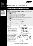
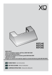
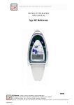
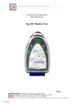
User Manual
OSD168 H1 & H2 On Screen Display
OSD168 H1
OSD168 H2 (it takes label LRS)
ADOSD168GPS Adapter OSD168-GPS
GPS5HZADOSD GPS 5Hz + Adapter OSD168
RC Systems
V:3.4
20-9-2008
OSD168
The OSD168 is a On Screen Display, system of presentation of texts and semigraphs in oriented
screen mainly to visualize the instrumentation and data of flight in airplanes, helicopters and other systems
of radio control in modality FPV or in Guided Vehicles Independent UAV' s.
Applications: Aeromodelling FPV, UAVs, radio control, robotics, aerial photography, video and much
more.
The module on prints the different variables in screen, mixing a signal of video with the data. The video
signal is the video camera in the airplane either a source of video the PAL or NTCS (under demand).
OSD168 is designed for general use in 35Mhz, 41Mhz, 2.4Ghz and for new system LRS (long Range
Systems) of emitting-receiving of 868-902Mhz, he is compatible with the bus for radio control, RCBUS of
DMD.
The concept of the OSD168 is double:
On the one hand he is compatible with any system FPV and by another one…
Different from the present one when connecting itself to the RCBUS and to work with the system of
868Mhz with virtual instruments.
Diagram in blocks OSD168 (the different connections are something according to version H1 or H2)
The OSD168 is thought like a OSD of low cost, small size and only 11grms of weight, but without
trimming possibilities. It is more than sufficient to fly FPV with the necessary data….and something more.
It is fed 5Vcc. Maximum 6Vcc. If they are used peripheral external as an altimeter agrees that the
tension is stable (TIME or DCDC to 5Vcc+-5%).
It has 9 connectors RC standard of 3 pins, that allow the peripheral connection of manifold, like
measurement of two batteries, current with a modern sensor of effect hall, until 20Amp in H1 Version and
30Amp in H2, altimeter, Fail Safe, etc. Including an exit for a buzzer for sonorous alarms and indications.
It can work like a text Terminal/semigraphical receiving commands by the serial port or RCBus.
Reason why the field of use and use is enormous.
The entrance of the altimeter is analogical, with a sensitivity of 0,604 mV/meter.
It is possible to be used GPS for aid to navigation, to be seen the distance of the airplane, speed,
coordinates, return to the base, etc. using the adapters to GPS available at the moment:
ADOSD168GPS: Economic. To that already they have a module GPS and they wish to take advantage
of it.
GPS5HZADOSD: With a modern GPS of 5Hz SanNav including.
OSD168 BEGINNING AND USE
A connected time all the electrical system, we can happen to prove the equipment. If it does not use
GPS can prove it within house, if it uses GPS will have to prove in the outside where the GPS can catch
satellites.
The initial test is only necessary to verify that the equipment is working correctly and is wiring well. In
order to fly it is not necessary to see the messages of beginning.
Initial test OSD168:
Activate the receiver of video and a monitor or the glasses of video.
Connect the batteries of the airplane and póngase the glasses immediately.
It will verify the initial messages of the OSD168, having identified the versions of the video processor
and firmware of the microcontroller.
Later it verifies as it calibrates initially the barometric altimeter, takes only two or three seconds, once
finished must give to an altitude = 0 +-1m. The calibration usually gives at level of the sea offset of 200
300m. This is offset internal of the altimeter and is correct, to these meters is necessary to add the altitude
where are you. (1850m máx. Total).
Altimeter is barometric reason why if it changes the atmospheric pressure by changes of the time while
it flies, is normal that it changes to something reference 0 of the ground. Téngalo in account at the time of
landing. In the long cases of abrupt change of time and flights, it can have differences of up to 10 M.s The
habitual thing is +-4m if the time is moderately stable and in most of flights it must be +-2m.
If in flight it sees that the measurement of the barometric altimeter is unstable, can mechanically be
due to a defective feeding of 5V not stabilized either due to a problem in the TIME of the variador or a
defective regulator or excessive servo defective one or blocked consumption on the part of servo or the
some. ( To never connect the direct battery to +5V although is of 6V, could permanently damage the OSD
and the altimeter). If a Li-Po of 11.1V uses, can use a DCDC24/5RC of DMD to stabilize the voltage to 5V
and in addition to save consumption in the battery. At the outset with the TIME it must be sufficient.
Verify the voltages of the batteries and no that no activated alarm are
Verify if the buzzer with beeps works initial and if the sound is transmitted by the microphone. (It
verifies that the connector of the video glasses corresponds with the one of the receiver).
If it uses GPS:
It will be able to see the initial message and version of the system of GPS in half of the screen.
Continuation the system looks for the GPS and their speed of communication (38K4 or 4K8b) the first
time that connects a GPS to the Adapter, the this active system autobaud until finding it and records the
parameters in non-volatile memory automatically.
If the GPS does not communicate with the adapter or there is no GPS is possible to be seen every 4
seconds as the GPS changes to the system autobaud of speed looking for.
When the GPS communicates correctly they appear the amount above of satellites ( normally 0), to the
right, that indicates that the GPS communicates with the adapter and this with the OSD.
To start off of the OSD it hopes here to that the GPS catches satellites and gives valid positions. This
can take depending on the GPS and if it has battery that memorice the constellation of satellites.
If it has battery as the GPS5HADOSD the starting always is in hot and takes about 10 to 15 seconds.
If it does not have battery as the ADOSD168GPS and you do not twist a battery to him (with diode in
series or she explodes) to your GPS EM-406 (for example) the starting is in cold and can take up to two
minutes according to the zone.
A time the OSD receives positions been worth of the GPS, will visualize the coordinates of the present
position and will establish the lift-off point. This operation can take seconds depending on the speed of
refreshment of the GPS.
A time the starting point of takeoff establishes the OSD (Base or Home), will erase the screen and will
begin to visualize the rest of data like speed, distance, course, Degrees and arrow of return to the base.
He is already ready to take off.
Remember that the coordinates will disappear as soon as elevates to the airplane to more of 50m if is
close.
IMPROVEMENTS OSD168 H2 Version
The circuit of the OSD168 H2 more is advanced than the one of the previous version H1. It has less
components to make the same functions.
The most important improvements are the system of video and the ammeter. Let us see the differences:
OSD168 H1 Version:
It attenuates to the low brightness and the level of synchronisms TV, with which some receivers of video
with diversity get to exchange badly when the reception signal is low.
Some recording video with low signal of video restricted copy” or similar messages get to stop the
recording indicating “, had the low level of synchronisms.
If the OSD168 is dull or without feeding voltage the video does not work.
It needs a voluminous condenser to separate CC video.
Ammeter with limit in 20A, in some cases remains short.
In order to measure the main battery or of the motor one it was necessary to twist from the pin +Bat1 to
+ of the ammeter.
OSD168 H2 Version:
It does not attenuate brightness.
It changes level of video neither of synchronisms, single adds text or graphical to the video.
The video works although the OSD168 H2 is dull or without voltage.
The electronic circuit needs less components and small size but.
Ammeter for 30A and 35A of tip.
The system connections has been redistributed better of.
The pin takes off +Bat1 and outer wiring is connected internally to the ammeter, avoiding.
Improvement in the levels of signal of the RCBus.
Measurement of the voltage of work of 5V. Warning “Warning: Vcc=4.6 “, when the low voltage of 4,7 or
raises 5.3V. Indicating some problem, as failures in regulator (TIME) either DCDC or overload of damaged
consumption due to a servo one have clogged mechanically.
Screens OSD168
Video:
PAL, 1Vpp input. 75 Ohms.
Example of parameters shown in OSD168 H1, with receiver 869Mhz taken in R+D.
Example of image of video in flight with receiver 869Mhz and GPS
Characteristics OSD168
Low Cost:
Good relation price-characteristics
Video:
The PAL, 1Vpp input/output. 75 Ohms. NTCS under demand.
Characters:
32 Horizontal x 16 Lines. Text and graphic characters.
Power supply:
5V +-5%, 50mA.
Firmware:
Flash eprom 16Kb. load in factory by ISP.
Data in screen:
Received data blocks (only LRS 869-902Mhz)
Receiving DBms. Quality reception. (only LRS 869-902Mhz)
Visual alarms and sonorous plots, dBm and Fail safe dBm (Only LRS 869-902Mhz)
Voltage of battery 1
Low alarm battery1. Line of vision and sonant
Voltage of battery 2.
Low alarm battery 2. Line of vision and sonant
Flight time.
Instantaneous amperes (internal sensor 20Amp either 30Amp in H2, tips of 25Amp or 35Amp)
Mah. consumed milliamperes/hour
altimeter (optional sensor of barometric pressure, until 1850m).
Fail safe from receiving servo exit. Visual and sonorous alarm.
Data of GPS:
Entrance GPS by port series with adapter to 38400b or 4800b standard NMEA.
Present position (according to height and distance).
Height (GPS) annuls barometric to start off of 1700m. (V 3.5)
Distance to the base.
Speed with respect to earth.
Course in degrees
Position airplane in degrees
Direction of return of the base.
Reserved entrance CH1 to calibrate sensors voltage and intensity.
Function of Terminal ASCII, in order to use it by other equipment or to connect it to a microcontroller
external and to use its own software.
It is connected to the RCBus port as if outside a port entrance series TTL.
Speed port series: 115.200b, 8, N, 1
Erased commando screen: 18d
Commandos of positioned cursor (X, and): 27, X (1-32d), and (1-16d)
Size: 25 xs 50mm. Weight circuit: 11 grms
Alarms:
Battery 1 (motor) low. (Auto-element 2-3)
Battery 2 (video) low. (Auto-element 2-3 and is not if there is no battery)
Minimum RSSI.
Data blocks reception OK, minims.
dBms reception minimum
Fail safe from receiving servo exit. Visual and sonorous alarm.
Warning of low Voltage in +5V from 4.7V and high voltage from 5.3V in H2 Version
It visualizes position GPS when this below certain height according to distance.
(<50m to 1km, <100m to 2Km, <150m to 4Km, <200m to 8Km, <250m to 12Km, <300m to 15Km)
Connections OSD168
WARNING: To verify hardware version before twisting, the H2 version comes identified with blue label LRS. The
conexionado one is something different..
Power Suplly:
5V. From the receiver.
Equipment 35Mhz -2.4Ghz: Connector 7 (PPM/AUX, +5V, 0V) to the channel of the receiver with fail
programming safe.
Equipment 869Mhz: Connector 3 or 4 (RCBus, +5V, 0V) to the Rcbus of the receiver.
A cable is necessary female-female, for the connection of the receiving-OSD.
Video:
PAL. 75 Ohms 1Vpp. NTCS under demand.
Connector 1 (Video In, Out Video, 0V). Connect the exit of the video camera to the pin Video In.
Out Video when coming out connects the entrance of the video emitter
0V (GND) to 0V of the camera and the emitter of video connects the pin.
It needs to use a cable with female connector for the video wiring.
It does not forget that if is not in power On, the OSD168 (only H1 Version), it will not visualize anything
in the video.
RCBus:
Only for Adapter GPS and/or receivers of 869-902Mhz. Connectors 3 and 4
This cable has several functions: to feed the OSD168 from the receiver, to communicate the receiver with the
OSD and to communicate the adapter of the GPS.
If it has a receiver of 35Mhz or 2,4Ghz does not have to use it, safe for the adapter of the GPS.
Connectors 3 and 4 are identical and serve to make of bridge to connect futures equipment with RCBus (GPS,
etc.).
A cable is necessary female-female, for the connection of the receiving-OSD.
Connections OSD168. GPS
GPS with adapter ADOSD168GPS:
If you already have a standard module GPS NMEA compatible type EM406 either FV-M8 or, can
connect it through adapter GPS-OSD ref.: ADOSD168GPS. Speed RX GPS: 4800 or 38400bauds.
According to it indicates the label the female connector to the RCBus of the OSD and the male
to the GPS.
A cable with connector RC must make standard female for the GPS with the connect one:
RX (yellow or white), +5V (red) and 0V (black).
In order to protect its GPS of a bad accidental connection, it can in series place a R of 1K in
cable RX (yellow).
Connectors 3 or 4. Consider that the feeding of the GPS is provided from male connector RC 5Vcc.
It needs to use a cable with female connector for the wiring of the GPS and in some cases some
stretcher of servo.
GPS with adapter GPS5HZADOSD:
If you already have a OSD168 and wishes to add a modern and powerful GPS of 5Hz, this is a good
option. It does not need to update firmware of the OSD168. Compatible with the Version H1 and H2 of the
OSD168.
To connect the cable to the RCBus of the OSD.
Note: The electronics of the adapters is the same one, with the only difference that this takes
the GPS including
Connections OSD168
Buzzer:
Optional sonorous Sindicador. Not including.
In connector 2 a buzzer can connector (if it uses one different one from the one of DMD, are used single two pins: +5V
and Beep in H1 version and 0V and Beep in H2 version) Warning: Not to change the buzzers between versions, can
damage the OSD and generate an excessive and unnecessary consumption of battery.
In equipment that does not take to microphone in the emitter of 2.4Ghz or that is desired to directly connect the acoustic
system of alarms without buzzer, it can use a cable with female connector and connect the Beep exit to the sound entrance
of the emitter. Possibly it will need a potentiometer 1K and a condenser of 100nf to connect the circuits and to fit the volume.
It needs to use a buzzer with cable female or a cable with female connector.
Altimeter:
Sensor of barometric pressure, (optional and not including).
It is connected in connector 5. Black cable in 0V. If the voltage uses altimeter must be stabilized to 5V with DCDC,
regulating BEC or linear regulator type 7805 or similar.
The sensor does not have to be pressed by the rest of the equipment and it does not have to undergo blows or
unnecessary vibrations. It must go within the airplane in a site that does not receive pressure of the air of entrance in flight,
normally along with the receiver and servo it is a good site. Peak altitude: 1850m. If it takes GPS it can use the altimeter of
the GPS if it does not have the barometric one and if it exceeds 1850m of altitude activates the GPS altimeter automatically
(only in H2 version).
It needs to use altímetro_1A or GPS.
Fail Safe:
Entrance for detection Fail Safe. Only for receivers of 35Mhz and 2,4Ghz.
H1 version: It is connected in connector 7. (PPM/AUX, +5V, 0V)
H2 version: It is connected in connector 8. (ICP, +5V, 0V)
From connector 7 or 8 according to version to the channel of the
receiver with fail programming safe. At the same time which it
provides the information of the Fail Safe, it feeds the DCDC from the
receiver.
The Fail safe activates when the signal of the pulse of the servo
one is greater of 1.7mseg.
This obtains with an auxiliary channel of the receiver,
programming the fail safe of the receiver in the position that causes
the alarm.
It causes a message in the screen “Fail Safe” and one alarms
sonant with three beeps followed.
Sometimes, this sound can help to find the airplane lost.
A cable is necessary female-female, for the connection of the
receiving-OSD.
Connections OSD168
Voltmeters: They measure the voltage of the equipment batteries.
H1 version: Connector 9 (+Bat1 (motor), +Bat2 (video), 0V), Connects 0V to the negative of the battery of
the motor. +Bat1 to the positive of the battery of the motor. If the system does not make this connection it will
be giving to a continuous alarm of motor battery loss.
H2 version: In order to measure the battery of the motor it does not need connection some. She is internal
and it is connected directly to the positive of the ammeter. If it does not use the ammeter it must connect at least
the positive to + of the battery. If it does not connect of one or another form + of the main battery or motor, the
system will be giving a continuous alarm of battery.
In version 2, connector 9 is different of the H1 version (+Bat2 (bat video), +5V, 0V) it is here where it must
connect the video battery if it uses it. WARNING! Not to connect the pin of +5V of connector 9 to +12V of
the battery, the OSD will be destroyed immediately and it does not cover the guarantee. If it has doubts it
can connect it the first time with a resistance of 1K in series to prove. Below the OSD it has a label with the
connections.
The alarm is programmed automatically according to I number of cells (LIPO) of battery 2 or 3. The alarm
level is 6.6V for two elements and 10V for 3 elements.
Battery of video: The video battery is optional and if it is not used can leave to the pin +Bat2, without
connecting. It is car element and in addition it detects at the outset if there is or nonbattery with which it
does not sound the alarm if there is no battery. The pin +Bat2 must be connected to the positive of the
video battery.
CH1, 2.3 (H1) or CH1, +5V, 0V (H2):
Auxiliary entrances.
It is not used in flight.
It is used to recalibrate the sensors of current and voltage in the beginning being bypassed CH1 and 0V.
WARNING: It does not use it. Unless the voltmeters work bad or they are descalibrated and you have the
sufficient knowledge and equipment for your correct use. The instructions of calibration are more ahead.
They are used in the H1 version. This connector is not protected. Have precaution. If it injects voltage
by error here, the microprocessor will be damaged and this failure is not covered by the guarantee.
Ammeter:
They measure the current of the battery of the motor or the one of video.
A modern sensor of Effect Hall up to 20 Amperes, peaky of 25Amp in the H1 version and 30Amp of 35Amp
peak in H2 version, one is in charge to measure the current of the battery.
The ammeter has two cables of Red and black color in the part opposed to the connectors.
WARNING: IT DOES NOT CONNECT IT IN PARALLEL TO THE BATTERY, IS A SHORT CIRCUIT AND
DAMAGE THE OSD168.
One is due to connect in series with the ESC of the motor. That is to say, between + of the battery (red
cable) and + of the ESC of the motor (black cable).
If by some reason the Maxim current is surpassed fully allowed the ammeter of the OSD it can be unsuitable
and to even burn itself besides to run the risk of damaging the OSD.
The ammeter in series connects with the positive of the battery and the rest of the equipment. That is
to say, cable + (red) of the OSD168 goes to the positive of the battery (póngale the connector that now has
the positive of the ESC) and the positive of the ESC sold to blue or the black one of the OSD168, protect
with heat Shrink tube.
SP2+5V, 0V (H2):
auxiliary input. It is not used at the moment.
Connections OSD168 H1 version
Scheme typical connections in a system LRS of 869-902 Mhz with two batteries:
Scheme typical connections in a system of 35 Mhz H1 version:
Conexionado OSD168 H2 version for LRS 869-902Mhz
Scheme typical connections in a system LRS of 869-902 Mhz with two batteries:
Scheme typical connections in a system LRS of 869-902 Mhz with a battery:
Connections OSD168 H2 version for system 35-72Mhz
Scheme typical connections in a system of 35 Mhz or 72 Mhz H2 version with two batteries:
Scheme typical connections in a system of 35 Mhz or 72 Mhz H2 version with a battery:
GPS5HZASDOSD. GPS 5Hz + Adapter OSD168
GPS FV-M8 5Hz + Adapter OSD168 for systems of 869-902Mhz or 35Mhz. OSD168 not including.
I modulate GPS with the adapter for the OSD168 and pounds everything integrated and ready to
connect to the RCBus of the OSD.
If you already have a OSD168 and wishes to add a modern and powerful GPS of 5Hz, this is a good
option.
It is not necessary to update firmware of the OSD168. Compatible with the Version H1 and H2 of the
OSD168.
Parameters new GPS in OSD168:
- Distance in meters to the base, until 99.999m
- Speed with respect to earth in km. /hour
- Satellites (0-9, To… F).
- Course in degrees with text attendance (N, NE, S,… etc.)
- Position of the airplane with respect to the base in degrees (It
serves to orient the antennas of the base accurately)
- Indicating arrow of return to the base.
- Coordinates of GPS, only visible according to the height and
distance to the base. Useful to track the video before a loss.
Basic characteristicses :
- Compatible with systems LRS of 869-902Mhz and standard systems RC of 35, 72 and 2.4Ghz.
- GPS FV-M8 SanNAV to 5Hz, 32 channels and ceramic antenna. Precision: 2,6 to 3.3 meters.
- Supply: 3.3 to 5Vcc +-5%
- Consumptions: 80mA cold start, 65mA hot starting, 55ma to 20min.
- Battery Lithium 3V/220mAh for fast starting in hot, including.
- Size: 55x35x25mm
- Weight: 43grms
- Comunnications: RCBus to 115200b.
Connections:
To connect the cable to the RCBus of the OSD.
Note: The electronics of the adapters is the same one, with the only difference that this takes the GPS
including.
ADOSD168GPS. Adapter OSD168 to GPS NMEA Standard
Adapter GPS-OSD168 for systems of 869-902Mhz or 35Mhz, 2.4Ghz. GPS and OSD168 not
including.
If you already have a OSD168 and I modulate GPS and wishes to integrate it in its equipment, this is
an economic option that takes advantage of its previous purchases.
It is not necessary to update firmware of the OSD168. Compatible with the version H1 and H2 of the
OSD168.
Parameters new GPS in OSD168:
• Distance in meters to the base, until 99.999m
• Speed with respect to earth in Km/h
• Satellites (0-9, TO… F).
• Course in degrees with text (N, NE, S,… etc.)
• Position of the airplane with respect to the base in
degrees (It serves to orient the antennas of the base
accurately)
• Indicating arrow of return to the base (Return to Home).
• Coordinates of GPS, only visible according to the height
and distance to the base. Useful to track the video before a
loss.
Basic characteristicses:
• Compatible with systems LRS of 869-902Mhz and standard systems RC of 35, 72 and 2.4Ghz.
• Compatible GPS: FV-M8 and EM406 and in general any standard NMEA that works to 4800b or to
38400b.
• Supply: 5Vcc +-5% for GPS EM406 and 3,3 to 5Vcc for GPS FV-M8.
• Consumption: 18mA.
• Battery Lithium for fast starting in hot, NOT including.
• Size: 42x32x15mm
• Weight: 20grms
• Communications: RCBus to 115200b.
Connections:
According to it indicates the label the female connector to the
RCBus of the OSD and the male to the GPS.
A cable with connector RC must make standard female for the
GPS with the conexionado one: RX (yellow or white), +5V (red) and
0V (black).
In order to protect its GPS of a bad accidental connection,
it can in series place a R of 1K in cable RX (yellow).
Peripheral and extensions OSD168
GPS5HZADOSD. GPS 5Hz + Adapter OSD168
GPS FV-M8 5Hz + Adapter OSD168 for systems of 869-902Mhz or 35Mhz. OSD168 not including. If you
already have a OSD168 and wishes to add a modern and powerful GPS of 5Hz, this is a good option.
ADOSD168GPS. Standard adapter OSD168 to GPS NMEA, RCBus
Adapter GPS-OSD168 for systems of 869-902Mhz or 35Mhz, 2.4Ghz. GPS and OSD168 not including.
altímetro_1A.
Small and effective altimeter with analogical output 0.604mV/meter. Supply to 5Vcc. With connector for
aeromodelling.
It is calibrated automatically when the OSD starts up.
Resolution in OSD168: 1,5 meters. Max. altitude: 1850m. Peak altitude: 1850m- Altitude
Peripheral and extensions OSD168
Buzzer.
The buzzer (not including) serves to acoustic alert of alarms and important events in the OSD168. The
buzzers with blue color are compatible with the version H1 of the OSD168 and those of black color with
the H2 version of the OSD168.
In systems FPV if it is not desired buzzer or is wanted to save weight, the exit of beep by means of a
atenuador with two resistance or a potentiometer, and a condenser of 100NF to the entrance of the video
emitter can be connected.
Female-Female cable for Rcbus or entrance Fail Safe.
It is necessary to feed it and to remove the maximum yield in the systems from 869-902Mhz from DMD. It is a
standard connector for RC. (Not including).
Adjustment of brightness with cameras that saturate targets in H1 Version
The OSD168 H1 Version, low a 15% or but the total brightness of video so that their texts shine the
maximum and exceed to the signal of entrance of the camera., but it happens that if the camera sends a
greater signal of the standardized one, the effect of shaded around the text in the OSD and the target of
the text is confused with the white bottom of video. The H2 version, does not modify the brightness nor the
synchronisms in the video. The video works with the dull OSD.
Like seeing images saturated in target by the camera:
When you have a camera like MHQ36, that it saturates targets in the blue sky and prevents to see the
text of the OSD168, the problem with a simple adjustable potentiometer of 100 Ohms with the video signal
can be corrected in series. It is a form very simple and economic to fit the brightness. Also a resistance of
10, 22, 33, 47, 68, 82 ohms can be put in series to lower the brightness.
These changes, if there is diversity, can affect to the sensitivity of he himself. With the H2 version
diversity is not affected.
To see in the photos (1 and 2), the difference. It is possible to be fit darker by assumption, but it is
necessary to think as one will see when it is made at night. Also day in extreme cases could be put an
interrupting day / night.
Improvements in the text of the OSD168
Here a test of the OSD168 with the bottom of the darkest letters can be seen and greater resistance in the targets
of the letters.
Test made without changing the brightness of the camera and saturating in targets the zone of data OSD. (Photo
3). A little but brightness in the letters can be appreciated and shades but dark.
Calibration Voltmeters and ammeter H1 version
The adjustment of the voltmeters of the batteries and the local Ammeter, it can make same you.
Please it uses this adjustment only if it has the suitable knowledge and only in case of necessity, if it
detects and he is sure that the OSD168 has been descalibrated or, does not measure the real data.
Preparation of the calibration:
It will need a power supply stabilized to 12.0V/100mA.
It is important that it measures 12.0V and the precision is better of 10mV (can make sure with a digital
multimeter). In extreme cases it can use a source with a regulator 7812 that provides 12V +-5%. He will
always be better to have a approximate measurement that none.
It will need a regulated and limitable power supply that provides 5 Amperes and can limit the
consumption in short circuit in 5.0Amp. Verify before connecting to the sensor of current of the OSD168
that limits correctly and there are no problems.
If it has doubts, please IT DOES NOT FOLLOW AHEAD, it looks for an electronic technician or better
sends the equipment to DMD for its adjustment without risks.
Procedure of calibration for H1 Version:
Stop the OSD168.
Connect the power supply of 12.0Vcc to the two entrances of battery. 0V to the negative, +Bat1 and
+Bat2 to the positive in parallel.
It still does not connect the source of 5 Amperes.
Connect a pin of +5V through a R of 100 Ohms to 1K to entrance CH1.
Start up the OSD168.
Observe that the process of calibration of the voltmeters begins automatically and indicates it in
screen.
When finishing, it will begin to calibrate the ammeter and soon after the buzzer will toot.
Connect the power supply limited 5.0Amperios and 1V-3V approx To cables of the sensor of current of
the OSD168. Verify the consumption of the source if it is necessary with a digital ammeter.
Clear the pin of entrance CH1.
Verify that the continuous calibration and in seconds will have finalized.
When the calibration finishes, the measures of the voltmeters must be 12.0V, 12.0V and 5.0A in the
ammeter.
If the power supplies are variable, can change the voltage from 3 16V to verify that the voltmeters
measure correctly.
If the current source is adjustable, proves to change the limitation from 1Amp, to 5 or 10Amp if it
arrives, to verify the measurement of the ammeter.
End of the calibration.
The DMD TEAM, wishes the best flights him
For more frequent information and questions, it visits www.dmd.es or in the forums:
www.aeromodelismovirtual.com or www.rcgroups.com . It can see videos of real flight and some with
instructions of use and beginning in www.youtube.com or in www.Vimeo.com looking for (TRON FPV),
also it can find links to the videos in www.dmd.es
H1 Version
H2 Version
Design by tron. Made in Europe.
RC Systems
C/ Federico García Lorca, 5
46136 Museros (Valencia)
Spain - Europe
Telephone attention to the client: 615185077 only Spanish
Web: www.dmd.es
www.dmdopen.com
Emails: [email protected], [email protected], [email protected]
©Digital Micro Devices 2007, 2008
The mentioned marks are it for a reason or purpose informative, being property of their legal recorders.
Digitalis Micro Devices (DMD) does not offer any guarantee on the use of this product to exception of the
guarantees standard of the company that detail in DMD terms and conditions located in the page Web of DMD.
DMD does not assume any responsibility by the errors that can appear in this document and it reserves to the
right of change of the devices either the specifications that are detailed at any time and without previous warning nor
has no commitment to update this information. Neither clear licenses or any other intellectual property of DMD are
granted surroundings a the sale of DMD products, specifically or by implication. The DMD products are not authorized
for the use like critical components in equipment in which the life depends on the people. DMD declines all
responsibility by the use that the user does of this module.