1
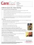
2
Release
Hydroprojekt CZ, a.s.
WINPLAN software package for designing and drawing of water supply and wastewater
systems
VSV-ENGINEERING s.r.o.
Plastic Sewer
Manholes and
inspection
chambers
WINPLAN
software package for designing and drawing of water supply
and wastewater systems
User’s manual of
Plastic Sewer Manholes
and Inspection Chambers 2005 (v. 2.0)
© 1995 – 2005 Hydroprojekt CZ, a.s.
Táborská 31 • 140 16 Praha 4
Phone +420 261 102 497 • Fax +420 261 215 186
Internet http://WWW.HYDROPROJEKT.CZ/WINPLAN
E-mail [email protected]
Plastic Sewer Manholes and Inspection Chambers 2005 (Release. 2.0)
User’s manual
Contents
User’s manual of ...................................................................................................................................................... 1
Plastic Sewer Manholes ........................................................................................................................................... 1
and Inspection Chambers 2005 (v. 2.0) ................................................................................................................... 1
1
Foreword .......................................................................................................................................................... 4
2
Requirements for hardware and software, installation...................................................................................... 6
3
Initial description of the program ...................................................................................................................... 6
4
Inputs and outputs of the program.................................................................................................................... 8
5
Working with the program................................................................................................................................. 9
5.1
6
Description of menus, buttons and dialog windows commands...................................................................... 12
6.1
6.2
6.3
6.4
6.5
6.6
6.7
6.8
6.9
7
Limiting conditions ....................................................................................................................................................... 11
File Menu ..................................................................................................................................................................... 13
Edit Menu..................................................................................................................................................................... 17
Tools Menu .................................................................................................................................................................. 20
View Menu ................................................................................................................................................................... 27
Help Menu.................................................................................................................................................................... 29
Manufacturer of manholes and inspection chambers .................................................................................................. 30
Left-hand side - list of manholes/inspection chambers files ........................................................................................ 30
Table ............................................................................................................................................................................ 31
Editing dialog ............................................................................................................................................................... 32
Description and general rules of sewer manholes assembly.......................................................................... 34
Page 2
WINPLAN
Plastic Sewer Manholes and Inspection Chambers 2005 (Release. 2.0)
Page 3
User’s manual
WINPLAN
Plastic Sewer Manholes and Inspection Chambers 2005 (Release. 2.0)
User’s manual
1 Foreword
Dear friends,
the "PLASTIC SEWER MANHOLES AND INSPECTION CHAMBERS 2005 (v. ´2.0)“ program, which
comes to your hands, is the new version of program, which complements popular and abundantly used
program for concrete manholes "PRECAST SEWER MANHOLES". Besides current production catalogues
of the manufacturer Wavin this new version offers anew also a language version of the program.
Simultaneously with this program inclusion of next manufacturer of plastic manholes is prepared and the
"PLASTIC SEWER GULLIES" program is being developed as well.
All these programs continue to be the components of the WINPLAN system software package for
designing and drawing of water supply and wastewater systems (particularly pipe lines) on PCs in Microsoft
Windows. The particular programs of this package may be used independently (they have autonomous
inputs and outputs).
If you are the owner of the program ”free version” only, which is distributed to designers and project
planners as a service of companies like Wavin and Bocr (under preparation), within the promotion of their
products, you do not need the hardware key (hardlock) for the program running. However, you do not have
the possibility to load automatically the data from a longitudinal profile of sewer processed in the WINPLAN
system. This function is a feature of the ”full version” only, which is sold and distributed by
Hydroprojekt CZ. With the ”free version” you have to enter all the necessary data via keyboard or with help
of a mouse. Concerning the program outputs all the versions are equivalent. In the free versions of course
the products of one company only are listed – these of the company distributing the program.
The overall structure of the WINPLAN software system is obvious best from the following block
diagram. The rectangles represent the particular modules of the system (programs); the arrows then
represent their links at cooperation and sharing the data.
Page 4
WINPLAN
Plastic Sewer Manholes and Inspection Chambers 2005 (Release. 2.0)
User’s manual
HYDRONet
MAPPING
ODULA
SCHEMATIC
LONGITUDINAL
PROFILE
ROUTE
DIGITAL TERRAIN
MODEL
SEWER SYSTEM
LONGITUDINAL
PROFILE
WATER SUPPLY
SYSTEM
LONGITUDINAL
SEWER MANHOLES
AND INSPECTION
CHAMBERS
WATER SYSTEM
ASSEMBLY
SCHEME LAYOUT
All information on software (sale and user support) are provided by the Hydroinformatics Team of
Hydroprojekt CZ, a.s., Táborská 31, 140 16 Praha 4. The basic data on programs may be found on the
following web site: www.hydroprojekt.cz/Winplan/. To send inquiries and requests for information the
[email protected] e-mail address may be used. Telephonic information may be obtained at phone
number +420 261 102 497 or facsimile number +420 261 215 186.
The software system elaborators’ team would be grateful for any of your suggestions, inquiries and
comments, which might help to the system improvement or extension. We wish you a pleasant and
efficient work with our tools.
Page 5
WINPLAN
Plastic Sewer Manholes and Inspection Chambers 2005 (Release. 2.0)
User’s manual
2 Requirements for hardware and software,
installation
The ”PLASTIC SEWER MANHOLES AND INSPECTION CHAMBERS 2005” program of the
WINPLAN SW package is designed for the MS Windows 98 and higher PC operation systems. The
program has no special demands on hardware. The graphic card should enable operation of Windows with
at least 800 x 600 resolution at 16 colours.
The installation to hard disc from the attached CD is run automatically by the SETUP.EXE installation
program, which is easily started by a double click of the left mouse button on program name in the "File
manager" or in the "Explorer". The Install-Shield Wizard will lead you through the installation. You would be
asked to select and prove the program location and the program folder. The Wizard offers a standard
setting, which is satisfactory in a majority of cases.
3 Initial description of the program
The ”PLASTIC SEWER MANHOLES AND INSPECTION CHAMBERS 2005” program is intended for
design of plastic sewer manholes and inspection chambers produced by the Wavin company. Downloading
of relevant data from the „Sewer System longitudinal profile“ program of the WINPLAN SW system data
files is possible.
The main purpose of the program is to create the model drawings of a selected type of sewer
manholes and inspection chambers, manhole and inspection chamber assembly schemes created by the
program, table of manhole and inspection chamber elements, table of drop-manhole elements and “in situ”
connections, table of base elements and covers. These tables comprise the detailed data for the parts
(elements) ordering and for detailed design of the projects. Further the program enables to create an order
of the shaft elements including covers. The “full version” enables also loading of relevant data from the files
of longitudinal profile within the WINPLAN system.
User’s interface of the program is divided into 4 parts:
The main roll-down menu with the program title, with quick access keys (buttons) and manufacturer
selection
Left-hand panel, where all the manholes are synoptically shown in all open data files
Table in bottom part of a screen, with detailed data of each manhole (table of manholes, table of base
elements,..)
Editing dialog with data of the currently designed manhole and its schematic sketch.
The program enables working with more files simultaneously. Each file has an own editing window
with data and schematic sketch of the currently designed manhole. Switching among them is possible
Page 6
WINPLAN
Plastic Sewer Manholes and Inspection Chambers 2005 (Release. 2.0)
User’s manual
either via the „View“ main menu by selection of relevant window, or by clicking of the left mouse button at
any manhole of the required file in the left-hand panel, or by clicking of the right mouse button at file name.
The user also may select the editing windows arrangement into tiles or cascade in the „View“ menu and
then move by pointing to the desired working editing window by the mouse.
Page 7
WINPLAN
Plastic Sewer Manholes and Inspection Chambers 2005 (Release. 2.0)
User’s manual
4 Inputs and outputs of the program
Program inputs:
Besides the standard opening of the .SPL file the program enables loading of both the .SEW file of
the „SEWER LONGITUDINAL PROFILE release 4.0“ and .SXML file of the „SEWER LONGITUDINAL
PROFILE release 5.0“ programs.
Program outputs:
A) Output to data file:
.SPL
- data file of the PLASTIC SEWER MANHOLES AND
INSPECTION CHAMBERS program
(maximum number of manholes in one file is not
limited)
.DXF
- drawing data file of the CAD programs (a “package”
type file, which cannot be opened directly, see export
to DXF)
B)
Output to printer:
(in A4 landscape format)
- print of the model drawings
- print of the manholes and inspection chambers
(shaft elements) table
- print of the base elements table
- print of manholes assemblies
- print of drop-manholes table and „in situ“
- print of covers table
(in A4 portrait format)
- order of shaft elements incl. base elements, covers
Page 8
WINPLAN
Plastic Sewer Manholes and Inspection Chambers 2005 (Release. 2.0)
User’s manual
5 Working with the program
Working with the „PLASTIC SEWER MANHOLES AND INSPECTION CHAMBERS“ program at
design of manholes is described in this chapter. Working in particular dialog windows is a topic of following
chapters.
User of the full version will select the manufacturer and executes downloading (importing) of
longitudinal profile data and adjustment of data errors consequently (“File” Menu) or he/she may submit the
particular manholes data in the editing dialog. User of a free version must submit all the manholes in the
editing dialog.
The submitting of manholes itself proceeds as follows. The user creates a new file by pressing
a button or selecting „New“ command in “File” menu. A new editing window appears. Then in the quickaccess keys bar a manufacturer is selected. This data is common for all manholes of the given file. Then a
new manhole may be inserted and its data submitted. The „New manhole“ button in the editing dialog
inserts the manhole. Program asks for sequence and identification of the manhole. Each manhole must
have an unambiguous sequence number. The sequence number determines sequence of the manhole in a
file. Identification of the manholes is arbitrary and it may be repeated within the framework of one file.
Identification must not be empty. The program checks whether a manhole with identical serial number
exists. If so, the program offers insertion of a manhole with a shift of the following manholes numbering. It
is possible to change the identification anytime later. After insertion of the manhole the sequence may be
modified only by the manhole shifting to other position with help of a mouse in the left-hand panel (by „drag
and drop“ function). Then the program asks for a new identification and sequence of the manhole. If no
manhole was inserted, the dialog editing fields are inaccessible.
Submitting proceeds by submitting of the outlet elevation (internal pipe bottom) of base element and
ground elevation (terrain) and the manhole terrain ground super-elevation when relevant. The elevations
may be relative (negative measured from terrain). It is also possible to submit the elevation differences only
and the program will calculate the ground level automatically. Simultaneously with submitting the program
calculates height of the manhole (sum of the used elements heights), ideal height of a manhole (difference
of elevations submitted plus the ground super-elevation when relevant). If the editing is correct, a manhole
schematic sketch appears also after each modification. At an incorrect editing the schematic sketch
disappears, at the same time an error message appears in the status line of the editing window (e.g.
„manhole is too high “).
After editing of level conditions the user selects the piping material. Based on the selected material
the list of existing outlet DN is updated. The program offers the existing combinations only.
Then the user selects the type of base element. The program offers all manufacturer’s options for the
combination of DN and material. There are two ways of selection of the base element type; selection in the
“Type of the base element” dialog or by ticking of particular connections together with settings of
corresponding connection angles. The program checks the input data again and it offers the manufactured
Page 9
WINPLAN
Plastic Sewer Manholes and Inspection Chambers 2005 (Release. 2.0)
User’s manual
base element types only. In case the required combination of piping material, DN and angle correspond to
any manufactured type a schematic sketch of base element appears. If such combination do not exist the
schematic sketch is crossed out with red lines.
Once the base element type is edited correctly the user selects a manhole cover in the „Cover
Selection“ dialog opened by pressing of relevant button. The manhole/inspection chamber may be left
without any cover, then it is necessary to tick „Without cover“ option, otherwise the program reports an
error („Wrong cover“).
The program enables editing of up to three drop-connections into one drop-manhole. After ticking the
„Drop-manhole“ box with relevant connection the „Entry and correction of drop-manhole” dialog window is
called by pressing of „Drop-manhole“ button. In the dialog the drop-manhole DN and the piping bottom
height from the outlet bottom of base element are determined. The program checks whether the dropmanhole does not mouth into a base element or into a joint of two shaft elements.
The program enables editing of up to three „in situ“ connections through the corresponding editing
dialog.
All changes of the manhole/inspection chamber data are immediately projected into all tables. The
current manhole may be changed anytime by mouse pointing and clicking to its identification in the lefthand panel or by pressing of the „Previous manhole/inspection chamber“ or „Next manhole/inspection
chamber“ quick-access keys. With the current shaft the program enables to return in submitting to arbitrary
preceding step („Undo“ and „Redo“ buttons). Once the current manhole is replaced with another all
sequence preceding submitting steps is deleted.
The user may possibly change the set of elements of automatically assembled manhole/inspection
chamber after ticking the „Individual assembly“ box in the editing dialog. The user may arbitrarily change
sequence
and
assembly
of
elements
of
manhole/inspection
chamber
in
dialog
„Individual
manhole/inspection chamber assembly“. The program checks the link between individual components only.
Similarly, the height of manhole shaft of small diameter may be modified by pressing the corresponding
button. Before leaving the dialog the program asks, whether it may change the manhole height of the
current manhole to a value calculated based on the individual assembly.
The user will inspect the composition of automatically assembled drop-manholes, checks and adjusts
them. He will carry out a comprehensive check of the all manholes/inspection chambers. He will inspect
the drawings and tables, print the drawings, tables, orders.
The procedure of individual assembly:
The program enables as well using of other options of data editing apart from the traditional way:
1/ The individual assembly of manhole/inspection chamber DN 1000.
This option is used for editing of automatically assembled manholes/inspection chambers. If the arrow
is pointing at the particular element – the element can be replaced or deleted If the arrow is pointing to the
gap between two elements, the another chosen element can be added.
Page 10
WINPLAN
Plastic Sewer Manholes and Inspection Chambers 2005 (Release. 2.0)
User’s manual
2/ Placing and ordering of an atypical base element production for manholes DN 600 and DN 1000
using the corresponding option in the dialog together with submitting of such connection angles, which do
not comply with the standard production catalogue.
3/ Individual specification of the manhole shaft height. When the option “Change height of the shaft” is
ticked the shaft height may be modified by switching the arrows in dialog. However the height must be the
multiple of “lengths given by possible cutting interval of pipe”. The interrelation between the
manhole/inspection chamber actual height and the ideal height could be influenced with this approach.
5.1
Limiting conditions
The program enables designing of plastic sewer manholes and inspection chambers with internal
diameter of DN 315 and DN 425 for piping ranges from DN 110 to DN 450 and sewer manholes with
internal diameter of DN 600 and DN 1000 for piping ranges from DN 160 to DN 400.
Maximum depth of a manhole without professional structural engineering assessment for DN 315,
425 and 600 corresponds to maximum shaft length of 6 m or similarly 5 m for DN 1000. (The program
enables to design even deeper manholes – up to 15 m.)
The minimum manhole heights corresponds to the minimum structural height of particular
manhole/inspection chamber type.
Maximum amount of the piping mouthed into a manhole base element is one outlet, the 1st
connection (main) and secondary connections Nos. 2 and 3.
Minimum amount of the piping mouthed into a manhole base element is outlet only, at a terminal
manhole/inspection chamber option.
Delta H for plastic base elements is insignificant or 0 mm.
Axe angles of the connections (against the outlet) acc. to manhole clock must be within 90° to 270°
range. The counter-direction junction is not admissible. Arrangement of all connections with respect to
selected profiles of piping must be such to prevent overlapping of the individual piping including relevant
inserts, and to ensure sufficient gaps among inserts, enabling the manhole base element manufacturing.
Program checks the spatial arrangement of connections acc. to selected material.
The shaft heights are limited with the cutting interval of shaft pipe; 55 mm for shafts of DN 315,
75 mm for shafts of DN 425, 100 mm for shafts of DN 600. The lowest shaft of DN 1000 is 125 mm high.
Page 11
WINPLAN
Plastic Sewer Manholes and Inspection Chambers 2005 (Release. 2.0)
User’s manual
6 Description of menus, buttons and dialog windows
commands
Fig. 1 – user’s interface of the “Plastic Sewer Manholes and inspection chambers 2005” program
Controlling of the program proceeds in the basic user’s interface of the application, i.e. in the
“MANHOLES/INSPECTIONS CHAMBERS DATA” window. The current *.SPL file name appears on the
left-hand side of the window name in the main title.
In the main menu there are standard commands for working with data (“File” menu), commands for
editing of data (“Edit” menu and “Tools” menu), commands for working with windows (“View” menu) and
commands for calling of help (“Help” menu). A majority of commands has also the quick access buttons.
Among the buttons there is a roll-down menu for selection of a manufacturer common for the whole file.
The editing dialog with data of the currently designed manhole/inspection chamber and its
schematic drawing is in the centre of working area. If there is no manhole/inspection chamber in the file, all
the editing fields are inactive.
The left-hand panel displays the open data files with all inserted manholes/inspection chambers.
The particular print outputs (tables) are scheduled and displayed in a table in bottom part of the
screen.
Page 12
WINPLAN
Plastic Sewer Manholes and Inspection Chambers 2005 (Release. 2.0)
6.1
User’s manual
File Menu
Items of the "File" menu serve for working with the manholes data files, for setting of an empty data
file for insertion of new data, for loading (importing) of longitudinal profile data, for printing of results, for
selection of a current printer for print preview and for the program termination.
Fig. 2 –File menu
New:
It will clear down the data of the current data file and assign a name to a new
data file [WITHOUT NAME.SPL]. The user is informed on the necessity to
save changes of the current file data.
Open:
It will clear down the data of the current data file (the user is informed on the
necessity to save changes of the data). With help of a standard dialog window
a selection of the required data file is enabled.
Close:
The current data file is closed and removed from the left-hand panel (the user
is informed on the necessity to save changes of the data).
Page 13
WINPLAN
Plastic Sewer Manholes and Inspection Chambers 2005 (Release. 2.0)
User’s manual
Save:
It saves the current data file to disc. If the command is selected with a new
data file, the “Save under name” command is switched automatically.
Save as:
It saves to disc the current data file under the user name with help of
a standard dialog window. This command is used at first saving of a file or at
creation of mutations of the existing files.
Import into the new file:
The program enables importing of data from the „ LONGITUDINAL PROFILE
OF SEWER“ program of the WINPLAN system. The new file containing
loaded data is created.
The program will load the selected .SEW or .SXML data file with help of
a dialog.
The program will report the amount of manholes loaded. In further dialog it will
list the manholes/inspection chambers, those that must be adjusted or deleted
are marked with an asterisk.
It is always necessary for all manholes to check and adjust the piping material
to a material, which is in the offer = it corresponds to the catalogue of
manufacturer selected before the data importing.
It is necessary to correct all the reported errors, to enable the program work
with
the
data.
The
most
frequently reported
error
is
a
too
low
manhole/inspection chamber or wrongly determined axe angle of connection.
Too big delta h is not monitored during the data loading. It must be corrected
consequently, or the particular manhole with big delta h must be designed as
a drop-manhole. If in the longitudinal profile no different elevations of the
outlet base element and the 1st connection (drop-manhole) are submitted, the
delta h is determined automatically as a sum of the manhole/inspection
chamber radii multiplied by longitudinal gradient in the sections upstream and
downstream the manhole/inspection chamber.
This dialog is not part in so-called ”free version”, which is distributed free-ofcharge. With the ”free version” you have to submit all the necessary data from
the keyboard or with help of a mouse.
Page 14
WINPLAN
Plastic Sewer Manholes and Inspection Chambers 2005 (Release. 2.0)
User’s manual
Import into the active file:
The program enables importing of data from the „ SEWER LONGITUDINAL
PROFILE“ program of the WINPLAN system. In this case the relevant loaded
data are added next the currently edited manhole of the active file.
The program will load the selected .SEW or .SXML data file with help of
a dialog.
The program will report the amount of manholes/inspection chambers loaded.
In further dialog it will list the manholes, those that must be adjusted or
deleted are marked with an asterisk.
It is always necessary for all manholes to check and adjust the piping material
to a material, which is in the offer = it corresponds to the catalogue of
manufacturer selected before the data importing.
It is necessary to correct all the reported errors, to enable the program work
with
the
data.
The
most
frequently reported
error
is
a
too
low
manhole/inspection chamber or wrongly determined axe angle of connection.
Too big delta h is not monitored during the data loading. It must be corrected
consequently, or the particular manhole with big delta h must be designed as
a drop-manhole. If in the longitudinal profile no different elevations of the
outlet base element and the 1st connection (drop-manhole) are submitted, the
delta h is determined automatically as a sum of the manhole radii multiplied by
longitudinal gradient in the sections upstream and downstream the manhole.
This dialog is not part in so-called ”free version”, which is distributed free-ofcharge. With the ”free version” you have to submit all the necessary data from
the keyboard or with help of a mouse.
Export of tables into MS Excel format:
Fig. 3 – dialog for export of manhole/inspection chamber into Excel
Page 15
WINPLAN
Plastic Sewer Manholes and Inspection Chambers 2005 (Release. 2.0)
User’s manual
The command enables export of selected tables into MS Excel format.
Printer setup:
Fig. 4 – dialog for printer setup
Dialog enables selection of a printer and setting of printing options (orientation
of paper etc.). The program automatically sets the orientation of print for
printing of tables and for printing of orders. We do not recommend changing
this setting.
Preview and print of tables:
Fig. 5 – dialog for selection of schedules and tables for printing
Page 16
WINPLAN
Plastic Sewer Manholes and Inspection Chambers 2005 (Release. 2.0)
User’s manual
By ticking in relevant boxes of dialog window it is possible to select, which of
the pages will be printed or browsed. Model drawings and size tables may be
browsed and printed always. Other if the program does not detect any error in
data only.
The outputs appear on the screen in the same format, in which they will be
printed. It is possible to print any page both independently and all together
from the browsing dialog.
Preview and printing of the order:
The order of the manhole/inspection chamber elements incl. covers appears
on the screen in the same format, in which it will be printed. It is possible to
print any page both independently and all together from the browsing dialog.
Send by E-mail:
It enables to send the current data as an attachment of a message. After
selection of this command the window for writing of a message with attached
file of current data appears.
Exit:
It terminates the program run in a legal way with an inquiry concerning saving
of the modifications carried out in the data file.
6.2
Edit Menu
Items of the "Edit" menu serve for recalling of particular dialog windows, in which it is possible to submit the
data of a current manhole or information on the designer or they enable a check of the submitted data.
Fig. 6 – Edit menu
Page 17
WINPLAN
Plastic Sewer Manholes and Inspection Chambers 2005 (Release. 2.0)
User’s manual
Undo:
The
command
will
delete
recent
modifications
made
in
current
manhole/inspection chambers data (step backward).
Redo:
The command will do again the modification recently cancelled by “Undo”
command in current manhole data (step forward).
Insert the new manhole/inspection chamber:
Fig. 7 – dialog for insertion of a new manhole
The command will insert the new manhole/inspection chamber into the data
file. In the dialog we submit the sequence and identification.
Delete the manhole:
Fig. 8 – dialog for deletion of the manhole
The command will delete current manhole/inspection chamber from the data
file.
Next manhole:
Previous manhole:
The commands enable to list in the sequence of manholes in the opened file
and to set the selected manhole as the current one.
Page 18
WINPLAN
Plastic Sewer Manholes and Inspection Chambers 2005 (Release. 2.0)
User’s manual
Project and designer data:
Fig. 9 – dialog for inserting of project and designer data
Common data for identification card of drawings and tables.
Order product list:
Fig. 10 – dialog containing a product list for order
A dialog will appear, in which all the products and elements used in the current
file are listed. The user may modify the list (erase lines, change amount of
pieces).
Page 19
WINPLAN
Plastic Sewer Manholes and Inspection Chambers 2005 (Release. 2.0)
User’s manual
Customer order data:
Fig. 11 – dialog containing customer data for order
Common data for order will be completed.
6.3
Tools Menu
Fig. 12 – Tools menu
Page 20
WINPLAN
Plastic Sewer Manholes and Inspection Chambers 2005 (Release. 2.0)
User’s manual
Base element selection:
Fig. 13 – Dialog of the base element type selection
The selection is done by marking of corresponding base element type. The
program offers the manufactured types only. Dialog is recalled from the
Editing dialog by
button.
Cover selection:
Fig. 14 – dialog of the covers selection
Page 21
WINPLAN
Plastic Sewer Manholes and Inspection Chambers 2005 (Release. 2.0)
User’s manual
Highlighting of relevant line carries out selection of the cover. Dialog is
recalled from the Editing dialog by
button.
Individual assembly:
Fig. 15 – dialog for individual assembly of a manhole/inspection chamber
The tool is accessible after ticking the „Individual assembly“ box in the
manhole submitting dialog only. In the dialog, which appears, it is possible to
assemble the current manhole from all available elements of the
manufacturer. The logical link among elements used is not checked. After
pressing of the OK button it is checked only, whether the elements link to each
other (if the upper width of the element is similar with the width of the next
element below). In case the set is not all right, the user must adjust it. It is
possible to change height of the manhole by individual assembly (design). The
user is informed on the change of height and if he/she does not agree, he/she
may adjust the set. It is possible to recall the dialog directly from the Editing
dialog by
button located to the right from the individual assembly tick box.
Page 22
WINPLAN
Plastic Sewer Manholes and Inspection Chambers 2005 (Release. 2.0)
User’s manual
In the beginning of using the “Individual Assembly” dialog the automatic
design of the manhole/inspection chamber will be displayed.
In the dialog it is possible to change the assembly of the manhole with help of
buttons acc. to individual idea by re-writing, editing from the catalogue and
also by erasing of particular elements of the automatically created manhole
(with exception of the base element). Arrow in the manhole assembly always
indicates the upper part of the element.
The "Move up" and "Move down" buttons serve for moving of selected
element up or down. The element is selected when the sign „“ points
towards it.
The „“ and „“ buttons serve for shift of the cursor, indicating to elements,
upwards and downwards.
The „Replace“ button replaces the active element (indicated by cursor) with
the element selected in the right-hand part of the dialog (catalogue).
The „Delete“ button will erase the element indicated by cursor.
The „Insert“ button will insert the element selected in the right-hand part of the
dialog.
The „OK“ button will confirm changes and close the dialog; the “Cancel” button
will revoke the changes and close the dialog.
Page 23
WINPLAN
Plastic Sewer Manholes and Inspection Chambers 2005 (Release. 2.0)
User’s manual
Entry and correction of drop-manhole:
Fig. 16 – dialog for entry and correction of a drop-manhole data
The item is only available in case of ticking at least one „drop-manhole“ box
next to connections in the manhole submitting dialog. In the dialog, which will
appear, it is possible to submit DN of a drop-manhole connection and height
measured from the outlet bottom. The program checks, whether the dropmanhole connection is not in the base element or in two elements joint. The
dialog may be recalled directly from the Editing dialog by a button.
If the delta h (determined or counted from the longitudinal profile) is bigger
than difference of the base element height and a sum of outlet DN and the
minimum mouthing of insert below the base element edge (150 mm), it is
necessary to mark this manhole in the editing dialog in relevant connection as
a drop-manhole (tick the "drop-manhole" box) and to solve it as a dropmanhole. Then the delta h becomes the H height of the drop-manhole and the
program does not report a wrong data of big delta h. Here DN of connection is
DN1, DN2 and dh is selected.
The automatically assembled drop-manhole will be displayed.
Page 24
WINPLAN
Plastic Sewer Manholes and Inspection Chambers 2005 (Release. 2.0)
User’s manual
The manhole will be displayed even when the basic data are submitted
wrongly; it is necessary to carry out a check from the editing dialog.
By the "Check" button it is necessary !!! to check correctness of the outlet
junction to shafts and/or to replace the shaft elements (always after switching
to individual assembly dialog), or to change H. The automatic assembly does
not monitor correctness of the connection pipe junction into the shaft element.
Manholes/inspection chambers overall check-up:
Fig. 17 – dialog for manholes overall check-up
Fig. 18 – dialog for manholes overall check-up
Information on shortcomings and errors is provided here. At wrongly
(insufficiently) completed data the program will not print relevant outputs –
tables. The correction of data is necessary or defect manholes must be
deleted. The errors may be represented by the manhole data, drop-manhole
or in case no cover is selected. (If you want to design a manhole without
cover, it must be identified as such).
Renumbering of manholes:
The program will re-number the submitted manholes starting from 1.
Page 25
WINPLAN
Plastic Sewer Manholes and Inspection Chambers 2005 (Release. 2.0)
User’s manual
Options:
Fig. 19– dialog for setting of the program options
The user will determine in the dialog, whether:
- Shaft elements at automatic assembly will be sequenced from the lowest
or from the highest one
- Data files will be opened with new program start
Further the program language and printouts language will be set here
Page 26
WINPLAN
Plastic Sewer Manholes and Inspection Chambers 2005 (Release. 2.0)
6.4
User’s manual
View Menu
Fig. 20 – View menu
Cascade:
After selection the opened dialog windows will be arranged in a form of
a cascade.
The windows horizontally:
After selection the opened dialog windows will be arranged in a form of
horizontal windows.
The windows vertically:
After selection the opened dialog windows will be arranged in a form of vertical
windows.
Left panel:
The command enables to switch ON/OFF the display of the opened data files
with manholes in left-hand side of the working area.
Tables:
The command enables to switch ON/OFF the display of tables in bottom part
of the working area.
Arrange toolbars:
The command enables to arrange the quick access button bars in upper part
of the working area.
Toolbars:
The command enables to switch ON/OFF the display of particular button bars.
Page 27
WINPLAN
Plastic Sewer Manholes and Inspection Chambers 2005 (Release. 2.0)
Status line:
User’s manual
The command enables to switch ON/OFF the display of the status line.
Page 28
WINPLAN
Plastic Sewer Manholes and Inspection Chambers 2005 (Release. 2.0)
6.5
User’s manual
Help Menu
Fig. 21 – Help menu
Items of the "Help" menu enable recalling of the program help or sewer
manholes help or recalling of the application information.
Help in the program is solved in a standard way typical for MS Windows.
Current help appears also on the bar located in the left-hand bottom corner of
the screen.
The manufacturer’s catalogues in pdf format (Adobe Acrobat 6.0) can be
accessed from this dialog.
Program operation:
The command comprises help of the program operation.
About the program “Plastic Sewer Manholes and Inspection Chambers”:
The dialog window comprises information on the program version and its
author. In the information on the application - the versions of all important files
and/or information on hardlock key (for the purchased version). By the mouse
click
in
left-hand
part
of
the
dialog
we
can
get
directly
to
www.hydroprojekt.cz/winplan page with the latest information on the system.
Page 29
WINPLAN
Plastic Sewer Manholes and Inspection Chambers 2005 (Release. 2.0)
6.6
User’s manual
Manufacturer of manholes and inspection chambers
Fig. 22 – selection of the manholes/ inspection chambers manufacturer
Here in the beginning of work the manufacturer of manholes/inspection
chambers valid for the whole data file is to be selected.
In one data file it is not possible to design a combination of various
manufacturers.
The
selected
manufacturer
applies
always
to
all
manholes/inspection chambers in a file.
The so-called "free version" has one manufacturer only provided in the
selection.
6.7
Left-hand side - list of manholes/inspection chambers files
Fig. 23 – list of opened files
The left-hand side panel displays the opened data files with all inserted
manholes/inspection chambers. It enables a quick access to particular
manhole either by clicking of the left mouse button or via contextual menu
after clicking of the right mouse button. The contextual menu enables a quick
deleting and correction of the manholes/inspection chambers.
The contextual menu with the data name item enables opening of the new
data, saving or closing of these data or their sending by e-mail.
Page 30
WINPLAN
Plastic Sewer Manholes and Inspection Chambers 2005 (Release. 2.0)
User’s manual
In the panel it is possible to copy by the mouse any manhole to any file with
help of the „drag and drop“ function. We press the left-hand button of the
mouse on the manhole/inspection chambers name and with the button kept
depressed we shift the manhole to a new position. After releasing of the button
the program will enable us to submit a new name and sequence of
manhole/inspection chambers. In the dialog we may also select, whether we
want to shift the manhole/inspection chambers (erase it in the original file) or
to copy it.
6.8
Table
Fig. 24 – table of manholes/inspection chambers
Fig. 25 – table of base elements
Fig. 26 – table of drop-manholes and “in situ”
Fig. 27 – table of covers
Fig. 28 – table of atypical base elements
Page 31
WINPLAN
Plastic Sewer Manholes and Inspection Chambers 2005 (Release. 2.0)
User’s manual
In a table located in the bottom part of the screen there are synoptically
displayed the particular print outputs (table of manholes/inspection chambers,
table of base elements, table of drop-manholes and “in situ”, table of cover,
table of atypical base elements). The data in the tables are not active and they
cannot be corrected directly in the tables. All the corrections must be carried
out in the editing dialog. The corrections are projected into tables immediately.
6.9
Editing dialog
Fig. 29 – dialog for editing of the manhole/inspection chambers data
In the submission dialog the user completes the data of current
manhole/inspection chamber. If there is no manhole in the file, all editing fields
are non-active and it is necessary to insert the manhole/inspection chamber
by the „New manhole/inspection chamber“ button. The program processes the
data immediately and always tries to design a manhole/inspection chamber
according to them. If the data are correct and complete, in the dialog
a schematic drawing of the assembled manhole/inspection chamber and the
list of used elements appear. In opposite case an error message appears in
the status line of the dialog. The changes are also shown immediately in
the tables.
Page 32
WINPLAN
Plastic Sewer Manholes and Inspection Chambers 2005 (Release. 2.0)
User’s manual
It is possible to recall further dialogs from this dialog: Selection of base
element type, Selection of cover, Individual assembly (only for DN 1000; there
is
another
tool
“Change
height
of
the
shaft” for other types of
manholes/inspection chambers), Editing of drop-manhole and Overall checkup of manholes, described in the preceding chapters.
The submission dialog is described in detail in Chapter 5. Working with the
program.
Page 33
WINPLAN
Plastic Sewer Manholes and Inspection Chambers 2005 (Release. 2.0)
User’s manual
7 Description and general rules of sewer manholes
assembly
Range of application
Sewer manholes/inspection chambers can be designed for sewers (sewer mains) of following pipe
material; smooth PVC, ULTRA RIB 1, ULTRA RIB 2, ULTRA RIB 1 DIN a ULTRA RIB 2 DIN with profiles
range from DN 110 to DN 450. The type of manhole designed can be: inspection chamber, terminal
manhole, junction manhole, bend manhole and with limited range also drop manhole. Depth of manholes is
up to 5m, inspection chambers up to 6 m, design of deeper manholes must be complemented with
a structural engineering assessment of bearing capacity. The system enables to mouth the outlet, the 1st,
2nd and 3rd connections to base element.
The program enables designing of plastic sewer manholes (inspection chambers) of internal diameter
of shaft of DN 315 and DN 425 for connections range from DN 110 to DN 450 and sewer plastic manholes
(inspection chambers) of internal shaft diameter DN 600 and, DN 1000 for connections range from DN 160
to DN 400.
Sewer manhole
Manhole DN 1000 consists of the base element, (to which the particular sewer pipes are connected
via corresponding gaskets), the shaft, the eccentric cone (transition piece) or reducer-slab and the
manhole cover (lit).
Inspection chamber
Inspection chamber DN 315, 425, 600 consists of the base element, the shaft pipe and the cover.
Shaft elements
Are the plastic rings (cylinders) of construction height 875, 750, 625, 500, 375, 250, or 125, which
forms the shaft. Inner diameter of the manhole is 1000 mm.
Shaft
Corrugated pipe DN 315, 425 or 600 forms shaft.
Eccentric cone (transition piece)
forms a transition between the manhole of inner diameter of 1000 and the cover.
Reducer-slab
forms a transition between the manhole of inner diameter of 1000 and the cover. It is used in cases,
where a small construction height of a manhole is required. It comprises a structural reinforcement.
Page 34
WINPLAN
Plastic Sewer Manholes and Inspection Chambers 2005 (Release. 2.0)
User’s manual
Cover
is composed of two parts – frame and lid. It forms a top termination of each manhole; it enables
entrance at inspections. The covers are supplied acc. to required class of bearing capacity - road, field and
garden ones. The cover is seated directly onto the shaft (shaft pipe) or the telescopic adapter or bearing
concrete ring/cone. The bearing ring/cone enables to rectify the required elevation of a cover precisely.
Base element
is a bottom unit of each manhole/inspection chamber. The inner diameter is 315, 425, 600 or 1000
mm. Several standard types of the base elements are manufactured. The diameters (DN) of connections
st
nd
and outlet are the same. The main connection (the 1 connection) and up to two side connections (the 2
and 3rd connections) can be connected into the base element. With respect to outlet the axe angle may be
90° to 270° (clockwise). A linear manhole has the axe angle of 1st connection of 180°. Counter-direction of
the inlet junctions is inadmissible. Level difference of the outlet bottom grade line and that of the individual
inlets bottoms marked delta h is for plastic base elements insignificant or 0 mm.
Outlet
is a sewer piping, through which the waste water flows out of the manhole, outlet pipe is mouthed into
the base element. The piping profiles range from DN 110 to DN 450. The piping materials are smooth
PVC, ULTRA RIB 1, ULTRA RIB 2, ULTRA RIB 1 DIN a ULTRA RIB 2 DIN.
The 1st connection (main)
is a sewer piping, through which wastewater flows into the manhole/inspection chamber, mouthed into
the base element. Selection of material and DN are similar as with the outlet. With respect to outlet the axe
angle connection may be 90° to 270° (clockwise). A linear manhole/inspection chamber has the primary
inlet angle of 180°. Counter-direction of the connection junctions is inadmissible.
The 2nd connection
is further (second) sewer piping, through which wastewater flows into the manhole/inspection
chamber, mouthed into the base element. Selection of material and DN are similar as with the outlet. With
respect to outlet the axe angle connection may be 90° to 270° (clockwise). A linear manhole/inspection
chamber has the primary inlet angle of 180°. Counter-direction of the connection junctions is inadmissible.
When the piping connection are designed it is necessary to focus on, that no collision among the particular
piping occurs and the base element manufacturing be feasible.
The 3rd connection
is further (third) sewer piping, through which a wastewater flows into the manhole, connection pipe is
mouthed into the base element. Other applies similarly as for the 2nd connection.
Page 35
WINPLAN
Plastic Sewer Manholes and Inspection Chambers 2005 (Release. 2.0)
User’s manual
Delta h
is the level difference between the outlet pipe internal bottom and connection bottom grade lines, it is
provided in mm. For plastic manholes and inspection chambers it is insignificant or equals to 0 mm.
Benching
is a step-on surface inside the base element around the wastewater channel.
Channel
is a trough in the base element, through which the wastewater is led from inlets to outlet.
Identification of the manhole
is a name of manhole, which may be submitted arbitrarily acc. to need of the particular sewer design
documentation
Reduction element solution
in the automatic design is solved preferably with help of the eccentric cone, only if the manhole
structural height is too low, a cover slab is used. In the program it is possible to switch to design with
a cover slab even with the high manholes.
Footstep
For manholes of DN 1000 the footsteps are mounted into shaft elements and eccentric cone during
the manufacturing in factory. The step height is 250 mm.
Automatic design
means that the program will design structure of the manhole based on inserted elevations of the
ground and outlet bottom. Further auxiliary data are the outlet DN, location of manhole, height of fill and
type of cover. The manholes elements are design in such way to achieve the required cover elevation as
precisely as possible. As a rule at location in a free ground the cover grade line is above the submitted
level (ground level + fill height) as it results from the individual components structure.
Individual design
enables editing of the automatically assembled structure of a manhole DN 1000 from individual
elements above the base elements.
Bedding of a manhole
The concrete or sand sub-layer are the options for the manhole bedding.
Finish of manhole cover surroundings
Page 36
WINPLAN
Plastic Sewer Manholes and Inspection Chambers 2005 (Release. 2.0)
User’s manual
depends on location of a manhole. In a free ground it is possible to design a protection of the cover
by a granite pavement into concrete, by a precast ring or by a humus cover and grass sowing. As a rule in
a road the cover vicinity is identical with composition of the road or also the granite pavement is used.
Manhole height (Inspection chamber height)
Under manhole height the difference between the cover and outlet piping internal bottom levels is
understood. It is equal to sum of construction heights of all used elements, while the base element height is
taken from the outlet bottom level only. At location of a manhole/inspection chamber in a road it is
necessary to seat the cover onto the telescopic extender or bearing ring/cone to be able to rectify the cover
elevation precisely.
Height of fill
is a minimum super-elevation of the manhole/inspection chamber cover above the surrounding
ground. Height of 500 mm is designed as a standard. The program enables to submit any real height from
0 mm.
Manhole/inspection chamber identification
is name of a manhole/inspection chamber, which may be submitted arbitrarily acc. to need of
particular sewer designs.
Outputs
The outputs comprise the model drawings, table of manholes, table of base elements, table of
manhole/inspection chamber sets, table of covers, table of drop-manholes and „in situ“, order of shaft
elements, incl. covers, sets of manholes inspection chambers. Optionally it is possible to print everything or
the selected parts of outputs only.
Model manhole/inspection chamber drawing
is an enclosure of a sewer design documentation, which provides the basic visual idea on structure of
the designed manholes and their dimensions.
Table of manholes/inspection chambers
is an enclosure of a sewer design documents, which comprehensively provides the basic information
on the designed manholes/inspection chambers.
Table of drop-manholes and „in situ“
is an enclosure of a sewer design documentation, which comprehensively provides the basic
information on the designed drop-manholes and „in situ“.
Table of base elements
Page 37
WINPLAN
Plastic Sewer Manholes and Inspection Chambers 2005 (Release. 2.0)
User’s manual
is an enclosure of a sewer design documentation, which comprehensively provides the basic
information on base element for the designed manholes/inspection chambers.
Table of manhole assemblies
is an enclosure comprising the schematic sketches of all manholes and a list of elements, from which
a manhole is composed.
Table of covers
is an enclosure of a sewer design, which comprehensively provides the basic information on the
covers for the designed manhole inspection chamber.
Order of manhole/inspection chambers elements
is a list of all manhole/inspection chambers components incl. base elements and covers in a form of
an order, complemented with data on the client. The enclosure of this order are also tables of
manholes/inspection chambers, drop-manholes and „in situ“ base elements as well as covers.
Page 38
WINPLAN