1
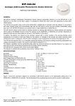
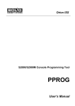
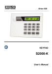
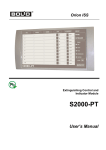
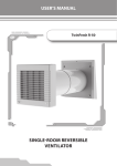
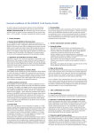
Orion ISS ISO 9001 Uninterrupted Power Supply RIP-12 RS User’s Manual This User’s Manual is intended to help for studying operability principles and maintenance of RIP-12 RS Uninterrupted Power Supply of version 1.02. Please read the instructions completely before connecting, operating, adjusting or maintaining this product. The following terms are used throughout the Manual Zone: a minimal part of the security and safety installation that can be monitored and controlled independently. Depending on the context, the term ‘zone’ can imply an alarm loop, an addressable detector, a hardware component and so on. Partition: A set of zones that can be user controlled as a whole. As a rule, zones fall into partitions depending on their location (e.g., one partition can involve all zones at one individual area) Network Address (Address): – a unique number of the device (from 1 to 127) within the Orion ISS local RS-485 network RIP-12 RS Table of Contents Features and Design.............................................................................................................. 5 Specifications ........................................................................................................................ 9 Operation.............................................................................................................................. 13 Operation Principles ................................................................................................................... 14 Trouble Output Relay.................................................................................................................. 15 RIP-12 RS Indication .................................................................................................................. 16 Data Communications via RS-485 Interface............................................................................... 18 Condition Message Transmission 18 Remote Control via RS-485 interface 20 S2000M Console Remote Requests for RIP-12 RS Conditions 20 S2000M Console Requests for Remote Reading of RIP-12 RS Parameter Values 21 Installation............................................................................................................................ 23 Accessories ................................................................................................................................ 24 Safety Precautions...................................................................................................................... 24 Mounting the Cabinet.................................................................................................................. 25 RIP-12 RS Wiring ....................................................................................................................... 25 RIP-12 RS to RS-485 Interface Line Connection 26 RIP-12 RS Starting Up 27 RIP-12 RS Shut Down ................................................................................................................ 28 Programming ....................................................................................................................... 29 UPROG Configuration Tool Operations...................................................................................... 30 RIP-12 RS Configuration Parameters......................................................................................... 32 RIP-12 RS Network Address Programming................................................................................ 32 AC Condition Message Delay Programming .............................................................................. 33 Trouble Relay Programming....................................................................................................... 33 Maintenance ......................................................................................................................... 35 Troubleshooting .......................................................................................................................... 36 RIP-12 RS Inspection Check-off................................................................................................. 37 Appendix Bolid RIP Uninterrupted Power Supplies and Accessories ............................. 39 3 www.bolid.com Orion ISS www.bolid.com 4 RIP-12 RS Features and Design FEATURES AND DESIGN 5 www.bolid.com Orion ISS RIP-12 RS Uninterrupted Power Supply with the RS-485 communication port (hereinafter referred to as RIP-12 RS) is designed to provide continuous operating power to a group of security and safety electronic equipment that require 12 Volt of DC. RIP-12 RS provides round the clock operation with specified voltage output and automatic monitoring and recharging of sealed backup battery (hereinafter referred to as “battery”). RIP-12 RS also features: ¾ ¾ Extended input voltage range of 150 to 250 Volt AC Monitoring and indication for troubles of mains input voltage, backup battery and battery power charger ¾ ¾ Automatic battery shutoff to prevent battery down Output short-circuit protection with automatic voltage recovering after repair, along with output overvoltage protection ¾ Battery protection against short circuit failures between terminals, output voltage being kept up upon operating from mains power ¾ Temperature compensation for battery power charger within operating temperature range, as well as monitoring for charger output voltage and current to provide optimal battery charging ¾ Monitoring for conditions of the battery and its connection circuits by means of comparison with maximum allowable internal resistances of these circuits www.bolid.com 4 5 3 6 2 7 1 8 6 RIP-12 RS Features and Design RIP-12 RS is equipped with five LED indicators to provide local condition and trouble indication. POWER Indicator (4), CHARGE Indicator (3) and 12V Indicator (5) are intended to display conditions of input mains power, battery power charger and DC output. FAULT Indicator (8) signalizes all kinds of occurring internal troubles, while RS-485 Indicator (6) indicates communication condition between RIP-12 RS and a network controller via RS-485 interface line. RIP-12 RS has a built in sounder to alert personnel of detected faults. The sounder can be deactivated if desired. RIP-12 RS is equipped with RS-485 communication port, through which it can be connected to the Orion system RS-485 local network in order to communicate date with an Orion network controller. The Orion network controller can be either Bolid manufactured S2000М/S2000 ver.1.10+ Fire & Alarm Console or Orion Workstation Software set on a PC. In such a case RIP-12 RS additionally provides: ¾ Centralized remote RIP-12 RS parameter setting from the location of the Orion network controller ¾ ¾ Synchronizing of its internal clock with the clock of the network controller Transmitting the network controller various types of messages when some troubles occur. If a temporary communication loss happens to be during trouble occurring these messages are stored within RIP-12 RS nonvolatile memory (up to 29 messages), and then after RS-485 communications resuming the stored messages are transmitted to the network controller along with actual event data and time in accordance with internal RIP-12 RS clock. ¾ Upon a request of the network controller reading and transmitting of input and output electrical parameters or tamper switch conditions. This allows using RIP-12 RS as an additional source of information for analysis of current system events, as well as a mean for continuous on-line monitoring of mains utility power parameters and quality. ARM S2000 Engineer Package Software, for example, provides on-line displaying of the information being received in the form of scalable diagrams. Moreover, RIP-12 RS is equipped with opto-relay output with galvanic isolation enabling remote transmission of trouble messages without regard to communication conditions between RIP-12 RS and a network controller or network controller inoperability. The operating tactics is variable and user selectable as one of the four available executive programs with the execution time also programmable by a user. RIP-12 RS is housed in a tamper proof steel cabinet that consists of a wall mountable base (2) and key lock (7) protected door (1). RIP-12 RS Uninterrupted Power Supply is suited for indoor applications and must be protected from water, ice, snow as well as mechanical damage. 7 www.bolid.com Orion ISS www.bolid.com 8 RIP-12 RS Specifications SPECIFICATIONS 9 www.bolid.com Orion ISS ¾ RS-485 Communication Port Yes ¾ Visual Trouble Indicators AC Power Battery Charge Condition Fault RS-485 Communication Fault Backup Battery Power ¾ Trouble Relay Commutation Voltage 80 V max Switched Current 100 mA max Resistance for a Closed Relay Circuit 50 Ohm max Open Circuit Leakage Current 1 µA @ 80V ¾ Input Voltage 150 V AC to 250 V AC at 50 Hz ¾ Input Current 0.7 A max at 150 V AC ¾ Power Consumption 110 VA max ¾ AC Fuse 2A ¾ Backup Battery Type 12 V Sealed Lead Acid Rechargeable Battery, 17 Ahr ¾ Low Battery Shutdown Voltage 10.2 ± 0.6 V ¾ Battery Full Charge Time 48 hours max ¾ Battery Space (W×D×H) 181 × 77 × 167 mm ¾ Backup Operating Time at least 4 hours from fully charged battery at 3-A load current and 25°C ¾ Output Voltage 13.6 V DC ± 0.6 V DC at Mains Power On 9.5 V DC to 13.5 V DC at Mains Power Off ¾ Output Voltage Ripple 0.12 V DC peak-to-peak max at rated load current ¾ Output Current Rating 3A www.bolid.com 10 RIP-12 RS ¾ Maximum Load Current Specifications 4 А (short periods of about 10 minutes once per an hour). NOTES: When an output current value has exceeded 3.5 A RIP-12 RS shuts down the battery charger. When an output current value has exceeded 4 A RIP-12 RS shuts down the power outputs. ¾ Operating Temperatures −10 to +40°С ¾ Humidity up to 90% at +25 ºС ¾ Overall Dimensions 255 × 310 × 95 mm ¾ Weight (with a Battery) about 8.5 kg ¾ Average Lifetime 10 years NOTE: Every five years a backup battery must be replaced. ¾ Readiness Period 6 s max 11 www.bolid.com Orion ISS www.bolid.com 12 RIP-12 RS Operation OPERATION 13 www.bolid.com Orion ISS OPERATION PRINCIPLES After powering on, RIP-12 RS checks for backup battery presence and normal RS-485 communications with a network controller. If the battery − Is connected and its voltage exceeds 13.2 V the CHARGE indicator is lit, − Is not properly charged RIP-12 RS charges it, CHARGE LED being out periodically once per 3 seconds, − Is not connected or its output voltage is lower than 7 V CHARGE LED is off, − Is dead and needs to be replaced CHARGE and FAULT LEDs flashes twice per a second, the internal sounder producing pulsed sounds for 10 seconds. If a battery power charger trouble occurs, RIP-12 RS detects its within 15 minutes, indicating this event as described in Table 1 and transmitting the CHARGER FAILED message to a net controller. When operating, RIP-12 RS periodically inspects: − The battery presence (at least every minute) − The battery condition (at least once per 15 minutes) − The charger operability (at least once per 15 minutes) In case of mains power outage, − The backup battery is activated to supply power to the load circuits − The interrupted sound signal goes off warning about battery discharge − The POWER LED is off − The 12 V LED is lit − Once a pre-programmed delay (see p.33) has elapsed the RIP-12 RS transmits the AC POWER FAILED message to the net controller If the battery output voltage drops to 11 V, the sounder begins to play interrupted sounds more frequently and the BATTERY FAILED message is transmitted to the Orion network controller. Immediate actions must be taken to provide mains power voltage. If the battery output voltage drops to 10 V, the battery is shut down to prevent its deep discharge. In this case − The 12 V LED is off − The sound alarms go off continuously for the first two hours and then once per 10 s www.bolid.com 14 RIP-12 RS − Operation RIP-12 RS transmits the POWER OFF message to the Orion network controller NOTE: RIP-12 RS sound alarms can be disabled by means of special pressing on the RIP-12 RS tamper switch (see RIP-12 RS Indication Section, p.16). The repeated pressing on the tamper switch will enable RIP-12 RS sound alarms. If an inadmissible load circuit over-current or short load circuit failure occurs, RIP-12 RS − Applies a DC voltage to its outputs for a short time period every 10 seconds to detect current conditions − The FAULT LED flashes twice per a second − The RIP-12 RS sounder plays interrupted alarm sounds Within 15 seconds after the malfunction has been repaired the DC output proper operation is resumed automatically. TROUBLE OUTPUT RELAY RIP-12 RS has a built-in ‘trouble output’ relay which is operated by one of several trouble conditions, including RS-485 communication fault, RIP-12 RS enclosure tampering, both mains and backup input power troubles, DC power and charger faults, as well as DC output overcurrent. This relay is intended to transmit troubles remotely, for example, to a central station, without regard to RS-485 communication condition. The actual trouble events that will be transmitted by means of the relay can be selected by user from pre-determined list of events. The relay can be programmed to operate in accordance with one of the four available executive programs defining behavior of the relay upon trouble event occurring, among them Switch OFF (by default) The relay is switched off when a selected trouble condition exists, being switched on otherwise Switch ON The relay is switched on when a selected trouble condition exists, being switched off otherwise Switch ON for a Time When a selected trouble has occurred the relay is switched on for a specified time, then or otherwise the relay is switched off Switch OFF for a Time When a selected trouble has occurred the relay is switched off for a specified time, then or otherwise the relay is switched on The execution time expressed by the Time parameter in two last executive programs is also programmable within the range of 0 to 255 seconds, the factory value being 255 s. 15 www.bolid.com Orion ISS RIP-12 RS INDICATION RIP-12 RS indicates its operation conditions and troubles by means of five LEDs and internal sounder as described in Table 1. Following is the list of notations used in Table 1. + Switched ON ─ Switched OFF +/─ 1 Hz Switches on and off alternately every second +/─ 2 Hz Switches on and off alternately twice per a second +/─ 4 Hz Switches on and off alternately four times per a second OFF / 3s Turns off every 3 seconds ON / 0.4s Turns on every 0.4 seconds ON / 0.8s Turns on every 0.8 seconds ON / 5s Turns on every 5 seconds ON / 10s Turns on every 10 seconds The sound signaling of RIP-12 RS can be hardware disabled if necessary. This is doing by making short-short-short-long pressing on RIP-12 RS tamper switch on the top left side of the enclosure just under the RIP-12 RS door. The term ‘long’ means more than 1.0 s, while the term ‘short’ means less than 0.5 s. The pauses between pressings must not exceed 0.5 s. The repeated pressing will enable the sound signaling mode again. www.bolid.com 16 RIP-12 RS Operation Table 1. RIP-12 RS Light and Sound Indication Indicator lights RIP-12 RS Condition POWER CHARGE green green FAULT yellow RS-485 green 12 V green Internal Sounder Mains utility power is starting up, the battery is not connected + ─ ─ +1 + ON / 0.4 s 3 times Mains utility power is supplied to the RIP-12 RS and the battery is not charged + OFF / 3s ─ +1 + ─ Mains utility power is supplied to the RIP-12 RS and the battery is charged + + ─ +1 + ─ DC output overcurrent (a battery is available) + + +/─ 2 Hz +1 ON / 10s ON / 0.8s Mains power is disabled, the battery voltage exceeding 11 V ─ + ─ +1 + ON / 5 s Mains power is disabled, the battery voltage dropping below 11 V ─ + ─ +1 + ON / 0.4 s Mains power is shut off and battery voltage is lower than 10.2 V, within first two hours ─ +/─ 1 Hz ─ +1 ─ + Mains power is shut off and battery voltage is lower than 10.2 V, after two hours expiring ─ +/─ 1 Hz ─ ─ ─ ON / 10 s Mains power voltage is lower than 150 V or higher than 250 V (the battery is available) +/─ 1 Hz + +/─ 1 Hz +1 + See Note 2 Dead battery (must be replaced) + +/─ 2 Hz +/─ 2 Hz +1 + 5 beeps Battery charger fault + +/─ 4 Hz +/─ 4 Hz +1 + ON / 0.8s Output overvoltage +/─ 1 Hz +/─ 1 Hz +/─ 1 Hz +/─ 1 Hz ─ ─ NOTES: 1. If RIP-12 RS is connected to a network controller communicating data with it via RS-485 interface. If RS-485 data communications have been lost for more than 30 s the RS-485 LED begin flashing once per a second, while if RIP-12 RS is disconnected from the network controller the RS-485 LED is off. 2. Upon mains power troubles the behavior of the internal sounder depends on backup battery voltage and is similar to its behavior in case of mains power outage – see four previous conditions. 17 www.bolid.com Orion ISS DATA COMMUNICATIONS VIA RS-485 INTERFACE The RIP-12 RS Power Supply connected to an Orion network controller via RS-485 interface transmits condition and trouble messages to the net controller, enabling remote indicating of various troubles. These messages can be redirected by the network controller to other devices of the Orion system, such as indicator modules (this possibility is reserved for future use) or relay modules, for centralized remote both indication and notification as well as executive program’s activation. Moreover, S2000/S2000M console and a number of software tools are capable of sending remote requests to RIP-12 RS devices asking them for their operation conditions and for their electrical parameters values. These features enable using RIP-12 RS devices as a mean of continuous on-line monitoring for electric power parameters and quality. Condition Message Transmission If connected RIP-12 RS automatically transmits a network controller a number of its condition messages. These messages are displayed by the network controller together with an indication of the RIP-12 RS network address and a logical zone or ‘loop’ number which corresponds to a separate hardware zone of RIP-12 RS (see below). If the network controller is properly adjusted the messages are displayed with partition names instead of network addresses. The message type depends on zone (‘Loop’) number as follows. ‘Loop’ # 0 – messages from the RIP-12 RS itself (the number 0 is not displayed) DEVICE RESTART RIP-12 RS power has just been turned up TAMPER ALARM RIP-12 RS enclosure has just been opened TAMPER RESTORE RIP-12 RS enclosure has just been closed ‘Loop # 1 – DC output voltage zone messages POWER FAILED RIP-12 RS fails to supply power in accordance with its specification when connected to the live AC line POWER RESTORE RIP-12 RS has just begun to supply power in accordance with its specification after its failure POWER OFF RIP-12 RS output voltage has shut off because AC power and backup battery have failed POWER ON www.bolid.com RIP-12 RS has just begun to operate normally after failure 18 RIP-12 RS Operation ‘Loop’ # 2 – DC output current zone messages OVERCURRENT RIP-12 RS output current has exceeded 4 A CURRENT RESTORE RIP-12 RS output current has just dropped below 3.5 А ‘Loop’ # 3 – battery zone messages BATTERY FAILED The battery voltage is below 7 V, or there is no battery connected, or the internal battery resistance is less than the admissible value and the battery must be replaced BATTERY RESTORE The battery voltage has exceeded 10 V so the battery can be charged ‘Loop’ # 4 – power charger zone messages CHARGER FAILED The battery power charger doesn’t provide specified voltage and current values to charge a battery CHARGER RESTORE The battery power charger operability has just been restored ‘Loop’ # 5 – AC power zone messages AC POWER FAILED Input AC voltage is less than 150 V or more than 250 V AC POWER RESTORE Input AC voltage has just been returned to a normal value (between 150 V and 250 V) NOTES 1. RIP-12 RS provides buffering of events that should be transmitted to a network controller. If a temporary communication loss happens to be during generating of a message then the messages are stored within RIP-12 RS nonvolatile memory (up to 29 last messages can be stored at once). Then, after RS-485 communications resuming, the stored messages are transmitted to the network controller along with actual event data and time in accordance with internal RIP-12 RS clock. 2. AC POWER FAILED and AC POWER RESTORE messages are transmitted to an Orion network controller after AC POWER FAILED Message Delay and AC POWER RESTORE Message Delay seconds correspondently. By default these values are equal to 3 seconds each and can be incremented up to 255 seconds upon RIP-12 RS configuring by means of UPROG Configuration Tool (see AC Condition Message Delay Programming Section of this Manual). 19 www.bolid.com Orion ISS Remote Control via RS-485 interface RIP-12 RS responds to commands received via RS-485 interface line from a network controller or supervisory Orion application software, such as S2000(M) console, ARM Orion Pro, ARM S2000, or UPROG Configuration Tool. These commands include: ¾ ¾ ¾ RIP-12 RS with a net controller clock synchronization RIP-12 RS parameter values remote reading and writing Remote requests for the conditions of RIP-12 RS power inputs and outputs as well as battery charger and tamper switch conditions. ¾ Remote requests for reading input and output electrical parameters for continuous on-line monitoring of electrical power parameters and quality. The specific list of enabled commands depends on the type of the network controller or the type and version software being in use see the corresponding Manual for the description of remote requests mentioned above. The remote parameter setting is implemented by means of UPROG Configuration Tool which will be described in the Programming Section. Following is the description of remote requests for RIP-12 RS condition and parameter reading sent by a S2000M console. S2000M Console Remote Requests for RIP-12 RS Conditions RIP-12 RS responds to the remote condition requests from a S2000M console by transmitting measured parameters of various zones which are defines as follows: 0 – Tamper switch zone 1 – DC output voltage zone 2 – DC output current zone 3 – Battery output voltage zone 4 – Battery power charger zone 5 – AC input voltage zone To request for a RIP-12 RS condition from the S2000M console: ENTER CODE:_ Enter your PIN-code v 5 REQUEST INFO Select REQUEST INFO command by 3 or 4 console button and press ENTER, or use 050 console button as the hot key. v 51 ZONE STATE Select ZONE STATE command by 3 or 4 console button and press ENTER, or use 010 console button as the hot key. ADDRESS:_ Enter RIP-12 RS network address or select the valid value by 3 or 4 console button and press ENTER. www.bolid.com 20 RIP-12 RS ENTER LOOP#:_ Operation Enter the zone number (or ‘LOOP#’) in accordance with the parameter to be requested (see above) or select the proper value by 3 or 4 console button and press ENTER. The responses from RS-RIP zone conditions are treated similarly RIP-12 RS condition messages described in the Condition Message Transmission Section of this Manual. S2000M Console Requests for Remote Reading of RIP-12 RS Parameter Values RIP-12 RS provides reading and transmitting the S2000M console the values of such electrical parameters as: – Mains utility voltage within the range of 150 to 260 V AC – Battery output voltage within the range of 8 to 14.5 V DC – DC output voltage within the range of 8 to 14.5 V DC – DC output current (load current) within the range of 0.1 to 4 A NOTE: All these reading are estimations rather than precise values. Use certified instruments to measure electrical parameters more accurately. To request for reading RIP-12 RS electrical parameters from the S2000M console: ENTER CODE:_ Enter your PIN-code v 5 REQUEST INFO Select REQUEST INFO command by 3 or 4 console button and press ENTER, or use 050 console button as the hot key. v 51 ZONE ADC Select ZONE ADC command by 3 or 4 console button and press ENTER, or use 020 console button as the hot key. ADDRESS:_ Enter RIP-12 RS network address or select the valid value by 3 or 4 console button and press ENTER. ENTER LOOP#:_ Enter the zone number (or ‘LOOP#’) in accordance with the value to be requested (#0 is disabled for remote reading) or select the proper value by 3 or 4 console button and press ENTER. The responses from RS-RIP can be as follows: For zone 1 – Vout = 8…14,5V, or Vout = 0 meaning that the DC output is shut down For zone 2 – Iout = 0,1…4A, or Iout = 0 meaning that the load current is more than 4 A or there is no load For zone 3 – Vbat = 8…14,5V, or Vbat = 0 meaning that there is no battery For zone 4 – CG_NORM / CG_FAIL (is the battery power charger working or not) For zone 5 – Vin =150…260V, Vin < 150V, or Vin > 260V 21 www.bolid.com Orion ISS www.bolid.com 22 RIP-12 RS Installation INSTALLATION 23 www.bolid.com Orion ISS ACCESSORIES Find the following when unpacking the RIP-12 RS: ¾ RIP-12 RS Uninterrupted Power Supply housed in a grey steel, powder-coated Cabinet. The Cabinet consists of a Base and a key lockable Door ¾ ¾ This User’s Manual RIP-12 RS Accessories (see Figure 1), among them 1 1. AC Fuse 2. Two Plastic Bushings 3. Three Wall Plugs 2 4. Three Woodscrews 3 5. Two Mechanical Lock Keys 5 4 Figure 1. RIP-12 RS Accessories Please take into account that RIP-12 RS comes without a backup battery which should be purchased separately (see Section Specifications). SAFETY PRECAUTIONS The RIP-12 RS Power Supply’s sources of potential hazard are current carrying circuits which are covered by a yellow protective housing to prevent electrical shock damage. NEVER REMOVE THE YELLOW PROTECTIVE HOUSING FROM RIP-12 RS BASE DO ALWAYS SHUT OFF MAINS UTILITY POWER BEFORE MOUNTING, WIRING OR MAINTAINING OF RIP-12 RS BE SURE THE RIP-12 RS IS PROPERLY GROUNDED BE SURE THE AC FUSE IS OPERABLE AND ITS AMPERAGE IS VALID IN ACCORDANCE WITH THE SPECIFICATION IN THIS MANUAL DO ALWAYS SHUT OFF MAINS POWER AND REMOVE AC FUSE WHEN SETTING OR REPLACING THE BACKUP BATTERY www.bolid.com 24 RIP-12 RS Installation MOUNTING THE CABINET 310 150 83 190 127 255 Figure 2. RIP-12 RS Cabinet Drilling Pattern RIP-12 RS power supply is mounted at the places protected from atmospheric fallout, mechanical damage and unauthorized access. S2000-R overall and mounting dimensions are shown in Figure 2. Attach the RIP-12 RS cabinet to a wall or other constructions surface by means of three screws provided. The cabinet is hinged and pushed to put on two top screws, then it is fixed by tightening central screw. RIP-12 RS WIRING The top view of the RIP-12 RS base is shown in Figure 3. Mounting and wiring of electrical wires are implemented in accordance with the drawing of electrical connections shown in Figure 4. The installation and wiring must be performed by a competent engineer. Route all cables through the knock out holes on the right hand side of the enclosure base protecting them by means of plastic bushings provided. CAUTION! Remove the Fuse Holder from the Fuse Terminal Block (see Figure 3) before starting to wire in order to avoid premature connecting of mains utility power to the RIP-12 RS PCB CAUTION! Pay special attention connecting Line and Neutral wires and correctly CAUTION! Never use RIP-12 RS if it is not grounded properly 25 www.bolid.com Orion ISS EOL (Jumper) Terminals RS-485 Terminals Relay Terminals Output Terminal Blocks Negative Battery Terminal Lead Positive Battery Terminal Lead Fuse Terminal Block L N Fuse Holder Figure 3. RIP-12 RS Base Top View RIP-12 RS to RS-485 Interface Line Connection To connect RIP-12 RS to a net controller via RS-485 interface line couple B and A contacts of ХТ2 terminal block (see Figure 4) with B and A wires of RS-485 line respectively. If RIP-12 RS is not the first or the last device in the RS-485 interface line remove EOL Jumper from XP1 Terminals located close to B and A contacts of ХТ2 (see Figure 3). If the network controller is supplied by other power supply, not by the RIP-12 RS, couple 0 V circuits of the network controller and the RIP-12 RS. In order to communicate with the network controller the RIP-12 RS power supply shall be assigned with a unique network address (see Section RIP-12 RS Network Address Programming). The default factory address value of any RIP-12 RS is 127. www.bolid.com 26 RIP-12 RS Installation RS-485 Network Trouble Relay (80 V, 100 mA max) DC Output 13.6 V, 3 А Disconnect X3 from X4 for immediate shut-off of the battery Fuse Terminal Block blue red Battery 12 V, 17 Аhr N, Neutral Earth L, Line 220 V 50 Hz Figure 4. Drawing of RIP-12 RS Electrical Connections RIP-12 RS Starting Up RIP-12 RS electrical wiring and turning on is implemented as follows (see Figure 4). 1. Connect protective ground to the terminal 2 of the Fuse Terminal Block. 2. Remove the F1 Fuse Holder from the Fuse Terminal Block, then couple RIP-12 RS terminal 1 with the Live wire and RIP-12 RS terminal 3 with the Neutral wire. Do not switch the mains ON. 3. Connect load circuits to the DC outputs (terminals 1 to 6 of the XT1 terminal blocks). 4. Connect the backup battery coupling the blue battery lead with the negative battery contact and the red battery lead with the positive battery contact. In order to disconnect the battery immediately there is the removable connection blocks X3-X4 within the red wire. 5. Insert F1 Fuse to the Fuse Holder and put the Fuse Holder to the Fuse Housing at the Fuse Terminal Block. 6. Turn mains utility power on. WARNING! To ensure specified features the backup battery must be always connected and operable. If during RIP-12 RS operating the battery is connected but inoperable and the RIP-12 RS indicates a battery fault this battery must be replaced immediately. In any case replace a battery every 5 years. 27 www.bolid.com Orion ISS RIP-12 RS SHUT DOWN Shut off RIP-12 RS by doing the following. 1. Shut off mains utility power. 2. Remove the AC Fuse Holder from the Fuse Terminal Block. 3. Disconnect the backup battery. 4. Disconnect load circuits. www.bolid.com 28 RIP-12 RS Programming PROGRAMMING 29 www.bolid.com Orion ISS If RIP-12 RS is connected to an Orion network controller via RS-485 interface line it is necessary to set some its configuration parameters, first of all its network address (all Orion system devices are shipped with factory set address values of 127). To program RIP-12 RS connect it to a personal computer (PC) via one of such RS-485/RS-232 interface converters as S2000-PI, PI-GR or S2000(М) in the specified mode. The Orion devices’ configuration tool UPROG Configuration Tool version of 4.0.0.914 and above must be setup on the PC. The network address can be assigned to RIP-12 RS or changed also by means of S2000(M) console tools in accordance with S2000(M) User’s Manual. The most up-to-date version of UPROG.EXE can be found on the web site of the Bolid Company at the address www.bolid.com, in DOWNLOAD section. In some cases in order to implement centralized remote trouble indication from all system power supplies it can be necessary to change settings of a network controller database. These changes are made by means of PPROG Programming Tool (if a S2000/S2000M console plays the role of the network controller) of Orion Database Administrator (if Orion Workstation Software controls the system). An explicit description of the adjusting procedure can be found in a network controller user’s manual. UPROG CONFIGURATION TOOL OPERATIONS Program the RIP-12 RS by doing the following. 1. Connect the RIP-12 RS to the PC via an interface converter and run UPROG Configuration Tool. 2. Select Device→Read Device Configuration menu command (or use Ctrl-F3 key, or select toolbar icon). The Search Device Window will appear and you will be prompted for the number of the COM port (Serial port) of the PC which the RIP-12 is connected to. Enter the valid COM port number and press the Search button. 3. When a list of found devices with their addresses and version numbers will be shown select the required RIP-12 RS and press the Select button. 4. The window displaying current RIP-12 RS settings will be opened (see Figure 5). You can program the device as necessary. You can also program the device by loading device configuration from a file of internal UPROG format by means of File→Load Configuration File command (or pressing F3, or selecting toolbar icon). Moreover, you can create a new configuration by means of File→New configuration command (or pressing Ctrl-N key, or selecting www.bolid.com toolbar icon). 30 RIP-12 RS Programming Figure 5. RIP-12 RS Programming Window The newly created or changed configuration can be: Written to the memory of the current , «Device»→«Write Configuration To This Device» device Written to the memory of any other «Device»→« Write Configuration To Another Device…» similar device with specified address connected to the computer Written to a file in UPROG internal , <F2>, «File»→«Save Configuration To File» format with .cnu extension Written as a text to a MS Word file , «File»→«Export Configuration To MS Word» 31 www.bolid.com Orion ISS RIP-12 RS CONFIGURATION PARAMETERS The set of parameters that are programmed by means of UPROG Configuration Tool and stored in RIP-12 RS non-volatile memory is as follows. Description Range Factory Value Network Address The unique number of RIP12 RS within address space of a network controller 1…127 127 AC POWER FAILED Message Delay The time period to delay this message transmission after mains power voltage has dropped below 150 V or exceeded 250 V 3…255 s 3s AC POWER RESTORE Message Delay The time period to delay this message transmission after mains power voltage has returned to be within 150 V to 250 V range 3…255 s 3s Parameter Trouble Relay Parameters Executive Program Describes the type of relay behavior upon a trouble listed below having occurred. A program can be implemented only if either mains or backup power is supplied Relay Active Time The ‘Time’ value in third and fourth executive programs (see above) Relay Activation Events The list of trouble events which can activate the relay triggering remote trouble indication Switch OFF Switch ON Switch ON for a Time Switch OFF for a Time (see below) Switch OFF 0…255 s 255 s All except RS-485 com.fault RS-485 communication fault Output overcurrent DC or charger fault Battery trouble/missing AC voltage is out of 150-250V RIP-12 RS tampering + + + + + + RIP-12 RS NETWORK ADDRESS PROGRAMMING To assign a unique RS-485 network address to RIP-12 RS select Device→Change Device Address menu command and specify the required address value in the address field of the window having been opened. The address value can range from 1 to 127, but it must not match with any address of another Orion system device connected to the same network controller. www.bolid.com 32 RIP-12 RS Programming RIP-12 RS devices provide hard reset of the network address to a factory value of 127. For doing this, open the RIP-12 RS door and sequently make long-long-long-short pressing on the tamper switch. The term ‘long’ means more than 1.0 s, while the term ‘short’ means less than 0.5 s. The pauses between pressings must not exceed 0.5 s. AC CONDITION MESSAGE DELAY PROGRAMMING When AC voltage is lower than 150 V or exceeds 250 V, RIP-12 RS starts to be supplied by the backup battery, transmitting network controller an AC POWER FAILED message. By default this message is transmitted to the network controller after 3 seconds since switching from mains power to backup power supply. Similarly, within some seconds (3 by default) after AC power having been returned an AC POWER RESTORE message is transmitted to the network controller. These time delays are defined by the AC POWER FAILED Message Delay and AC POWER FAILED Message Delay correspondently and can be increased up to 255 seconds. If necessary, increment the default values or insert the desired value in the specified fields as shown in Figure 6. Figure 6. Programming AC Condition Message Delays TROUBLE RELAY PROGRAMMING RIP-12 RS is equipped with its own trouble relay to notify the system when a trouble condition has occurred. This relay can be programmed to operate in accordance with one of the four available tactics (executive programs), which describes the behavior of the relay upon trouble conditions, among them: Switch OFF (by default) The relay is switched off when a selected trouble condition exists, being switched on otherwise Switch ON The relay is switched on when a selected trouble condition exists, being switched off otherwise Switch ON for a Time When a selected trouble has occurred the relay is switched on for a specified time, then or otherwise the relay is switched off Switch OFF for a Time When a selected trouble has occurred the relay is switched off for a specified time, then or otherwise the relay is switched on 33 www.bolid.com Orion ISS The Time parameter in two last executive programs is also programmable in the interval from 0 to 255 seconds, the factory value being 255s. Figure 7. Programming the Trouble Relay In order to program the trouble relay, select the suitable Executive Program from the list (see Figure 7) and define Relay Active Time value, if necessary. Note than the specified time will be automatically increased by 15 seconds for the ‘Enclosure tampering’ event. It means that if the relay must be activated for Relay Active Time seconds and if the enclosure tampering is selected to activate the relay then after enclosure tampering having been detected the relay will be activated in accordance with the executive program specified for Relay Active Time + 15 seconds. Finally, specify trouble conditions that will be indicated by relay activation. To do this, click at right field on the line containing that event which should cause the relay switching, and this event will be marked by ‘+’ sign. You can select all these events or specify only those you require in. Note that all events are selected separately, except of the first line which enables selecting all troubles of RIP-12 RS at once by a single click. To remove an event from the list of selected ones click on the respective ‘+’ sign repeatedly. www.bolid.com 34 RIP-12 RS Maintenance MAINTENANCE 35 www.bolid.com Orion ISS TROUBLESHOOTING V RIP-12 RS is not turning on when connected to the AC line Check for AC line good condition V RIP-12 RS is not turning on when connected to the backup battery Check for battery output voltage. Charge or replace the battery if the measured voltage is lower than 10 V V RIP-12 RS transmits BATTERY FAILED message Check for AC fuse condition and replace the fuse if necessary Check battery age and replace the battery if it is old or dead Check condition of the battery leads for contamination or loose connection. Clean the leads and re-tighten hardware V RIP-12 RS communications are lost Check RS-485 line connections and cable condition Check if RS-485 cable is connected properly. If A line is connected to the B terminal of the RIP-12 RS PCB or B line is connected to the A terminal (see Figure 3) correct improper polarity. Inspect XP1 terminals on the RIP-12 RS PCB. If RIP-12 RS is the first or last device brought to RS-485 interface line then the jumper must be plugged in, otherwise it must be removed If the network controller is connected to another power supply rather than to RIP-12 RS, check if the 0 V circuits of the RIP-12 RS and the network controller are coupled www.bolid.com 36 RIP-12 RS Maintenance RIP-12 RS INSPECTION CHECK-OFF To make sure the RIP-12 RS keeps reliably and proper operation condition, inspect it at least annually. The RIP-12 RS must be tested under the following ambient conditions: − − − Temperature 25 C Relative humidity 45 ÷ 80 % Atmospheric pressure 630 ÷ 800 mm Hg In order to inspect RIP-12 RS: ¾ ¾ ¾ Check RIP-12 RS for contaminations and mechanical damage Verify security of RIP-12 RS mounting, connecting wire conditions and external connections Inspect RIP-12 operability for proper output voltage in accordance with RIP-12 RS specifications (see Specifications Section of this Manual) and for proper indication (see RIP-12 RS Indication Section of this Manual). CAUTION! Shut off mains utility power before disconnecting and connecting wires while condition inspecting 37 www.bolid.com Orion ISS www.bolid.com 38 RIP-12 RS Appendix Bolid RIP Uninterrupted Power Supplies and Accessories 39 www.bolid.com Orion ISS Bolid Company manufactures a wide range of uninterrupted power supplies designed to supply voltage to a group of Orion detectors or other electronic devices. Their specifications are shown in the table below. CLASSIC UNINTERRUPTED POWER SUPPLIES 12 V Output Voltage Output Current, Model Backup Battery Overall Dimensions rated/max for 2 min RIP-12-1А-1.2Аhr 1 A / 1.5 A 1.2 Ahr 120×220×65 mm RIP-12-1А-1.2Аhr Protection 1 A / 1.5 A 1.2 Ahr 120×220×65 mm RIP-12-1А-7Аhr Protection 1 A / 1.5 A 7 Ahr 200×220×80 mm 1A/2A 7 Ahr 200×220×80 mm 2×4 Ahr 200×220×80 mm RIP-12 rev.03 24 V Output Voltage RIP-24-0.8А-4Аhr Protection 0.8 A / 1.5 A INTELLIGENT UNINTERRUPTED POWER SUPPLIES 12 V Output Voltage RIP-12 rev.01 3A/4A 17 Ahr 255×310×85 mm RIP-12 rev.04 2A/5A 7 Ahr 255×310×85 mm RIP-12 rev.02 2A/5A 7 Ahr 200×220×80 mm RIP-12 rev.05 8 A / 10 A 7 Ahr 255×310×85 mm 24 V Output Voltage RIP-24 rev.01 3A/6A 2×7 Ahr 340×270×95 mm RIP-24 rev.02 1A/3A 2×7 Ahr 340×270×95 mm RIP-24 rev.04 1A/3A 2×4 Ahr 200×220×80 mm www.bolid.com 40 RIP-12 RS Moreover, Bolid Company provides a number of RIP accessories. In order to provide input AC line over-voltage and surge protection in case of natural or technological disasters we recommend using of our BZS AC Line Protection Module. For some RIP models without RS-485 communication port MKS RIP Monitoring Module provides light indications for three types of faults and transmits trouble signals to a net controller. It is equipped with three trouble output relays to give warnings in cases of input and output voltage troubles and backup battery voltage troubles. In order to distribute RIP power to supply several electronic devices BZK DC Power Distribution Modules are used which convert a single DC input into six or eight individually-fused and noise suppressed outputs, each equipped with its own power LED indicator. Finally, Bolid manufactures special over-voltage and improper polarity protected Boxes to contain two extra batteries, and some models of MP 24/12 V DC to DC Converters which supply power from higher voltage sources to electronic devices that require 12 Volt. BOLID RIP ACCESSORIES 12/24V ~220V 12/24V ~220V BZS AC Line Over-voltage and Surge Protection Module BZK DC Power Distribution Module 24V 12V MP 24/12 V DC to DC Voltage Converters Box trouble outputs MKS RIP Monitoring Module 41 www.bolid.com Orion ISS www.bolid.com 42 BOLID ONE YEAR LIMITED WARRANTY Bolid Company and its divisions and subsidiaries («Seller»), 4 Pionerskaya Str., Korolev 141070, Moscow Region, Russia warrants its security equipment (the «product») to be free from defects in materials and workmanship for one year from date of original purchase, under normal use and service. Seller’s obligation is limited to repairing or replacing, at its option, free of charge for parts or labor, any product proven to be defective in materials or workmanship under normal use and service. Seller is not responsible for results where the product is used improperly, where it is used for any application it is not intended for, used under unacceptable environmental conditions and mishandled or stored under improperly. Seller shall have no obligation under this warranty or otherwise if the product is altered or improperly repaired or serviced by anyone other than the Seller. In case of defect, contact the security professional who installed and maintains your security equipment or the Seller for product repair. This one year Limited Warranty is in lieu of all other express warranties, obligations or liabilities. THERE ARE NO EXPRESS WARRANTIES, WHICH EXTEND BEYOND THE FACE HEREOF. ANY IMPLIED WARRANTIES, OBLIGATIONS OR LIABILITIES MADE BY SELLER IN CONNECTION WITH THIS PRODUCT, INCLUDING ANY IMPLIED WARRANTY OF MERCHANTABILITY, OR FITNESS FOR A PARTICULAR PURPOSE OR OTHERWISE, ARE LIMITED IN DURATION TO A PERIOD OF ONE YEAR FROM THE DATE OF ORIGINAL PURCHASE. ANY ACTION FOR BREACH OF ANY WARRANTY, INCLUDING BUT NOT LIMITED TO ANY IMPLIED WARRANTY OF MERCHANTABILITY, MUST BE BROUGHT WITHIN 12 MONTHS FROM DATE OF ORIGINAL PURCHASE. IN NO CASE SHALL SELLER BE LIABLE TO ANYONE FOR ANY CONSEQUENTIAL OR INCIDENTAL DAMAGES FOR BREACH OF THIS OR ANY OTHER WARRANTY, EXPRESS OR IMPLIED, OR UPON ANY OTHER BASIS OF LIABILITY WHATSOEVER, EVEN IF THE LOSS OR DAMAGE IS CAUSED BY THE SELLER’S OWN NEGLIGENCE OR FAULT. Some countries do not allow limitation on how long an implied warranty lasts or the exclusion or limitation of incidental or consequential damages, so the above limitation or exclusion may not apply to you. Seller does not represent that the product may not be compromised or circumvented; that the product will prevent any personal injury or property loss by burglary, robbery, fire or otherwise; or that the product will in all cases provide adequate warning or protection. Buyer understands that a properly installed and maintained alarm may only reduce the risk of a burglary, robbery, fire or other events occurring without providing an alarm, but it is not insurance or guarantee that such will not occur or that there will be no personal injury or property loss as a result. CONSEQUENTLY, SELLER SHALL HAVE NO LIABILITY FOR ANY PERSONAL INJURY, PROPERTY DAMAGE OR OTHER LOSS BASED ON A CLAIM THE PRODUCT FAILED TO GIVE WARNING. HOWEVER, IF SELLER IS HELD LIABLE, WHETHER DIRECTLY OR INDIRECTLY, FOR ANY LOSS OR DAMAGE ARISING UNDER THIS LIMITED WARRANTY OR OTHERWISE, REGARDLESS OF CAUSE OR ORIGIN, SELLER’S MAXIMUM LIABILITY SHALL NOT IN ANY CASE EXCEED THE PURCHASE PRICE OF THE PRODUCT, WHICH SHALL BE THE COMPLETE AND EXCLUSIVE REMEDY AGAINST SELLER. This warranty gives you specific legal rights, and you may also have other rights which vary from country to country. No increase or alteration, written or verbal, to this warranty is authorized. 4 Pionerskaya Str., Korolev 141070, Moscow Region, Russia Phone/fax: +7 495 513-32-35 Email: [email protected] www.bolid.com