1
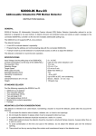
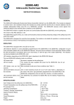
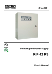
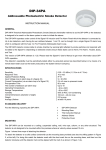
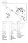
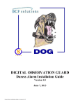
RESETTABLE MANUAL CALL POINT
IPR 513-3M
INSTRUCTION MANUAL
1 TECHNICAL DATA
1.1
General
IPR 513-3M Resettable Manual Call Point (hereinafter referred to as the call point or the IPR 513-3M) is designed to be used in fire
alarm systems and fire extinguishing installations to manually activate fire alarms or manually release the agent discharge.
The IPR 513-3M is to be powered through an alarm loop of such CIE as S2000-4, Signal-20P, S2000-ASPT, Signal-20, SignalVKP, Signal-VK-4P, Signal-VK-4 rev.05, PPK-2, Signal-42, USPP-01L, Signal-10 fire and intrusion alarm panel or similar
providing a voltage up to 30 V within the alarm loop and limiting the current in the loop up to the level of 25 mA.
The hinged transparent protective cover of the IPR 513-3M can be sealed with an intact control seal.
The manual call point is intended for round-the-clock operation.
1.2
1)
2)
3)
4)
5)
6)
7)
8)
9)
Specifications
1.3
Commuted Voltage
Commuted Current
Current Consumed in Quiescent Mode
Ingress Protection Rating
Operating Temperatures
Transportation / Storage Temperatures
Overall Dimensions
Weight
Average Lifetime
- 30 V max
- 25 mA max
- 50 uA max
- IP41
- Minus 30°C to +55°C
- Minus 30°C to +55°C
- 95 mm × 91 mm × 33 mm
- 0.15 kg max
– 10 years
Standard Delivery
For an individual delivery:
– IPR 513-3M
– Instruction Manual
– Special Reset Key
– Woodscrew
– Wall Plug 8×30
– Package
-
1 pc.;
1 pc.;
1 pc.;
2 pcs.;
2 pcs.;
1 pc.
For a group delivery:
– IPR 513-3M
– Instruction Manual
– Special Reset Key
– Woodscrew
– Wall Plug 8×30
– Package
– Group Package
-
10 pcs.;
1 pc.;
10 шт.;
20 шт.;
20 шт.;
10 шт.;
1 pc.
2 OPERATION INSTRUCTIONS
2.1
Wiring
Figure 1 shows a typical connection diagram.
–
4
1
+
+
+
-
-
+
2
+
-
-
3
1 – A CIE,
2, 3 – IPR 513-3M manual call points,
4 – A termination element (resistor, diode, etc.)
Figure 1
The quiescent mode of the IPR 513-3M is indicated by single flashing of its LED once per 4
seconds.
When the manual call point is activated, its LED starts showing solid lighting confirming
that the CIE has received the signal from the IPR 513-3M. In this process the IPR 513-3M
decreases its internal resistance down to 500 Ohm max.
Figure 2 shows the view of the call point (without the protective flip cover):
1 – The hole to insert Reset Key to reinstate the activated call point;
2 – The holes to insert Reset Key to release the front panel of the call point;
3 – Reset Key to reset activated IPR 513-3M / to release its front panel;
4 – The place to apply an intact control seal.
Figure 2
2.2
Mounting
The IPR 513-3M is to be mounted using the two screws provided to a flat vertical surface in accordance with your applicable local
standards, codes, regulations, and ordinances.
The wires which pass under the IPR 513-3M should not be clamped by the IPR 513-3M case.
Before mounting we recommend you to test operability of the manual call point. Before testing, please disconnect executive outputs
of all system devices and modules that can release an extinguishing agent or activate light and sound alarms. Notify the proper
authorities that the system is undergoing maintenance.
To test the IPR 513-3M, connect it to the CIE in accordance with Figure 1 and the instructions from the CIE User’s Manual. Then,
power up the CIE and activate the IPR 513-3M by pressing the black marking. The IPR 513-3M shall enter the Fire Alarm mode, the
call point LED showing solid light. Finally, reset the call point to the quiescent mode by inserting the Special Key. Ensure the call
point LED flashes once per 4 s.
Disconnect the IPR 513-3M from the CIE. Attach the IPR 513-3M to a selected location and connect it into the alarm loop of the
CIE. Repeat testing operability of the IPR 513-3M as described above at least three times. After testing, ensure the IPR 513-3M is
ready for normal operation. Then restore operability of all the system components disconnected before testing and notify the proper
authorities that the system is back in operation.
Test the operability of the manual call point at least once per three months..
All the equipment used in testing must be known functioning.
ZAO NVP Bolid, 4 Pionerskaya Str., Korolev 141070, Moscow Region, Russia
Phone/fax: +7 495 775-7155
Email: [email protected]
Technical Support: [email protected]
http://bolid.ru