1
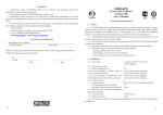
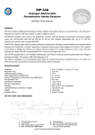
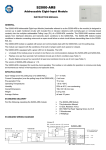
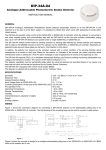
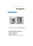
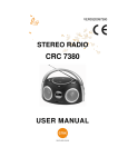
S2000-IK Rev.03
Addressable Volumetric PIR Motion Detector
INSTRUCTION MANUAL
GENERAL
S2000-IK Revision 03 Addressable Volumetric Passive Infrared (PIR) Motion Detector (hereinafter referred to as the
detector) is designed to be used indoors. It detects intrusion into protected areas and sends an alarm message to the
connected S2000-KDL controller via the two-wire multiplex addressable polling loop.
The S2000-IK rev.03 supports DPLS_v2.xx protocol.
The detector features:
A red LED to indicate detector’s operability
Programming the address and communicating data with the connected S2000-KDL
A tamper switch to provide detection of unauthorized access as well as to adjust the detector
The detector is intended for round-the-clock operation.
SPECIFICATIONS
Input Voltage (via the polling loop of an S2000-KDL)
Current Consumption (via the loop of the S2000-KDL)
Pre-Operation Time
Detection Range
Target Speed
White Light Immunity
Sabotage-Resistant Zone
Operating Temperatures
Humidity
Overall Dimensions (H x W x D)
Weight
8 ÷ 10 VDC
0.65 mA max when indication is off
15 s max
0.3 m to 12 m
0.3 m/s to 3 m/s
Better than 6500 Lux
Yes
−30 to +50°C
Up to 95% at 25°C, non-condensing
68 mm × 93mm × 41 mm max
125 gram max
STANDARD DELIVERY
Find the following unpacking the S2000-IK rev.03:
S2000-IK rev.03 detector
This Instruction Manual
Two woodscrews 3.5×30
Two wall plugs 6×30
Two tapping screws 2.2×6.5
Bracket (to be ordered separately)
Package
MOUNTING LOCATION CONSIDERATIONS
The detector is intended to be used indoors. Considering a location to mount the detector, please take into account the
following:
1. Do not locate the detector above heaters, radiators, etc. or close to vent openings.
2. Do not locate the detector in places where it can be exposed to direct sun rays.
3. In capital facilities the detector should be mounted on a wall or in a corner.
4. Within light metal structures the detector should be mounted on structural frames (columns, trusses) rather than on
a wall or a corner.
5. To avoid condensation on the lens and case of the detector, do not attach the detector just over the entrance
opening.
6. There should not be any waving things like curtains and incandescent lamps in the detection area.
7. In the premises where the detector is to be installed, for the time of protection all the windows, air-vents, balcony
doors, etc. must be closed; all ventilators, heaters, air conditioners must be switched off; and there should not be
any birds or animals.
8. Non-transparent objects in the detection area (such as cabinets, room dividers, etc.) as well as glass or mesh
partitions obscure the detection and result in forming of dead zones through which human’s moving can be not
detected.
The recommended mounting height for the detector is 2.1 meters above the floor.
WIRING THE DETECTOR
ATTENTION!!!
Summarized current consumption of all the addressable devices connected to an S2000-KDL must not exceed 65
milliamperes. If, for example, the polling loop of the S2000-KDL comprises only S2000-IK rev.03 detectors, their
maximum number will be equal to:
.
. Parameters of the polling loop must correlate with parameters described in the manual of the S2000-KDL.
You can check the correctness of the mounting and the correctness of the estimated number of the detectors to
be connected to the polling loop by requesting for the value of the polling loop voltage at the location of the
detector by means of UProg Configuration Tool. This value must be above 7 V.
Figure 1 shows the typical schematic of wiring the detector to the multiplex addressable polling loop of an S2000-KDL. In
the S2000-KDL configuration the detector’s type should be specified as 5 (Intrusion with Tamper Check) or 7 (Entrance) –
please see S2000-KDL User’s Manual.
S2000-KDL
S2000(M)
S2000-IK
3 RS-485A
1
A
4 RS-485B
2
B
1
+12 V
2
GND
1
+PL
5
+PL
2
−PL
6
−PL
1
GND
2
+U
Power Supply
1
+12 V
2
GND
Figure 1. Detector’s Wiring Diagram
PROGRAMMING
The S2000-IK rev.03 to operate properly within two-wire addressable polling loop of the S2000-KDL controller, it must be
assigned to a unique number in the range of 1 to 127 within the loop – the address which is stored in the S2000-IK rev.03
non-volatile memory (EEPROM). An S2000-IK rev.03 is supplied with the default address of 127. This address value can
be changed using either S2000(M) console tools or PC tools such as UProg Configuration Tool.
In order to program the unique S2000-IK rev.03 loop address, connect it to a S2000-KDL controller which is in turns
connected to a network controller (an S2000(M) console or PC under UProg software). Then send one of the following
commands to the S2000-KDL controller (for getting more information see the relevant User’s Manual):
Change the Device Address
Use the Change Device Address command specifying the old detector address and the
new detector address as the parameters (see more information in the referred
Manuals). The network controller will display the messages about disconnecting the
device with the old address and then detecting the device with newly programmed
address. Mark down the assigned address on the marking field of the detector.
Program the Device Address
If the detector address is unknown or two devices have the same address then use the
Program Device Address command specifying a required address as the parameter.
Then remove the detector cover and ensure the LED is flashing indicating the
programming mode (frequent short flashes every 2 s). Next, press the tamper switch in
LLLS pattern, where L stands for long pressings (between 0.5 s and 2 s) while S
stands for short pressings (shorter than 0.5 s), pauses between pressings not
exceeding 3 s each.
If the address has changed successfully, the LED will be lit steady and a message
about detecting the device with the newly assigned address shall be displayed by a
network controller (S2000(M) or UProg Configuration Tool). Mark down the assigned
address on the marking field of the detector. If you’ve failed to assign the address, wait
for 3 s and repeat programming.
ENABLING/DISABLING LED INDICATION
On detector’s switching on the LED indication is enabled. To disable indication, press the tamper switch in LLSL pattern;
otherwise, to enable indication, press the tamper switch in LLSS pattern, where L stands for a long pressing (longer than
0.5 s) while S stands for a short pressing (shorter than 0.5 s). Pauses between pressings must not exceed 1 s each.
WALK TEST
The detector having been connected to the polling loop, its LED lights up indicating its start self-testing procedure. After
self-testing being completed successfully the LED switches off. To check the correctness of detector’s mounting, walk
through the detection zone several times. The detector is to be armed by the relevant command issued from the network
controller (the S2000 console). When an intrusion into the protected area is detected, the detector sends an alarm to the
network controller and its LED flashes triply. After issuing the alarm the detector will be ready to operate in two seconds. If
the detector’s case has been open, the detector sends the network controller a tamper alarm. The Tamper Restored
message will be issued to the network controller in 15 seconds since closing the case.
DETECTION PATTERN
Figure 2: S2000-IK Rev.03 Detection Pattern
BOLID ONE YEAR LIMITED WARRANTY
Bolid Company and its divisions and subsidiaries («Seller»), 4 Pionerskaya Str., Korolev 141070, Moscow Region, Russia warrants its
security equipment (the «product») to be free from defects in materials and workmanship for one year from date of original purchase,
under normal use and service. Seller’s obligation is limited to repairing or replacing, at its option, free of charge for parts or labor, any
product proven to be defective in materials or workmanship under normal use and service. Seller is not responsible for results where
the product is used improperly, where it is used for any application it is not intended for, used under unacceptable environmental
conditions and mishandled or stored under improperly. Seller shall have no obligation under this warranty or otherwise if the product is
altered or improperly repaired or serviced by anyone other than the Seller. In case of defect, contact the security professional who
installed and maintains your security equipment or the Seller for product repair.
This one year Limited Warranty is in lieu of all other express warranties, obligations or liabilities. There are no express warranties,
which extend beyond the face hereof. Any implied warranties, obligations or liabilities made by seller in connection with this product,
including any implied warranty of merchantability, or fitness for a particular purpose or otherwise, are limited in duration to a period of
one year from the date of original purchase. Any action for breach of any warranty, including but not limited to any implied warranty of
merchantability, must be brought within 12 months from date of original purchase. In no case shall seller be liable to anyone for any
consequential or incidental damages for breach of this or any other warranty, express or implied, or upon any other basis of liability
whatsoever, even if the loss or damage is caused by the seller’s own negligence or fault. Some countries do not allow limitation on how
long an implied warranty lasts or the exclusion or limitation of incidental or consequential damages, so the above limitation or exclusion
may not apply to you.
Seller does not represent that the product may not be compromised or circumvented; that the product will prevent any personal injury
or property loss by burglary, robbery, fire or otherwise; or that the product will in all cases provide adequate warning or protection.
Buyer understands that a properly installed and maintained alarm may only reduce the risk of a burglary, robbery, fire or other events
occurring without providing an alarm, but it is not insurance or guarantee that such will not occur or that there will be no personal injury
or property loss as a result. CONSEQUENTLY, SELLER SHALL HAVE NO LIABILITY FOR ANY PERSONAL INJURY, PROPERTY
DAMAGE OR OTHER LOSS BASED ON A CLAIM THE PRODUCT FAILED TO GIVE WARNING. HOWEVER, IF SELLER IS HELD
LIABLE, WHETHER DIRECTLY OR INDIRECTLY, FOR ANY LOSS OR DAMAGE ARISING UNDER THIS LIMITED WARRANTY OR
OTHERWISE, REGARDLESS OF CAUSE OR ORIGIN, SELLER’S MAXIMUM LIABILITY SHALL NOT IN ANY CASE EXCEED THE
PURCHASE PRICE OF THE PRODUCT, WHICH SHALL BE THE COMPLETE AND EXCLUSIVE REMEDY AGAINST SELLER. This
warranty gives you specific legal rights, and you may also have other rights which vary from country to country. No increase or
alteration, written or verbal, to this warranty is authorized.
ZAO NVP Bolid, 4 Pionerskaya Str., Korolev 141070, Moscow Region, Russia
Phone/fax: +7 495 775-7155
Email: [email protected], [email protected]
www.bolid.com