1
PCI-1202/1602/1800/1802 Hardware User’s Manual
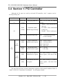
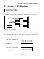
3.8 Section 5: A/D & D/A Register
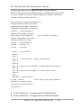
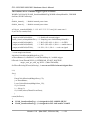
z I/O address of DA-0 = wAddrAdda
z I/O address of DA-1 = wAddrAdda + 1*4
z I/O address of FIFO = wAddrAdda
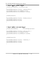
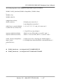
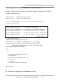
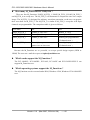
Writing data to this section will write data to the DACs and reading data from this
port will read the data from A/D FIFO. The read/write operation is given as follows:
Port
Read
Write
Section + 0
A/D FIFO.
DAC1 write.
Section + 4
Reserved
DAC2 write.
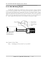
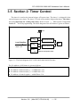
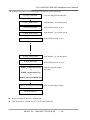
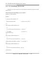
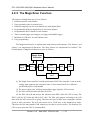
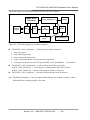
The PCI-1800/1802 provides 2 independent 12-bits D/A converters with double buffer,
bipolar voltage output. The output voltage can be ±5V or ±10V selected by J1. When the PCI1800/1802 is first power-on, the D/A will be in the floating state. The D/A will go to the
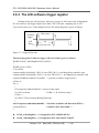
programmed state after executing D/A output command. The block diagram is given as below:
5 or 10 Vref
Section5 + 0
Select
DA1
Local Data Bus
Analog Output 1
Double Buffer
D0,D1…D11
DA2
Section5 + 4
Analog Output2
Select
Figure 4-2 : D/A output diagram.
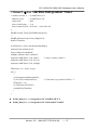
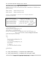
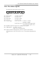
Note: The D/A output is floating after first power-on. The D/A output will be enabled after
executing D/A output command. This is the common feature of PCI-1202/1602/1800/1802.
Version: 3.8
(Mar.2007, PPH-014-38)
---- 62