1
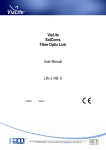
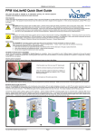
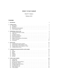
ViaLite
DVB-T
Fibre Optic Link
User Manual
LRx-D-HB-4
CR2874
14/04/11
Pulse Power & Measurement Ltd, 65 Shrivenham Hundred Business Park, Watchfield, Swindon, Wiltshire SN68TY, UK
Tel +44 (0)1793 784389 Fax +44 (0)1793 784391 Email [email protected] www.vialite.co.uk
PPM LTD 2011
2
PPM LTD 2011
Instrument Care and Safety Information
Please read the whole of this section before using your ViaLite product.
It contains important safety information and will enable you to get the
most out of your link.
Electrical Safety
The ViaLite 19” Rack Case power supply units are Safety Class 1 products (having a metal case that is
directly connected to earth via the power supply cable).
When operating the equipment note the following:
Hazardous voltages exist within the equipment. There are no user serviceable parts inside, and the
covers should only be removed by suitably qualified personnel.
The equipment does not have an isolating switch on the mains inlets. Equipment must be installed
within easy reach of a clearly labelled dual pole mains isolation switch.
Make sure that only fuses of the required rated current, and of the specified type (anti-surge, quick
blow, etc.) are used for replacement.
Optical Safety
The ViaLite RF DVB-T Transmitter modules contain laser diode sources operating at 1310nm nominal.
These devices are rated at under EN60825-1 “Safety of Laser Products” as CLASS 1 radiation emitting
devices.
When operating the equipment note the following:
Never look into the end of an optical fibre directly or by reflection either with the naked eye or
through an optical instrument.
Never leave equipment with radiating bare fibres accessible – always cap the connectors.
Do not remove equipment covers when operating.
Details of optical connections to the units, compatible fibre types and care instructions can be found
in the ViaLite system handbook. Please read this section before using the link.
Adjustment, maintenance and repair of the equipment should only be carried out by suitably
qualified personnel.
For more information on the ViaLite range of products, please refer to the ViaLite system
handbook Lxx-HB.
3
PPM LTD 2011
TABLE OF CONTENTS
1 INTRODUCTION ............................................................................... 5
1.1
ViaLite DVB-T Fibre-Optic-Link .............................................................................................. 5
1.2
Part Numbers............................................................................................................................... 6
1.3
System Description ...................................................................................................................... 7
1.4
DVB-T Antenna Installation ...................................................................................................... 9
1.5
LNA Feed ..................................................................................................................................... 9
1.6
Care of fibre optic connectors .................................................................................................. 10
2 SETTING UP AND UNDERSTANDING THE LINK .................. 11
2.1
Module Operation ..................................................................................................................... 11
2.2
Fibre Optic Cable & Connectors ............................................................................................. 12
2.3
Using the Transmitter Module ................................................................................................. 15
2.4
Using the Receiver Module ....................................................................................................... 16
2.5
Module Format .......................................................................................................................... 17
2.6
Alarms & Monitoring ............................................................................................................... 18
3 TECHNICAL SPECIFICATIONS.................................................. 20
4 MAINTENANCE AND FAULT-FINDING GUIDE ..................... 21
5 PRODUCT WARRANTY ................................................................ 22
4
PPM LTD 2011
1 Introduction
1.1 ViaLite DVB-T Fibre-Optic-Link
PPM‟s ViaLite DVB-T Fibre-Optic-Link provides a high reliability, transparent cross-site connection
between in UHF TV band.
Using optical fibre and a DVB-T antenna suitably positioned for reception from a local transmitter, a
set-top box and TV can be up to 30km from the antenna.
The position and information on the local DVB-T transmitter stations can be obtained at the Digital TV
Group website: http://www.dtg.org.uk/retailer/coverage.html
P
P
P
M
P
M
P
P
M
P
P
M
P
P
P
M
P
M
P
P
M
P
P
P
M
ViaLite
P
M
ViaLite
RESERVE PSU
LPS-R
MAIN PSU
LPS-M
The wide dynamic range of the link results in negligible degradation of the DVB-T broadcast due to
noise or interfering signals.
The use of optical fibre has a number of advantages over conventional coaxial alternatives:
Low signal loss – enabling a long link with negligible attenuation of the signal
Lightweight, highly flexible and small diameter cable
Frequency response independent of the path length
Immune to electromagnetic interference
Provides electrical isolation
PPM‟s ViaLite DVB-T product offers particular advantages:
Full DVB-T broadcast band coverage
Operation up to 30km
Compact plug-in module – up to 8 in 19” chassis
Shielded module option for use in high levels of electrical interference or over a wide operating
temperature range
Wide dynamic range for negligible signal degradation
Front panel status LEDs and rear panel alarm outputs: laser status, received light level
External mast-head LNA
5
P
M
ViaLite
ViaLite
ViaLite
ViaLite
ViaLite
ViaLite
ViaLite
ViaLite
UHF DVB-T
470-860MHz
Optical Tx
P
PPM LTD 2011
1.2 Part Numbers
This handbook covers the following RF DVB-T modules:
L R T – D 3 - 6 R - 05- S 1310
LRT : Transmitter
LRR : Receiver
6 : FC/APC
7 : E2000
R : Rack Module
M : OEM Module
D1 : DVB-T RF, 50ohm SMA
D3 : DVB-T RF, 75ohm BNC*
Transmitters
05 : -15dB Gain, user LNA feed
25: -15dB Gain, +12V LNA feed
Receivers
05 : +15dB Gain
Transmitters only
S : DFB Laser
C : CWDM
Transmitters only
DFB options:
1310 : 1310±20nm
1550 : 1550±20nm
CWDM options:
1470 : 1470±3nm
1490 : 1490±3nm
1510 : 1510±3nm
1530 : 1530±3nm
1550 : 1550±3nm
1570 : 1570±3nm
1590 : 1590±3nm
1610 : 1610±3nm
* - Not available in OEM format
Refer to the ViaLite System Handbook for further details on the following ViaLite items:
Part Number
Description
LRK1S
Case for Desktop or 19” rack installation. Accommodates up to 8 plug-in modules and 2 mains
power supplies.
LRK2S
Sub-rack for 19” rack installation. Accommodates up to 8 plug-in modules and 2 mains power
supplies.
LPS-M
Main Power Supply plug-in for LRK1S or LRK2S.
LPS-R
Reserve Power Supply plug-in for LRK1S or LRK2S.
75003
Converter sleeve. Converts plug-in module for standalone operation.
73502
Power Supply, 12Vdc, for plug-in Converter Sleeve
F6R1/x
FC/APC Patch-lead, 2.8mm jacket. Length defined in metres by “x” (1m, 2m, 5m, 10m)
6
PPM LTD 2011
1.3 System Description
1.3.1 DVB-T Reception
DVB-T Antenna
Masthead
LNA
RF Cable
Optic-Fibre Cable Link
DVB-T Box
Optic-Fibre Receiver
ViaLite
LRR-D3-6R-05
Optic-Fibre Transmitter
ViaLite
LRT-D3-6R-25-H1310
The optic-fibre link operates as follows:
The DVB-T broadcast signal from the TV antenna is amplified by the masthead amplifier and fed to the
optical transmitter module through a 75 cable. The signal is converted to an RF modulated optical
signal by the laser and associated circuitry. The light travels through optical fibre to the receiver
module where it is converted back to an RF signal by the detector diode. The broadcast signal is then
fed to the DVB-T receiver by a 75 cable.
7
PPM LTD 2011
1.3.2 Broadcast Transmission Link
Camera Radio Link
ASI Receiver
Downconverter
Optic-Fibre Cable Link
Transmission
Receiver
Optic-Fibre Receiver
ViaLite
LRR-D3-6R-05
RF Cable
Optic-Fibre Transmitter
ViaLite
LRT-D3-6R-05-H1310
The optic-fibre link operates as follows:
The signal from the camera radio link is down-converted to UHF and fed to the optical transmitter
module through a 75 cable. The signal is converted to an RF modulated optical signal by the laser and
associated circuitry. The light travels through optical fibre to the receiver module where it is converted
back to an RF signal by the detector diode. The broadcast signal is then fed to the transmission receiver
by a 75 cable.
8
PPM LTD 2011
1.4 DVB-T Antenna Installation
For the DVB-T reception configuration, a DVB-T antenna (part number: 51215) and a kit (part number:
51214) consisting of a masthead amplifier, 15M of RG59 cable with two 75 BNC and two TV
connectors are available. The antenna should be located in a position with good visibility of a DVB-T
broadcast transmitter. Information on local transmitter stations can be found on the Digital TV Group
website referred to in section 1.1. The masthead amplifier should be located close to the antenna with
approximately 1M of RG59 cable. A length of not more than 3M should connect the amplifier to the
fibre-optic transmitter using the connectors provided. At the receiver end of the optic-fibre link a short
length of RG59 connects to the DVB-T box using the connectors provided.
1.5 LNA Feed
In the majority of applications, this product will be used to extend the range of coaxial cable. In some
cases, the coaxial cable is used to power a low noise amplifier and/or downconverter. Since the fibre
has no electrical conductivity, the optical transmitter has been designed to provide voltage feed at the
head end of the link (near the antenna amplifier).
Modules are available with two LNA options. The first (recommended for DVB-T reception from fixed
broadcast transmitters) has a +5V or +12V (80mA) feed built into the transmitter module. This is
designed to operate with the UHF masthead amplifier supplied by PPM, but will operate with a number
of popular masthead units. Please contact PPM for suitability.
The second option (recommended for complex systems such as reception of downconverted signals
from COFDM radio cameras) does not supply a voltage, but facilitates connection of any supply voltage
up to 36V to the rear panel. This voltage will then be transferred to the RF input to the transmitter for
powering low noise blocks. The maximum current for this arrangement is 350mA. The equipment is
protected with a thermal fuse.
All information in this section refers to fibre optic transmitter modules only. LNA voltages are fed out
through the RF input connector on the Tx modules.
OEM Modules
Modules in this range DO NOT offer an internally generated LNA feed voltage.
Some modules do offer an ability to route a user fed LNA voltage through PIN 13 on the 14-way
header, details shown below.
When using PPM Outdoor Enclosure, external LNA feed is available via the outdoor enclosure
motherboard.
Plug-In Modules
Depending on bandwidth there are options for internally generated 5V or 12V LNA feed, and options to
route a user fed LNA voltage through PIN 14 of the rear 15-way D-sub Connector, details shown below.
It is not possible to route a user fed LNA voltage through PIN 14 of the rear 15-way D-sub Connector
on any modules that have been purchased with internally generated LNA feeds.
9
PPM LTD 2011
Module Series
Module
Plug-In Modules
OEM Modules
Special Options
(please contact PPM when
ordering, no part code
exists)
Standard & Standard Options
DVB-T Link
„D‟ Series
UHF/DVB-T
200 – 900 MHz
External +/-36Vdc
330mA LNA feed
allowed. To enable
apply voltage to
PIN 13 of the 14
way header
connector.
LRT-D3-6R-0x-S1310
(0 in Transmitter part number
signifies standard external feed
upto +12Vdc at 350mA max
from PIN 14 of the 15-way Dsub connector on chassis or
converter sleeve)
Factory option for
feed internally generated 5Vdc
feed @80mA)
LRT-D3-6R-2x-S1310
(2 in Transmitter part number
signifies standard internally
generated 12Vdc feed @80mA)
1.6 Care of fibre optic connectors
Fibre optic connectors are more sensitive to damage and contamination than electrical connectors are.
In order to maintain full performance from your fibre optic link system, it is necessary to take care to
protect the connectors from damage and to keep them clean.
The cable connectors should always be cleaned before they are used, even if they have been protected
by dust caps.
A cleaning kit is provided with the equipment for this purpose.
When the fibre optic cables are not connected, it is essential that the cable and module connectors be
protected by the dust caps provided with the system. Failure to do so may result in damage to the fibre
ends, which are critical to the system performance.
Please refer to section 2.2 for fibre optic cable handling and cleaning instructions.
10
PPM LTD 2011
2 Setting up and Understanding the Link
Please read fully document Lxx-HB for information on installing your ViaLite equipment before
commissioning your RF link system.
2.1 Module Operation
The DVB-T fibre optic link modules are available as 19” Plug-in modules.
2.1.1 Plug-in Module
The plug-in modules are designed for use in PPM‟s ViaLite 19” Rack Case. The plug-in module may
also be used in a standalone configuration with a Converter Sleeve. The module is powered from the
19” Rack Case backplane and all connections are on the rear panel of the module.
Power/Alarm - DIN 41612 backplane connector providing power and connectivity to the module alarm
outputs.
RF - BNC connector for applying the UHF input (to the optical transmitter) or monitoring the UHF
output (from the optical receiver) signal. Depending on the option selected, the transmitter module may
have an LNA feed for powering a LNA or downconverter.
Optical - FC/APC female receptacle for connection to the cross-site fibre optic cable.
Power/Alarm
Connector
RF
Connector
Optical
Connector
11
PPM LTD 2011
2.2 Fibre Optic Cable & Connectors
2.2.1 Care of fibre optic connectors
Modern optical connectors offer very high levels of performance, reliability and repeatability. However,
they are more sensitive to damage and contamination than electrical connectors. In order to maintain
full performance from your fibre optic link system, it is necessary to take care to protect the connectors
from damage and to keep them clean.
The light carrying core of a single-mode optical fibre is 8 m in diameter, and in a mating connector
pair, the two cores must be aligned to better than 1 m in order to minimise insertion loss. The optical
connectors used in PPM‟s systems maintain their performance even after hundreds of matings, as long
as they are kept clean. Dirt or contamination may result in the core being obscured or misaligned, and
this in turn results in high insertion loss and poor link performance.
The following precautions should be taken to maintain the performance of your link.
The cable connectors should always be cleaned before they are used, even if they have been
protected by dust caps.
When the fibre optic cables are not connected, it is essential that the cable and module connectors
be protected by the dust caps provided with the system.
2.2.2 Connector and Cable Types
All ViaLite RF DVB-T modules use single-mode (8µm/125µm) fibre terminated with FC/APC optical
connectors. Cross-site cables are available in standard (3mm diameter) and heavy-duty (8mm diameter)
variants.
FC/APC is an industry standard for angle-polished optical connectors and must not be confused
with standard FC/PC connectors. The two connector types are not interchangeable and mating
one with the other will damage both the cross-site interconnect and the module.
2.2.3 Connecting and Disconnecting
The cable connectors should be cleaned before every connection (see 2.2.4).
To connect FC/APC optical connectors, align the centre ferrule on the cable connector with the female
receptacle in the module. There is a lug on the side of the ferrule, which must align to the gap in the
receptacle. When they are in alignment, push the plug gently home and finger tighten the knurled collet
onto the receptacle. See Figure 1 below.
To disconnect FC/APC connectors, unscrew the knurled collet on the plug and gently withdraw the
plug. Replace the dustcaps on both the receptacle and the cable connector.
12
PPM LTD 2011
Figure 1
(a) showing FC/APC connector with dust cap removed, (b) showing alignment of the lug on the side of
the ferrule, which must match the gap in the receptacle shroud before gently pushing the plug home and
finger tighten the knurled collet nut onto the threaded receptacle.
(a)
(b)
2.2.4 Care and Cleaning
The cleaning kit (provided) should be used in conjunction with the instructions for cleaning prior to
initial installation and initial use. Each dry-wipe card and receptacle cleaning stick should only be
used once and then discarded. Additional cleaning materials can be purchased from PPM.
The cable optical connectors should then be cleaned before every use, even where they have been
protected with dust caps.
If the cables have become excessively dirty and satisfactory operation cannot be achieved using "drywipe cleaning", the following cleaning process should be employed.
Cleaning items required:
Lint free fibre industrial cleaning tissue
Reagent grade Isopropyl Alcohol (IPA)
Air duster
Cable Connector Cleaning:
Dampen a patch of cleaning tissue with IPA and clean all surfaces of the plug ferrule
Using a dry cleaning tissue, dry the ferrule and polish the end face.
Using the air duster, blow away all residues from the end of the connector.
Module Female Receptacle Cleaning (only recommended if problems are being experienced)
Twist a cleaning tissue to form a stiff probe, and moisten with IPA. Gently push the probe into the
receptacle and twist around several times to dislodge any dirt.
Repeat the above process with a dry tissue.
Using the air duster, blow away all residues from the receptacle.
13
PPM LTD 2011
Important Notes
IPA is flammable. Follow appropriate precautions and local guidelines, when handling and storing
IPA
IPA can be harmful if spilt on skin. Use appropriate protection when handling
It should only be necessary to clean the female receptacles on the modules if problems are being
experienced
Never inspect an optical fibre or connector with the naked eye or an instrument unless you
are convinced that there is no optical radiation being emitted by the fibre. Remove all power
sources to the module, and isolate the optical fibres
2.2.5 Minimum Bend Radius
Because the optical fibre is made of glass, it is important not to subject it to a tight bend radius. For this
reason, the fibre has a minimum bend radius (MBR) specification, beyond which the cable cannot be
bent without excessive loss or damage occurring.
MBR specifications for PPM fibre are given in the ViaLite System Handbook Lxx-HB.
14
PPM LTD 2011
2.3 Using the Transmitter Module
2.3.1 Connecting the Transmitter Module
Connect the transmitter to the power supply, the fibre optic cross-site cable and the RF DVB-T signal as
described in section 2.1. The RF input signal applied to the BNC Signal Connector should be within the
maximum and minimum signal levels given in the specifications in section 3.
CAUTION
On some modules, there is +12Vdc connected to the RF co-axial input to provide power to the masthead
amplifier. The transmitter module should be turned off when connecting to the masthead amplifier and
antenna.
2.3.2 Front Panel Indicators
The transmitter has two front panel LEDs to indicate the module status.
Power LED
Status LED
OFF
Standard
version
Unit is Off
Ext. Power Feed
option
Unit is Off
Standard
version
Unit is Off
Ext. Power
Feed option
Unit is Off
GREEN
Unit is OK
Unit is OK
Laser is OK
Laser is OK
RED
Internal Fault
Internal Fault
or
DC Feed current limit
Laser Failure
Laser Failure
2.3.3 Alarm Output
When the plug-in transmitter module is fitted in an LRK 19” Rack Case, an open collector alarm output
is available via the LRK backplane alarm concentrator connector.
There are two monitor outputs for each module position on the LRK alarm concentrator connector:
ALMnA – Open collector output. Indicates laser failure OR DC Feed over-current
ALMnC – Analogue monitor is not used on the RF DVB-T Transmitter
(n indicates module position 1 to 8)
The open collector alarm output sinks current in the absence of an alarm condition. When an alarm
occurs, the output goes into a high impedance state. Refer to section 2.6 for details of the alarm
interface.
15
PPM LTD 2011
2.4 Using the Receiver Module
2.4.1 Connecting the Receiver Module
Connect the receiver to the power source, fibre optic cross-site cable and RF signal as described in
section 2.1.
2.4.2 Front Panel Indicators
The transmitter has two front panel LEDs to indicate the module status.
Power LED
Signal LED
OFF
Unit Off
Unit Off
GREEN
Unit OK
Link OK
RED
Internal Fault
Low light: Optical loss >20dB
The “Low Light” alarm is triggered when the light level at the receiver is below a preset limit. This
threshold is set to be 20dB (optical) less than the nominal system gain.
2.4.3 Alarm and Monitor Output
When the plug-in receiver module is fitted in an LRK 19” rack chassis, an open collector alarm output
and a monitor output are available via the LRK backplane alarm concentrator connector.
There are two alarm outputs for each module position on the LRK alarm concentrator connector:
ALMnA – open collector output. Low received light level
ALMnC – Analogue Received Light Level voltage *
The open collector alarm output sinks current in the absence of an alarm condition. When an alarm
occurs, the output goes into a high impedance state. Refer to section 2.6 for details of the alarm
interface.
* RLL Output Voltage = 7.75V for a gain of 0dB and reduces by 0.125V per dB of RF link loss due to
losses in the optical path.
16
PPM LTD 2011
2.5 Module Formats
35.5mm
128.4mm
175mm
Plug in Module
55mm
20.8mm
80mm
OEM Module
17
PPM LTD 2011
2.6 Alarms & Monitoring
2.6.1 Module Alarm Output
The circuit below shows how the alarm output should be configured for all types of ViaLite module.
The switch (to the left of the dotted line) is internal to the module. The circuitry to the right of the
dotted line is provided by the system user*.
In the presence of an alarm condition, the module will act as a high impedance node and will NOT sink
current. This is a fail-safe system in that an alarm condition will be raised when a module is not
present. This is an important factor when commissioning link management systems, as blank module
positions will register module faults.
Internal to
module
External to
module
VEXT
Pull-Up
Resistor
Alarm
Ground
This circuitry is also provided by the Redundancy Switch module and the Alarm Concentrator
module. When either of these modules are used, the alarm outputs cannot be considered "VOLT
FREE". This is because the Redundancy Switch module and the Alarm Concentrator modules use
the same module alarm outputs to detect whether a unit has failed. When these modules are used, a
voltage of between 5V and 12V may be present on the 'Alarm' output line when the module is in the
failed mode. When the module is working correctly, the voltage on the 'Alarm' output line will be
0V (+1.0/-0). If true "VOLT FREE" contacts are required, please consult PPM.
Maximum current = 50mA
Maximum voltage = 15V
2.6.2 Module Monitor Output
All modules also provide an analogue monitor output for monitoring the condition of the Optical
transmitter / receiver. Details of the monitor can be found in the technical specifications in section 3 of
this document.
18
PPM LTD 2011
2.6.3 Module Alarm & Monitor Connection
Rack Modules
Connection is made to the module by the 15-way D-Sub connector on the rear of the rack backplane.
Pin Number
Function
1
Do Not Connect
2
Do Not Connect
3
Do Not Connect
4
Do Not Connect
5
Alarm Output
6
+12V from rack supply
7
External Feed (option)
8
Ground
9
Do Not Connect
10
Do Not Connect
11
Do Not Connect
12
Do Not Connect
13
Analogue Monitor Output
14
External Feed (option)
15
Ground
8
1
9
15
9
View looking into connector
OEM Modules
Connection is made to the module by the 14pin boxed header Molex (C-Grid III), 0.1” dual row
connector. All OEM modules are supplied with a 250mm interface cable.
Pin
Number
1
2
3
4
5
6
7
8
9
10
11
12
13
14
Name
Tx_A
Rx_A
Tx_B
Rx_B
Dig_Alm
RTS
+Va
0v
Rx_232
Tx_232
0v
Det_Opt_Tx
LNA_Feed
An_Alm
Cable
Colour
Pink
Pink
Pink
Pink
Orange
Pink
Red
Black
Pink
Purple
Black
Pink
White
Green
Function
Do Not Connect
Do Not Connect
Do Not Connect
Do Not Connect
Alarm Output
Do Not Connect
+12V from supply
Ground
Do Not Connect
Do Not Connect
Ground
Do Not Connect
External LNA Feed (option)
Analogue Monitor Output
2
14
1
Top view, 14 pin header
19
13
PPM LTD 2011
3 Technical Specifications
Bandwidth
Bandwidth
Gain
RF Link Gain at 0dB optical loss
200 – 900MHz
0dB 3dB
Subtract [2 x Optical Loss]dB for >0dB optical loss
Optical Losses: Fibre = 0.4dB/km typ. Connectors = 0.5dB per connector typ.
Gain Stability over Temperature
Tx
Rx
< +/-3dB over operating range
<0.08dB/ C below 40 C typ. <0.1dB/ C above 40 C typ.
<0.05dB/ C typ.
Dynamic Range
Input Third Order Intercept
Input P1dB
>0dBm
>-10dBm
Noise Figure
<18dB, at 0dB optical loss
User Interface
Input/Output Impedance, VSWR
75 , 2:1
Power LED
Transmitter Status LED
Receiver Status LED
Transmitter Alarm Output
Indicates DC power is applied to the module
Green: Transmitter laser functioning
Red: Transmitter laser degraded
Green: Received light level above threshold
(threshold factory set to nominal 20dB optical / 40dB electrical loss)
Red: Received light level below threshold
Current sink "Laser Degraded" Alarm
Receiver Alarm Output & Monitor
Current sink "Light Low" Alarm
Analogue Received Light Level (RLL) monitor. RLL monitor voltage = 7.75V for a gain of
0dB and reduces by 0.125V per dB of RF link loss due to losses in the optical path.
RF Connector
75
LNA Supply Voltage Option on optical
transmitter
+12VDC @ 350mA external feed
+12VDC @ 80mA internal feed
Optical Connector
E2000/APC Narrow key, >60dB return loss, Suhner FCPC-Z/M-A601
Monitor & Alarm Interface
Rack plug-in module
Shielded remote module
Converter Sleeve
15pin female D-type on 19” rack case backplane
8pin female Lemo 1B
15pin female D-type
Power Consumption
Transmitter <4.5W, Receiver <4W at 12VDC
Operating Conditions
Absolute Maximum RF Input (RF in)
>+15dBm, 20Vdc
Optical
BNC Female
0.5VDC
>60dB return loss. E2000/APC Narrow key narrow key connector. Use with other types may
compromise system performance.
Operating Temperature
Rack plug-in module
Shielded remote module
0 C to +40 C
-20 C to +50 C
Storage Temperature
-40 C to +70 C
Optical Characteristics
Wavelength
1310+/-20nm
Fibre
Single-mode 9/125, Corning SMF28 or equivalent
Output Power
+4.5dBm/3mW nominal
All parameters are specified after a 15minute warm-up.
20
PPM LTD 2011
4 Maintenance and Fault-Finding Guide
Refer to the following table that gives a list of commonly encountered problems and suggested
solutions.
Fault
Possible Causes
Solution
Power LED does not light
on Plug-in module when
plugged into Converter
Sleeve.
Power source not connected.
Connect power source.
Module not plugged fully into
Converter Sleeve
Plug module in fully.
Power LED lights up RED.
External LNA feed is in current
limit.
Check the masthead amplifier and
RF cable for a short circuit.
Status LED lights up RED.
Tx: Laser Failure.
Return to local PPM office.
Rx: Low optical level.
Clean the optical connectors.
No optical signal.
Check optical link for breaks and
the connections for tight bend radii
etc.
The ViaLite range of RF DVB-T Transmit and Receive Modules are precision engineered and calibrated
for optimum performance and accuracy before dispatch.
However, in the event of any problems or queries arising about the equipment, please contact PPM or
your local agent.
21
PPM LTD 2011
5 Product Warranty
The Company guarantees its products, and will maintain them for a period of three years from the date
of shipment at no cost to the customer. Extended warranty options are available at the time of purchase.
Please note that the customer is responsible for shipping costs to return the unit to PPM.
The Company or its agents will maintain its products in full working order and make all necessary
adjustments and parts replacements during the Company‟s normal working hours provided that the
Customer will pay at the rates currently charged by the Company for any replacements made necessary
by accident, misuse, neglect, wilful act or default or any cause other than normal use.
Claims must be made promptly, and during the guarantee period.
IMPORTANT: Please contact both your selling agent and PPM prior to returning any goods for Warranty or
Non-Warranty repairs. Goods will not be accepted without a valid Goods Return Number
(GRN).
22
PPM LTD 2011
ViaLite RF DVB-T FIBRE OPTIC LINK HANDBOOK (LRX-D-HB) ISSUE 4 CR 2874
PULSE, POWER & MEASUREMENT LTD. 2011
NO PART OF THIS DOCUMENT MAY BE REPRODUCED OR TRANSMITTED IN ANY FORM WITHOUT PRIOR WRITTEN PERMISSION.
PPM LTD. 65 SHRIVENHAM HUNDRED BUSINESS PARK, SWINDON. SN6 8TY. UK.
TEL: +44 1793 784389 FAX: +44 1793 784391
EMAIL : [email protected]
WEBSITE : WWW.VIALITE.COM