1
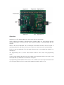
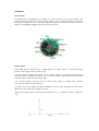
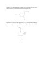
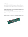
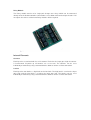
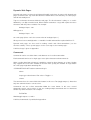
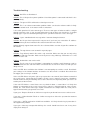
NETIOM-STD
User Manual
About This Manual
This manual provides a detailed description of the operation and features of Netiom. It
assumes that the reader is familiar with network terminology and therefore does not give any
detailed descriptions of networks or their operation.
If you are not familiar with networking then it may help to read the “Network Terminology”
document.
PC based software is provided which provides a graphical interface to the programming
features of Netiom. This manual makes reference to this software in the explanations for the
set up procedure.
It is not necessary to read the whole manual before setting up Netiom as it is unlikely that you
will use all of its features. For small networks the Quick Start section should get you up and
running so that you can view web pages on a browser.
If you encounter problems with the Quick Start then it likely that you have some sort of
problem with network addressing. If so refer to that section. The Introduction and Operation
section may also help with problem solving.
Introduction
Netiom is a network enabled Input / Output module. It consists of:
16 Digital Inputs
16 Digital Outputs
4 Analogue Inputs
1 Serial Port
1 Ethernet Port
Three LEDs are provided which show the status of the ethernet connection. A link is provided
to switch between active mode and programming mode.
The module can act as an HTTP server with up to 32K of web space. It can generate e-mails
and act as a client to a remote server.
Netiom will work on both local networks and wide area networks such as the Internet.
To run Netiom you will need:
A 12 Volt d.c. power supply.
A null modem serial lead (for programming).
An ethernet cable to connect to the network.
Operation
Netiom has 3 LEDs which indicate the status of the ethernet connection.
Green indicates that Netiom is connected to the network. When it is on it indicates that the
network connection is present but not necessarily that Netiom is communicating with the
network.
Amber is the receive indication. This is normally on and switches off when data is received. In
normal operation this will flicker off every few seconds as it detects normal network polling.
Red is the transmit indication. This will switch off when data is transmitted from Netiom. It is
normally on.
The programming link is used to switch Netiom between active mode and programming
mode.
In active mode Netiom will connect to the network and respond to ethernet messages. It will
not respond to any commands issued on the serial port.
In programming mode Netiom will not access the network but it will accept commands from
the serial port. When the link is removed all network connections will be reset.
Quick Start
1. Place the programming link in position.
2. Connect the network to Netiom with an ethernet cable.
3. Connect a 12 Volt d.c. power supply to the power terminals.
4. The LED’s should now be illuminated. The amber LED may flicker occasionally.
5. You may now want to verify the settings using the Netiom Interface software.
6. Install and run the Netiom Interface Software.
7. Select the PC comms port you will be using. This is on the General page.
8. Connect a null modem lead between the PC comms port and the Netiom serial port.
9. Press the “Read From NETIOM” button. You can now review the settings.
10. The next step will depend on your network settings. If you have a DHCP server (typically
an ADSL router) proceed from section “With DHCP Server” otherwise go the section “Without
DHCP Server”.
With DHCP Server
11. Ensure that the “Get Address Automatically” box is checked on the server page of the
Netiom Interface software. If it is not checked, the check it and download to Netiom using the
“Write To NETIOM” button on the general page.
12. Remove the programming link. The red LED should now flicker once or twice.
13. Wait for about 5 seconds and replace the programming link.
14. Read the data back from Netiom as before.
15. The assigned IP address will now be displayed on the Server page. If this reads 0.0.0.0
then the DHCP process has failed and it will be necessary to set up the IP address manually.
Follow the “Without DHCP Server” section instructions.
16. Make a note of the IP address and go to step 22.
Without DHCP Server
17. You will need to set up the addressing manually. Uncheck the “Get Address
Automatically” box on the server page of the Netiom Interface software.
18. If there are a large number of devices on your network you will need to be assigned an IP
address from your network administrator. If there are only a few PCs you can determine their
address from a command prompt. Type in “ipconfig” and the settings will be returned. Make a
note of each one and choose an address close to the ones returned changing only the fourth
number. For example if your network is using 192.168.0.2 and 192.168.0.5 try using
192.168.0.6.
19. Enter the obtained number into the IP address boxes. You should be safe using
192.168.0.1 for the gateway address and 255.255.255.0 for the Submask.
20. Download the new data to Netiom using the “Write To NETIOM” button on the general
page.
21 When the download is complete remove the programming link.
22. You should now be able to connect to Netiom on a web browser. Enter the IP address in
the address field of the browser and the web pages should appear.
Interface Software
PC based software is provided to provide a graphical interface to programming Netiom.
On the opening page there are controls for loading and sending data and a logging area
which will show a log of activity as well as any problems encountered.
Sections are provided which cover:
Server and General parameters.
e-mail options.
Client connections.
Web page selection and downloading.
Data
Data can be written to Netiom or read from it via the serial port at 19200 baud. Note that the
programming link must be in place before communications can be established with Netiom.
The best way to use the program is to read data from Netiom, modify it and then write it back.
In general only data that is needed will be sent to Netiom. For example if e-mail is disabled
then none of the E-mail data will be downloaded. This means that you can temporarily disable
a function without affecting data held within Netiom.
At start up the program will load a set of defaults from the file “DefaultConfig.txt”. If you need
a different set of defaults you can overwrite this file with your own values. If you have several
different configurations then these can be saved as separate files.
Before sending data to Netiom the data is checked for any inconsistencies and will not
proceed if any are found. For example, if e-mail has been enabled but no IP address has
been specified then data will not be sent to Netiom as this might cause unpredictable
operation. If problems are encountered a list is written to the logging window.
During the write operation to Netiom all data is read back and compared with the data sent. If
there are any problems then they will be reported in the log window.
Web Pages
All web page selection and downloading is done from the “Web Page” section.
You can specify a list of pages which will be used to create an image to download to Netiom.
These do not need to be in a single folder but it may be more convenient if they are. When
you download the web pages they are copied to a sub folder called “TempWebPges”. They
are then combined into an image file and sent to Netiom. The copied files are then deleted.
Do not place any other files in the “TempWebPges” as they will be included in the image and
then deleted.
It is not possible to read the web pages back from Netiom through the serial port and so no
checking is performed. You will need to check that they have been successfully downloaded
using the network.
Setting The Address
In order to function properly on a network Netiom needs know the following information:
IP Address
Gateway Address
Submask
Netiom is able to collect this information automatically if the network has a DHCP server.
However if these addresses are obtained automatically they will be dynamic and can change
with time. If Netiom is used as a server this can cause problems as clients will not know the
current address.
To obtain an address automatically check the “Get Address Automatically” box. After you
download the data to Netiom and remove the link Netiom will attempt to obtain the relevant
information.
To set up the addresses manually uncheck the” Get Address Automatically” box and enter the
addresses in the appropriate edit boxes. Each box must contain a number in the range 0 to
255. The default values are:
IP Address: 192.168.0.6
Gateway Address: 192.168.0.1
Submask: 255.255.255.0
These values should be OK for small networks with only one or two computers and a gateway
router.
If you need to change them you will need to ascertain the values from the network. For local
networks there are three address ranges:
10.0.0.0 to 10.255.255.255
172.16.0.0 to 172.31.255.255
192.168.0.0 to 192.168.255.255
The best way to find free addresses is to log on to the gateway router as this will keep track of
all the attached devices. It will also show its own IP address which should be used as the
Gateway Address.
You can find the settings on any local PC running Windows by going to the command prompt
and typing “config”. This will return the IP Address of the PC, the Gateway Address and the
Submask. If you only have one PC and gateway router then use the last two values for the
Gateway Address and Submask and increment the last digit of the IP Address by 1.
Device Name
This is an optional field and need not be filled in. It is used as a tag field in dynamic web
pages and is useful as a way of identifying individual Netioms if you plan to use more than
one. The maximum size is 8 characters.
Server Passwords
With the “Enable Server Password” box unchecked web pages will be available to anyone
who accesses the Netiom from a browser.
With the box checked a user name and password will be required when the user first
accesses the Netiom. Once the user name and password has been entered it will be valid for
the remainder of the session.
Both user name and password fields will need to be filled in if this option is selected.
Maximum size for both fields is 8 characters. Note that these fields are case sensitive.
Serial Port
With the programming link in place the serial port always runs at 19200 baud.
In active mode you can specify the baud rate so that Netiom can communicate with external
equipment. Netiom can support baud rates in the range 2400 to 38400 baud.
Netiom will store incoming serial data in a working buffer until it deems that the data string is
complete. Once complete the data is made available for dynamic web pages or is used to
trigger an e-mail or client connection (if enabled).
You can specify either a carriage return/line feed pair (CR/LF) indicates that the data is
complete or use a timed methology i.e. not data for a fixed period. If the latter is chosen then
the timeout value can be specified in the range 20mS to 20 seconds.
HTTP Settings
HTTP Port
Normally web browsers use port 80 to initiate a connection to a web server. However you can
program Netiom to listen on any port in the range 1 to 65535. This would normally only be
necessary if Netiom is connected to an external network such as the Internet. If you have
another HTTP server or you are running more that one Netiom then separate ports will be
necessary for port forwarding. It may also be useful as an additional security method to help
prevent unauthorised users stumbling across your site.
If you do change your HTTP port number Netiom will still be accessible from browsers by
specifying the port number with the address:
http://192.168.0.6:8080/
will connect to IP Address 192.168.0.6 using port 8080.
Watchdog
The watchdog facility can be used to monitor network activity. If there has been no HTTP
activity for a preset period then output 1 will be activated for approximately 30 seconds. This
facility is useful only if you know that the Netiom is going to be accessed regularly and can be
used to trigger a local warning or to reset a router.
The timeout can be set in the range 1 to 1000 minutes.
MAC Address
This field shows the MAC address of the Netiom. It is not possible to change this number and
is provided for information only.
E-mail
General
Netiom can generate e-mails in response to events on its inputs. It uses SMTP protocol with
“plain auth login”. This means that Netiom will supply a user name and password to the e-mail
server.
In order to enable Netiom to send e-mails you will need to:
Check the “Enable e-mail” box.
Specify the IP address of the e-mail server.
Specify Account Name and Password
Specify the e-mail Address of the sender
Specify the e-mail Address of the receiver
Account
Most of this information is the same as you would use to set up an account on a PC. The
main difference is that the e-mail server will use a URL. Netiom does not have the ability to
resolve URLs so it will be necessary to look it up. There are several sites on the Internet,
which provide a look up service. If you have not done this before try:
http://www.kloth.net/services/dig.php.
The e-mail Address of the sender should be one that you use with this account. The e-mail
Address of the receiver should be (obviously) the address to which the e-mail should be sent.
The maximum size of the fields are:
Account Name 24 characters
Password 8 characters
e-mail To 32 characters
e-mail From 32 characters
If you are having difficulty connecting to the e-mail server you can record the server
responses via the serial port in a program such as HyperTerminal. Check the “View Server
Messages” box and Netiom will repeat all incoming messages from the e-mail server out to
the serial port. This may give an indication as to what is going wrong. Note that Netiom will
use the baud rate setting (Serial Port section) and that the programming link will need to be
removed before e-mails are generated.
Note that e-mails will not be generated while the programming link is in place. The baud rate
of the serial port will be that selected under the Serial Port section.
Triggers
E-mails can be triggered from any of the digital or analogue inputs or from serial port
messages.
Digital inputs can trigger e-mails when they go high or when they go low or both. These are
selected by checking the associated boxes in the “Trigger Low on Inputs” and “Trigger High
on Inputs” sections. There is no limit on the combinations of high or low triggers.
Analogue inputs can trigger e-mails when their values exceeds a preset level and / or falls
below a preset level. Each input can have different values for above and below levels. So for
example if the above level was set to 600 and the below level was set to 500 an e-mail would
be generated when the input level reached 600 or when it fell below 500.
In order to prevent multiple e-mails being generated from analogue inputs a hysteresis value
can be specified. For “above” values, after an e-mail is generated, the input level would need
to fall below the “above” level minus the hysteresis value and then back to the “above” level
again before a second e-mail is sent.
Thus taking the value of 600 (above) with a hysteresis value of 10 an e-mail would be
generated when the input value reached 600. If the input value fell to say 595 and then
returned to 600 a second e-mail would not be generated. The level would have to reach 590
before returning to 600 before another e-mail is generated.
Similarly with “below” levels the hysteresis value would be added to the “below” value.
If you do not want to generate e-mails from these inputs then the “above” level should be set
to 1024 and the “below” level should be set to 0.
e-mails can also be triggered from the serial port. Each time a serial port message is received
e-mail is generated.
E-mail Content
The subject and message body of the e-mail can be customised using dynamic web page
files. These have fixed names: for the subject “esub.cgi” and for the body “email.cgi”. These
files can use any of the scripts used in the standard web page files.
If file “esub.cgi” is not present Netiom will use “NETIOM Message” as the subject. If
“email.cgi” is not present Netiom will use “Test Message” as the body of the e-mail.
Netiom will process the dynamic web page files after connection to the e-mail server has
been established. Normally this will happen within 1 or 2 seconds but there are times when
this period may be extended to several seconds if there are connection problems. Therefore if
the triggering mechanism is transitory it may have reverted to its normal condition before the
e-mail is actually sent.
In the event of a problem in sending an e-mail, Netiom will wait approximately 10 seconds
and re-try. If there are further problems Netiom will continue re-trying for a total of 10
attempts. If there has been no success at this point no further attempts will be made until
another e-mail is generated.
Client
General
Netiom can act as a client connecting to a remote server in response to events on its inputs
and/or on a timed basis.
In order to enable Netiom to act as a client you will need to:
Check the “Enable Client” box.
Specify the IP address of the server.
Specify which port to use.
Connecting
The IP Address of the server is in the same format as previous IP addresses. The port
number will be dependent on the software running on the server.
To connect to the server on a timed basis check the “Timed Connect” box and specify the
period between connections. This period can be in the range 10 to 65535 seconds. If the
“Timed Connect” box is checked Netiom will attempt to connect to the server approximately
10 seconds after power has been applied or the programming link has been removed. After
the connection has been established it will then wait for the programmed period before reestablishing contact.
Once connected the server should send the message “SEND”. Netiom will then look for a file
called “client.cgi” and then process the file and send it to the server. The behaviour will now
depend on other options.
If the “Stay on Line” box is checked Netiom will keep the connection open. The server can
then send commands to Netiom. The connection will then remain open until Netiom receives
a “CLOSE” message from the server at which point the connection will be closed.
While connection is open it is possible for something to go wrong at the server, at Netiom or
somewhere in between. Netiom will monitor the connection and if it has not received a
command from the server for a preset period it can close the connection and try to reestablish the connection (after a 10 second wait). This time can be set using the “Idle
Disconnect Time” option in the range 10 to 65535 seconds.
If the “Stay on Line” box is not checked Netiom will wait 3 seconds for a “CLOSE” command
from the client and if it has not been received it will automatically close the connection.
If for some reason Netiom cannot contact the server it will continually re-try every 10 seconds
until a connection is established. If the watchdog feature is enabled it can activate output 2
after the specified number of re-tries. The output will be active for approximately 30 seconds
and then the procedure will be repeated until the connection is established.
Triggers
The procedure for generating a connection is the same as the mechanisms for generating emails but are repeated here for completion.
Client connections can be triggered from any of the digital or analogue inputs or from serial
port messages.
Digital inputs can trigger Client connections when they go high or when they go low or both.
These are selected by checking the associated boxes in the “Trigger Low on Inputs” and
“Trigger High on Inputs” sections. There is no limit on the combinations of high or low triggers.
Analogue inputs can trigger Client connections when their values exceed a preset level and /
or falls below a preset level. Each input can have different values for above and below levels.
So for example if the above level was set to 600 and the below level was set to 500 a client
connection would be generated when the input level reached 600 or when it fell below 500.
In order to prevent multiple Client connections being generated from analogue inputs a
hysteresis value can be specified. For “above” values, after an Client connection is generated,
the input level would need to fall below the “above” level minus the hysteresis value and then
back to the “above” level again before a second Client connection is made.
Thus taking the value of 600 (above) with a hysteresis value of 10 a Client connection would
be generated when the input value reached 600. If the input value fell to say 595 and then
returned to 600 a second connection would not be generated. The level would have to reach
590 before returning to 600 before another connection is made.
Similarly with “below” levels the hysteresis value would be added to the “below” value.
If you do not want to generate Client connections from these inputs then the “above” level
should be set to 1024 and the “below” level should be set to 0.
Client connections can also be triggered from the serial port. Each time a serial port message
is received a Client connection is established.
Pings
Netiom will respond to network pings. To ping Netiom from a PC use the command line ping
followed by its IP address. For example:
ping 192.168.0.6
Hardware
Connections
The digital inputs and outputs are available via screw terminals or a 10 way headers. The
headers also have power pins so that auxiliary modules can be powered directly from Netiom.
Each of the headers has the same pin assignment regardless of whether they are inputs or
outputs. The following diagram shows the pin arrangement:
Digital Inputs
Each digital input is connected to a CMOS gate via a 100K resistor. It is pulled up to the
internal 5 Volt supply rail via a 10K resistor.
The input can be directly interfaced to TTL and CMOS outputs. The input voltage should not
exceed 5 Volts. In addition the inputs can use clean contacts referenced to 0 Volts or open
collector outputs again referenced to 0 Volts.
If the driving modules do not share the same power supply as Netiom then it will be
necessary to common their 0 Volt lines.
The inputs are scanned with a timebase of 100mS. Thus the input signal must be present for
200mS in order to guarantee Netiom seeing it.
With the input high or open circuit Netiom will report it as a “1”, otherwise it will be reported as
a “0”.
Outputs
Outputs are open collector and can be used to drive relays solenoid LEDs etc. Optional LED
and relay modules are available which plug directly into the 10 way header.
Note that if these outputs are to drive inductive loads such as relays and motors then the load
must have some form of back EMF suppression fitted. IF SUPPRESSION IS NOT FITTED
THEN THE OUTPUT DEVICE WILL BE DAMAGED. The following diagram shows how to
interface the VIOM output to a relay.
Analogue Inputs
The analogue inputs cover the range 0 to 5 Volts. If a larger range is necessary then it will be
necessary to use a potential divider on the input.
Measurements are referenced to the internal 5 Volt supply rail which has an accuracy of 5%.
The resolution of the A/D converter is 10 bits. All reported values for the inputs will be in the
range 0 to 1023.
For the highest accuracy the input impedance should be less than 2K ohms. Higher values
are possible but the accuracy will be reduced and there will be increased noise levels.
The voltage on the input should not exceed 5 Volts. If higher voltages are possible (e.g. if you
are using a potential divider) then you must ensure that voltages higher than 5 Volts cannot
be present under start up or fault conditions.
If the driving modules do not share the same power supply as Netiom then it will be
necessary to common their 0 Volt lines.
Hardware Accessories
Display Module
The display module consists of 8 LEDs which can be connected directly on to the Netiom
controller. Connection is via a ribbon cable to the output header. If all 16 outputs are to be
displayed then two VIOM Display modules will be required.
Relay Module
The Relay module consists of 8 single pole change over relays which can be connected
directly on to the Netiom controller. Connection is via a ribbon cable to the output header. If all
16 outputs are to be used then two Relay modules will be required.
Internal Elements
Counters
Each input has associated with it a 16 bit counter. Each time the input goes high the counter
is incremented. At power up all counters are set to zero. The counters can be reset
individually or collectively using a command from a browser or from a Client connection.
Latches
Each input has two latches, a high latch and a low latch. The high latch is set when the input
goes high and the low latch is set when the input goes low. The latches can be reset
individually or collectively using a command from a browser or from a Client connection.
Static Web Pages and Elements
Static web pages and elements are those that are not dynamically modified by Netiom. That
is they cannot contain any information about the status of inputs and outputs.
Netiom supports the following static file types:
Static HTLM (.htm, .txt)
Graphic (.jpg, .gif)
Audio (.wav)
Java (.cla)
If a browser requests a specific file Netiom will return that file if it exists. If it does not exist it
will return a “404 Not found” error message. For example
http://192.168.0.6/XYZ.htm
will return the file XYZ.htm if it exists.
If a file is not specified then Netiom will return Index.htm. Thus
http://192.168.0.6/
will be interpreted as:
http://192.168.0.6/Index.htm
If Index.htm is not included in you web pages then a “404 Not found” error message will be
returned.
One web page may reference several other pages and elements. For example the index page
may contain some images and, if frames are used, other dynamic and static pages. When the
browser encounters these references it will request all the references at the same time.
Netiom can only service 4 requests at a time and if more are requested they may not be
serviced. Therefore it is better to design your pages so that a browser will request no more
than 4 elements at a time.
Netiom will only support short name files in 8.3 format. So a file named MyLongNameFile.htm
will not be recognised.
Dynamic Web Pages
Dynamic web pages are those that Netiom will modify at the time of request. All dynamic web
pages should use the .cgi extension otherwise Netiom will assume that they are static pages
and will not modify them.
Tags are 3 character elements within the web page. The first character is always a “%” and is
followed by a 2 digit numerical code. When Netiom encounters a tag it will replace the three
characters with the processed data. For example:
Analogue Input 1 %01
Will appear as
Analogue Input 1 123
on a web page (where 123 is the current value of analogue input 1).
All tags must have a two digit code. %1 would be invalid and would be replaced with an “E”.
Dynamic web pages are also used in sending e-mails and Client connections (see the
relevant sections). These special pages use the same tags as the normal pages.
A full list of tags is given in Appendix 1
Commands
Commands can be sent either from a web browser or via a client connection.
Each command consists of a single upper case alpha character and two numerals.
When sending data from a browser it would be normal to place buttons on a form. Netiom
only supports the HTTP GET method so the form must specify this method. A single button
on a web page might look something like:
<FORM METHOD=GET action="commands.cgi">
<form>
<input type=submit name=T01 value=" Toggle 1 ">
</form>
The command uses the name field of the button, in this case T01 (toggle output 1). Note that
only one command can be sent at a time.
Commands sent on a client connection follow the same format. In this case several
commands can be sent at a time. If you are sending multiple commands the list should not
contain any other characters. For example:
T01T02T03
Would toggle outputs 1,2 and 3.
A full list of commands is provided in Appendix 2.
Using Netiom on the Internet
Netiom can work on wide area networks such as the Internet as well as local networks. Dial
up networks using modems are not suitable for accessing Netiom.
The local network will be connected to the Internet via a gateway. This may be a computer or
an ADSL router or some similar device. The gateway will have two IP addresses, one which it
will present to the local network and one which it will present to the Internet. The Internet IP
address will be supplied by your ISP.
If you are connecting to Netiom via the Internet then you will need to use the Internet IP
address. You will also need to tell the gateway to route incoming traffic to Netiom. This is
called “Port Forwarding”. Thus if you are using Netiom as an HTTP server using port 80 you
will need to set the gateway “Port Forwarding” on port 80 to the Netiom IP address. Then any
port 80 requests the gateway receives from the Internet will be forwarded to Netiom.
Note that if you are using only e-mail or Client facilities “Port Forwarding” will not be required.
Troubleshooting
Problem: No LEDs are illuminated
Solution: This is likely to be a power problem. Check that power is connected and that it is the
correct polarity.
Problem: The green LED is off but the red and green are on.
Solution: This is an ethernet connection problem. Make sure that the ethernet cable is firmly
in position at both ends. Is the router or hub is switch on?
Is the cable good and is it the correct type? There are two types of ethernet cables, straight
through and cross over. If you are connecting into a hub or router you should use a straight
through type. If you are connecting directly to a PC you will need to use a cross over type.
Problem: I get a “404 Not found” message when I connect through a browser.
Solution: the file you have requested is not present. If you have just entered the IP address
then check that you have included a file called “Index.htm” in the file list.
Netiom will only support short name files in 8.3 format. Make sure that all your files conform to
this format.
Problem: The tags do not seem to work in my web pages.
Solution: Tags will only work in files with a .cgi extension. Make sure that you are only using
tags in files with that extension. Make sure that you are using valid tags. Remember %1 is not
valid, it must be %01.
Problem: Netiom does not send e-mails.
Solution: The first step is to see if Netiom is attempting to send the e-mail. Attempt to send an
e-mail and observe the red LED. Make sure that there are no HTTP accesses with you are
doing this test.
If the red LED does not flicker then Netiom is not attempting to send the e-mail. Read back
your settings in the Netiom Interface and make sure that e-mail is enabled. Also check that
the trigger you are using is enabled.
If the red LED flickers only once (this may repeat after 10 seconds) then Netiom cannot find
the e-mail server. Check that the IP address of the server is correct. If you have a hardware
firewall installed it may be blocking access to the Internet or it might only allow you access to
certain parts of the Internet.
If the red LED flickers several times over a period of about 1 second then it is likely that
Netiom is connecting to the e-mail server but its request is being denied for some reason.
Enable the “View Server Messages” option and observe the output from the serial port in
HyperTerminal when you generate an e-mail.
If you get a “Request Denied” or similar message then you do not have access to that server.
If you get a “Authentication Failed” or similar message then either the password or account
name is wrong.
If you get a * AUTH mechanism LOGIN not available” it is likely that the log in procedure is
not supported by Netiom.
If you get a “Message accepted for delivery” the e-mail should have been sent. It may have
simply been delayed.
Problem: When I send an e-mail and I have “View Server Messages” option enabled I see a
“AUTH mechanism LOGIN not available” message followed by other error messages. The email seems to be sent OK.
Solution: In this case the e-mail server does not have any authentication procedures in place.
This may leave it open to spammers using it as a relay. It is nothing to concern Netiom.
Phaedrus Limited
Unit 1
Darwen Enterprise Centre
Railway Road
Darwen
BB3 3EH
U.K.
Tel / Fax +44 (0)1254 772622
e-mail [email protected]
Issue 1
October 2004
Appendix 1: Dynamic Web Page Tags
%00
%01
%02
%03
%04
%05
%06
%07
%08
%11 to %26
%27
%28
%29
%30
%31
%41 to %56
%61 to %76
%99
Last serial message received.
Analogue Input 1 value (0 to 1024)
Analogue Input 2 value (0 to 1024)
Analogue Input 3 value (0 to 1024)
Analogue Input 4 value (0 to 1024)
State of Digital Inputs 1 to 8 (e.g. 10000000, Input 1 high others low)
State of Digital Inputs 9 to 16 (e.g. 10000000, Input 9 high others low)
State of Outputs 1 to 8 (e.g. 10000000, Output 1 high others low)
State of Outputs 9 to 16 (e.g. 10000000, Output 9 high others low)
Input 1 to 16 Counter value (0 to 65535)
State of Inputs 1 to 8 Low Latch (e.g. 10000000, Input 1 latched)
State of Inputs 9 to 16 Low Latch (e.g. 10000000, Input 9 latched)
State of Inputs 1 to 8 High Latch (e.g. 10000000, Input 1 latched)
State of Inputs 9 to 16 High Latch (e.g. 10000000, Input 9 latched)
Insert Device Name
Input 1 to 16 status. Reports as “On” or “Off”.
Output 1 to 16 status. Reports as “On” or “Off”.
Add a carriage return/line feed pair
The %99 tag is only really useful for e-mail body files (email.cgi) and client files (client.cgi).
Browsers do not take any notice of carriage return / line feed pairs so they are removed from
all the web page files to maximise the available memory space and speed downloads. Using
this tag in the e-mail body can make it easier to read. Using it in Client files can make it easier
to parse different sections of the file.
Appendix 2: Commands
A00
A01 to A16
B00
B01 to B16
C00
C01 to C16
H00
H01 to H16
L00
L01 to L16
S00(Message)
S01(Message)
T00
T01 to T16
Turn all Outputs on.
Turn a single Output (1 to 16) on.
Turn all Outputs off.
Turn a single Output (1 to 16) off.
Clear all counters.
Clear a single counter (1 to 16).
Clear all high latches.
Clear a single high latch (1 to 16).
Clear all low latches.
Clear a single low latch (1 to 16).
Send the message to the serial port with carriage return / line feed.
Send the message to the serial port.
Toggle all Outputs.
Toggle a single output (1 to 16).
Two additional commands are available to servers when connected to Netiom in client mode.
SEND
CLOSE
Will ask Netiom to send the file “client.cgi”.
Will instruct Netiom to close the connection.