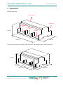
1
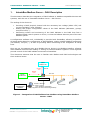
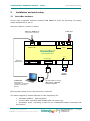
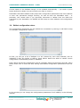
IntesisBox® Modbus Server DALI User's manual Issue Date: 2011/07/20 r0 eng IntesisBox® Modbus Server - DALI © Intesis Software S.L. User’s Manual r0 eng All Rights Reserved. Information in this document is subject to change without notice. The software described in this document is furnished under a license agreement or nondisclosure agreement. The software may be used only in accordance with the terms of those agreements. No part of this publication may be reproduced, stored in a retrieval system or transmitted in any form or any means electronic or mechanical, including photocopying and recording for any purpose other than the purchaser’s personal use without the written permission of Intesis Software S.L. Intesis Software S.L. Milà i Fontanals, 1 bis - 1º 08700 Igualada Spain TRADEMARKS All trademarks and tradenames used in this document are acknowledged to be the copyright of their respective holders. © Intesis Software S.L. - All rights reserved This information is subject to change without notice ® IntesisBox is a registered trademark of Intesis Software SL URL Email tel http://www.intesis.com [email protected] +34 938047134 2 / 23 IntesisBox® Modbus Server - DALI User’s Manual r0 eng Gateway for the integration of DALI ballast devices into Modbus control systems. Order code: IBOX-MBS-DALI © Intesis Software S.L. - All rights reserved This information is subject to change without notice ® IntesisBox is a registered trademark of Intesis Software SL URL Email tel http://www.intesis.com [email protected] +34 938047134 3 / 23 IntesisBox® Modbus Server - DALI User’s Manual r0 eng INDEX 1. IntesisBox Modbus Server – DALI Description ..................................................... 5 1.1 DALI interface ............................................................................................... 6 1.2 Modbus interface ........................................................................................... 7 2. Installation and quick-setup ............................................................................. 11 2.1 IntesisBox hardware .................................................................................... 11 2.2 Quick-setup ................................................................................................ 12 2.2.1 DALI connection setup ........................................................................... 12 2.2.2 Ethernet connection setup ...................................................................... 12 3. Editing the configuration project for DALI .......................................................... 14 3.1 IntesisBox Configuration Window .................................................................. 14 3.2 Switching from Offline to Online mode ........................................................... 14 3.3 Configuration of short addresses for DALI ballasts ........................................... 15 3.4 Ballast configuration values .......................................................................... 18 3.5 Modbus configuration ................................................................................... 20 4. Mechanical & electrical characteristics ............................................................... 22 5. Dimensions .................................................................................................... 23 © Intesis Software S.L. - All rights reserved This information is subject to change without notice ® IntesisBox is a registered trademark of Intesis Software SL URL Email tel http://www.intesis.com [email protected] +34 938047134 4 / 23 IntesisBox® Modbus Server - DALI User’s Manual r0 eng IntesisBox Modbus Server – DALI Description 1. This document describes the integration of DALI ballasts in Modbus compatible devices and systems, with the use of IntesisBox Modbus Server – DALI device. The ending of this device is: Providing a DALI physical channel with the necessary bus voltage (about 15V) and current regulation (max. 250mA). Setting the proper configuration values of the DALI ballasts (addresses, groups, max/min levels,…). Performing control and monitoring of the DALI ballasts in the DALI bus from a Modbus-based control system or device, so that the ballasts become part of the own Modbus system. A configuration software tool, LinkBoxMB, is provided with IntesisBox, allowing to perform all setup tasks related to configuration of DALI ballasts, setting needed Modbus parameters (IP address, TCP port,…) as well as providing basic monitoring of the integration at setup time. Once set up, the gateway acts as a Modbus Server device in its Modbus interface, allowing other Modbus client devices reading or writing its internal Modbus registers. These registers provide control of the DALI ballasts connected to IntesisBox. This document assumes that the user is familiar with Modbus and DALI technologies and their technical terms. Master ModBus TCP Modbus TCP Ethernet Modbus RTU Master ModBus RTU DALI bus RS232/RS485 IntesisBox EIA232 or Ethernet LinkBoxMB Configuration Software DALI ballasts Only needed for configuration (configuration can also be done using Ethernet) Figure 1 - Integration of DALI ballasts into Modbus using IntesisBox Modbus Server - DALI © Intesis Software S.L. - All rights reserved This information is subject to change without notice ® IntesisBox is a registered trademark of Intesis Software SL URL Email tel http://www.intesis.com [email protected] +34 938047134 5 / 23 IntesisBox® Modbus Server - DALI 1.1 User’s Manual r0 eng DALI interface DALI (Digitally Addressable Lighting Interface) is a standard defining a set of functionalities and requirements to be fulfilled by lighting ballasts. DALI ballasts communicate as well using the same protocol (DALI protocol), defined in the standard and supported by IntesisBox. From a functional point of view, DALI ballasts provide following features: Digital control of actual arc power level (dim level) o Controllable either individually, or by previously defined groups of ballasts. o Set to arbitrary power/dim levels between OFF and 100%, or previously defined “preset” levels (scenes). o Using predefined fade rates/times upon power level change. Reporting of their actual status o Mainly for detecting failure conditions of the ballast or the installation. A single DALI channel supports up to 64 ballasts, being this one the maximum number of individual ballasts that can be integrated with a single IntesisBox. The DALI channel needs a power source, which will be provided by IntesisBox itself. As per the requirements of the standard, nominal bus voltage provided by IntesisBox is 15V, and has a current limiter of 240/250mA. Each DALI ballast has an own permanent storage memory, where it stores its own configuration values. These values can be read, set and changed using IntesisBox at setup time. They are the following: Short Address (Individual address / Address for individual control) Random Address (Unique address providing a way of addressing a ballast without assigned individual/short address) Physical Minimum Level (read-only/defined by ballast manufacturer) Minimum Level Maximum Level Power-on Level System Failure Level Fade Rate Fade Time Group membership (a DALI channel can have up to 16 groups and each ballast can belong to any number of them at the same time) Level for scene 0…15 (up to 16 scenes/preset dim levels can be configured within each ballast) Configuration of all ballast parameters can be done with IntesisBox, using LinkBoxMB software configuration tool. Usage of this tool is explained in detail in the LinkBoxMB User’s Manual. Information on DALI technology and a list of existing ballast manufacturers can be found at AG DALI association’s website (www.dali-ag.org). © Intesis Software S.L. - All rights reserved This information is subject to change without notice ® IntesisBox is a registered trademark of Intesis Software SL URL Email tel http://www.intesis.com [email protected] +34 938047134 6 / 23 IntesisBox® Modbus Server - DALI 1.2 User’s Manual r0 eng Modbus interface DALI ballasts connected to IntesisBox are accessible by means of its Modbus server interface. Each DALI ballast is abstracted at Modbus side as a set of Modbus registers. The value they represent is always accessed in IntesisBox by means of its Modbus register. ModBus functions 03 or 04 (read holding registers and read input registers) must be used to read Modbus registers. ModBus function 06 (Single Multiple Holding Registers) must be used to write Modbus registers. If poll records are used to read or write more than one register, it is necessary that the range of addresses requested contains valid addresses, if not the corresponding ModBus error code will be returned. All the registers are of 16 bit, and its content is expressed in MSB..LSB. ModBus error codes are fully supported, they will be sent whenever a not valid Modbus action or address is required. © Intesis Software S.L. - All rights reserved This information is subject to change without notice ® IntesisBox is a registered trademark of Intesis Software SL URL Email tel http://www.intesis.com [email protected] +34 938047134 7 / 23 IntesisBox® Modbus Server - DALI User’s Manual r0 eng For each ballast, following is the list of its related Modbus registers: Point name Dali Dxx Sts Description Byte value representing ballast xx status b7…b0 o Dali Dxx PwrSet Dali Dxx Cmd 0% (off) … 100% / MAX level Requested arc power level on ballast xx 0% (off) … 100% / MAX level Requested command on ballast xx (4*xx)+6 RW (4*xx)+7 RW (4*xx)+8 0: No arc power ctrl command received after power-up 1: Arc power control command received after power-up Current arc power level reported by ballast xx R 0: Short address is programmed 1: Missing short address Bit b7: Power failure o o Dali Dxx PwrLvl 0: No reset state 1: Reset state (factory configuration values in ballast) Bit b6: Missing short address o o 0: No fade is running (fade is ready) 1: Fade is running Bit b5: Reset state o o 0: Last requested arc power cmd between MIN and MAX level (or OFF) 1: Last requested arc power cmd is out of MIN/MAX level range Bit b4: Fade running o o 0: Lamp is OFF 1: Lamp is ON Bit b3: Limit error o 0: Lamp is OK 1: Lamp is in failure Bit b2: Lamp arc power on o o 0: Ballast is OK 1: Ballast is in failure Bit b1: Lamp failure o o Point # (4*xx)+5 Bit b0: Ballast failure o o Signal R 0 – Set Arc Power Off 1 – Arc Power 100% 2 – Step Up 3 – Step Down 10 – Set Minimum Arc Power Level1 11 – Set Maximum Arc Power Level1 1yy – Go to Scene yy 2yy – Store Current Level as Scene yy1 3yy – Clear/Remove Scene yy1 1yyy – Set Fade Rate to yyy (steps/second) 1 2yyy – Set Fade Time to yyy (seconds) 1 3yyy – Set Min Level Rate to yyy (in %)1 4yyy – Set Max Level Time to yyy (in %)1 5yyy – Set Power-on Level Time to yyy (in %)1 6yyy – Set System-failure Level to yyy (in %)1 1 This command will overwrite ballast’s permanent storage memory. Permanent storage memories have a limited rated number of writes. Therefore, intensive/repetitive use of this command will harm your ballast’s permanent storage memory. In the list, value xx poses as the ballast short/individual address, and takes value 0 to 63. The Point # is the modbus register number. © Intesis Software S.L. - All rights reserved This information is subject to change without notice ® IntesisBox is a registered trademark of Intesis Software SL URL Email tel http://www.intesis.com [email protected] +34 938047134 8 / 23 IntesisBox® Modbus Server - DALI User’s Manual r0 eng Additionally, IntesisBox implements two registers allowing group-based control of ballasts. See following list: Point name Dali Gxx PwrSet Description Requested arc power level on group xx Dali Gxx Cmd 0% (off) … 100% / MAX level Signal Point # RW 261 + (xx*2) RW 262 + (xx*2) Requested command on group xx 0 – Set Arc Power Off 1 – Arc Power 100% 2 – Step Up 3 – Step Down 10 – Set Minimum Arc Power Level2 11 – Set Maximum Arc Power Level2 1yy – Go to Scene yy 2yy – Store Current Level as Scene yy2 3yy – Clear/Remove Scene yy2 1yyy – Set Fade Rate to yyy (steps/second) 2 2yyy – Set Fade Time to yyy (seconds) 2 3yyy – Set Min Level Rate to yyy (in %)2 4yyy – Set Max Level Time to yyy (in %)2 5yyy – Set Power-on Level Time to yyy (in %)2 6yyy – Set System-failure Level to yyy (in %)2 In the list, value xx poses as the group number being controlled, and takes value 0 to 15. Additionally, IntesisBox implements two registers allowing broadcast control of all ballasts together. See following list: Point name Dali All PwrSet Description Requested arc power level to all ballasts Point name Dali All Cmd 0% (off) … 100% / MAX level Description Requested command to all ballasts 0 – Set Arc Power Off 1 – Arc Power 100% 2 – Step Up 3 – Step Down 10 – Set Minimum Arc Power Level1 11 – Set Maximum Arc Power Level1 1yy – Go to Scene yy 2yy – Store Current Level as Scene yy1 3yy – Clear/Remove Scene yy1 1yyy – Set Fade Rate to yyy (steps/second) 1 2yyy – Set Fade Time to yyy (seconds)1 3yyy – Set Min Level Rate to yyy (in %)1 4yyy – Set Max Level Time to yyy (in %)1 5yyy – Set Power-on Level Time to yyy (in %)1 6yyy – Set System-failure Level to yyy (in %)1 Signal Point # RW 293 Signal Point # RW 294 1 This command will overwrite ballast’s permanent storage memory. Permanent storage memories have a limited rated number of writes. Therefore, intensive/repetitive use of this command will harm your ballast’s permanent storage memory. © Intesis Software S.L. - All rights reserved This information is subject to change without notice ® IntesisBox is a registered trademark of Intesis Software SL URL Email tel http://www.intesis.com [email protected] +34 938047134 9 / 23 IntesisBox® Modbus Server - DALI User’s Manual r0 eng Finally, there is a set of 4 registers reporting, in a compact way, a faulty status of each ballast in the line. Point name Dali Err D15-00 Description 2 byte value b15…b0 representing status of ballasts with individual/short addresses 0 to 15, in the following way: Bit b0: Status of ballast 0 o 0: Ballast OK o 1: Ballast not present in bus, ballast failure , lamp failure or not configured in database Dali Err D31-16 Bit b1: Status of ballast 1 … Bit b15: Status of ballast 15 2 byte value b15…b0 representing status of ballasts with individual/short addresses 16 to 31. Signal Point # R 1 R 2 R 3 R 4 (b0 relates to ballast 16, b1 to ballast 17, …, b7 to ballast 31) Dali Err D47-32 2 byte value b15…b0 representing status of ballasts with individual/short addresses 32 to 47. (b0 relates to ballast 32, b1 to ballast 33, …, b7 to ballast 47) Dali Err D63-48 2 byte value b15…b0 representing status of ballasts with individual/short addresses 48 to 63. (b0 relates to ballast 48, b1 to ballast 49, …, b7 to ballast 63) © Intesis Software S.L. - All rights reserved This information is subject to change without notice ® IntesisBox is a registered trademark of Intesis Software SL URL Email tel http://www.intesis.com [email protected] +34 938047134 10 / 23 IntesisBox® Modbus Server - DALI 2. 2.1 User’s Manual r0 eng Installation and quick-setup IntesisBox hardware Device uses a standard enclosure allowing DIN EN60715 TH35 rail mounting. Its plastic meets standard PC UL 94 V0. Sizes are 159mm x 105mm x 58mm. Ethernet / Modbus IP DALI Bus (and IntesisBox configuration) - ETH (Modbus IP) + DALI IntesisBox® www.intesis.com POWER 230VAC 6W N L PC Console Serial Port (Modbus RTU) EIA485 EIA232 Power 230Vac LinkBoxMB Only needed for configuration, configuration can also be done using Ethernet Console cable 1.8 m long. DB9 Female - DB9 Male standard. Supplied. Ensure proper space for all connectors when mounted. The items supplied by Intesis Software for this integration are: IntesisBox Modbus – DALI hardware Console cable. Standard DB9F-DB9M cable 1.8 meter long. Installation sheet, containing a hard-link for LinkBoxMB software download and this manual. © Intesis Software S.L. - All rights reserved This information is subject to change without notice ® IntesisBox is a registered trademark of Intesis Software SL URL Email tel http://www.intesis.com [email protected] +34 938047134 11 / 23 IntesisBox® Modbus Server - DALI 2.2 User’s Manual r0 eng Quick-setup Mount IntesisBox in the desired location (follow instructions and recommendations in its installation sheet). Next sections detail preliminary checks to perform to ensure DALI and Ethernet connectivity. 2.2.1 DALI connection setup Connect + and – terminals of the DALI bus of your ballasts to IntesisBox’ DALI port. Bus does have polarity, though most DALI ballasts are polarity insensitive. Having your DALI ballasts powered up, you can perform a quick three-step DALI connectivity test by pressing DALI test button, at the left side of its connector on IntesisBox: 1. Pressing the button once will set your ballasts to their configured maximum arc power level. DALI test red LED next to the button will start blinking, as a way of indicating that the test has started. 2. Pressing again the button will set your ballasts OFF. DALI test LED will remain steadily ON during this stage of the test. 3. And pressing again the button will end up the test, switching DALI test LED steadily OFF and leaving your ballasts at their maximum configured arc power level. If the button is not pressed during 30s, the test will move on to the next step, until the final step is reached (step 3 above). While performing this test, IntesisBox will not execute any DALI command that may have been requested from its Modbus interface. 2.2.2 Ethernet connection setup Although it is not necessary, you may want to check connectivity of your PC against the IntesisBox by means of Ethernet. This will allow you to: Configure IntesisBox using LinkBoxMB tool. Access Modbus server registers from a Modbus client in your PC (Modbus client software is not provided with the device) IntesisBox comes from factory with configured IP address 192.168.100.246. LinkBoxMB software tool allows for changing it to the one that suits your Ethernet network configuration, while being connected to IntesisBox – by either the PC Console serial port or the Ethernet / TCP/IP connection itself. If you need to setup a different IP address before connecting the IntesisBox to the Ethernet network, just read the LinkBoxMB User’s Manual and you will find a proper explanation on how to do it. © Intesis Software S.L. - All rights reserved This information is subject to change without notice ® IntesisBox is a registered trademark of Intesis Software SL URL Email tel http://www.intesis.com [email protected] +34 938047134 12 / 23 IntesisBox® Modbus Server - DALI User’s Manual r0 eng In order to setup Ethernet connection of your PC and the IntesisBox, first connect suitable Ethernet cable to IntesisBox: Use a crossover Ethernet cable if you are connecting your PC’s Ethernet adapter directly to the IntesisBox. Or use a straight Ethernet cable if you are to connect to the IntesisBox through a hub or switch in your LAN. If the IP address of your PC is in the subnet 192.168.100.* you are ready to communicate with IntesisBox. If your PC has an IP address in a different subnet, you will need to add a route in Windows routing table, by doing following: Choose “Start->Run…” and enter: cmd.exe This will open up a Windows console shell, with which you can add the route to the IntesisBox with following command line: route add 192.168.100.246 %COMPUTERNAME% In Windows Vista and Windows 7 you will need to run that command from a console shell with administration privileges. Also in these systems, you may have trouble using environment variable %COMPUTERNAME%. If this is your case, try issuing the same command changing %COMPUTERNAME% for the IP of your PC (you can get the IP from your computer with shell command ipconfig). Finally, ping 192.168.100.246 from the command shell so to check that your PC can see IntesisBox in the network: C:\>ping 192.168.100.246 Pinging 192.168.100.246 with 32 bytes of data: Reply Reply Reply Reply from from from from 192.168.100.246: 192.168.100.246: 192.168.100.246: 192.168.100.246: bytes=32 bytes=32 bytes=32 bytes=32 time<1ms time<1ms time<1ms time=1ms TTL=255 TTL=255 TTL=255 TTL=255 Ping statistics for 192.168.100.246: Packets: Sent = 4, Received = 4, Lost = 0 (0% loss), Approximate round trip times in milli-seconds: Minimum = 0ms, Maximum = 1ms, Average = 0ms © Intesis Software S.L. - All rights reserved This information is subject to change without notice ® IntesisBox is a registered trademark of Intesis Software SL URL Email tel http://www.intesis.com [email protected] +34 938047134 13 / 23 IntesisBox® Modbus Server - DALI 3. User’s Manual r0 eng Editing the configuration project for DALI 3.1 IntesisBox Configuration Window Back into LinkBoxMB main’s window, select menu option Configuration->IntesisBox… access IntesisBox configuration editor window. to There are three tabs in the configuration window: ModBus: Relates to configuration of IntesisBox parameters for its ModBus TCP/RTU interface. DALI Devices: Used for the commissioning/setup of the individual/short addresses of the DALI ballasts in the bus DALI Config: It is used for the management of the set of configuration values of each ballast (min/max level, fade rate/time, group membership, …) In following sections their usage is explained. 3.2 Switching from Offline to Online mode At this point you might want to change LinkBoxMB working mode to online – i.e. having a working link between LinkBoxMB and IntesisBox. This will allow you to exchange configuration values with the device, as you edit them. In order to do so, select menu option Configuration->Connection…. a small window showing the connection parameters will appear. © Intesis Software S.L. - All rights reserved This information is subject to change without notice ® IntesisBox is a registered trademark of Intesis Software SL URL Email tel http://www.intesis.com [email protected] +34 938047134 14 / 23 IntesisBox® Modbus Server - DALI User’s Manual r0 eng In it, you can select the communication parameters of the physical link with IntesisBox, using either a Modbus RTU EIA232/485 connection or a Modbus TCP (Ethernet) connection. For Ethernet, default/factory value of the IP configured on 192.168.100.246. TCP Port is always 23 and shouldn’t be changed. IntesisBox is always Once done setting up suitable parameters, click Save. Now, to switch LinkBoxMB to Online mode, click on the Connect button in the upper left part of the main window. Upon successful connection, status will change to Online with a green picture. By doing that, some text will appear in the IntesisBox Communication Console window as shown in the picture above. This window always shows the (ASCII-based) communication between LinkBoxMB and IntesisBox. At the moment, it shows information on the firmware version loaded on IntesisBox and its configuration status. Later on, when done with your configuration work using LinkBoxMB, and leaving your IntesisBox device “stand-alone” in the installation it’s specially important that you remember switching off the gateway by clicking the Connect button before disconnecting the physical cable (Ethernet or EIA232/485) from IntesisBox – otherwise, IntesisBox would remain unnecessarily in the “Online” status, trying to report debugging and configuration information to a non-existing connected PC. Additionally, in case of using a USB-EIA232 converter, unplugging the USB converter before switching off the LinkBoxMB, may crash your system forcing you to reboot your computer. 3.3 Configuration of short addresses for DALI ballasts First step to do for proper configuration, is detecting the ballasts present in your DALI bus, and assigning them with an individual/short address. To do so, being in mode Online and with IntesisBox DALI configuration window, select tab DALI devices. Configuration window will look like the shot shown below. © Intesis Software S.L. - All rights reserved This information is subject to change without notice ® IntesisBox is a registered trademark of Intesis Software SL URL Email tel http://www.intesis.com [email protected] +34 938047134 15 / 23 IntesisBox® Modbus Server - DALI User’s Manual r0 eng You will use it to scan existing DALI ballasts in your installation, and once found, assign them with a short address. First, press button Scan in the right part of the window. It will start the process of ballast scanning in the DALI bus, which will take from some seconds up to several minutes (2 or 3 minutes at most), depending on the number of ballasts in your installation. Once scan is finished, a set of ballasts and their current address will appear in the list of Scanned Devices. The figure below shows the result of scanning a DALI bus with one ballast. There is a field telling the Random Address of each ballast, which is a unique identifier in the bus for them, and another field telling their Short Address. It is possible and likely that your ballasts at the time have no assigned short address – in this case the Short Address field in the list will appear empty (like in the shot above). Now you should assign a short address (ranging 0 to 63) to each of the ballasts that have been discovered in the bus. Before that, you might want to identify the physical location of each ballast, so to assign a short address based on its location in the installation. In order to be able to physically identify each ballast, select it from the list and press button Wink. Wink operation will send suitable DALI commands on the bus to force a change between minimum and maximum arc power level of the ballast for some seconds, so that you can find it. Once identified and decided which address you want to assign to a particular ballast, select it from the list of scanned ballasts and fill in fields Short and Device name in the right part © Intesis Software S.L. - All rights reserved This information is subject to change without notice ® IntesisBox is a registered trademark of Intesis Software SL URL Email tel http://www.intesis.com [email protected] +34 938047134 16 / 23 IntesisBox® Modbus Server - DALI User’s Manual r0 eng of the window (text boxes in the right part of Scanned Devices list). Short stands for short/individual address, and should be a number between 0 and 63. Device name can be any name that is meaningful to you to identify this ballast later on. Finally, press button Add to DB to add the ballast to the ballast database. This will make the ballast disappear from the list of scanned ballasts and appear in the list Devices in Database, like shown below. The ballast database is the list of ballasts with assigned short address that IntesisBox continuously monitors for checking their status. Proceed to add the remaining scanned ballasts until you have them all added into the database. Keep in mind that short addresses assigned to each of the ballasts in the channel must be unique. Once you have a ballast in the database, you can perform following operations, using their corresponding buttons: Change its short address (by using proper text box and button under label Set, next to the Devices in database list). Change the name for identifying it (also by using proper text box and button under label Set, next to the Devices in database list). Wink it, in order to test it or locate it physically. Delete it from the database – this will remove ballasts’ short address from the database, and the ballast will appear in the list of Scanned Devices over again. Delete All ballasts from database – same as previous option, but for all ballasts in the database. Refresh the database. This option retrieves the database from a working IntesisBox you have just connected LinkBoxMB to, so to know the list of addressed ballasts it is monitoring. After adding ballasts into the database, or Refreshing the database itself, you will also get feedback on the current communication status of the ballast: Ballast is Online when IntesisBox detects it in the bus (i.e., ballast answers DALI poll requests triggered from IntesisBox). Shown also by icon in field for short address. Ballast is Offline when IntesisBox does not detect it in the bus (i.e., ballast does not answer DALI poll requests triggered from IntesisBox). Shown also by icon in field for short address. © Intesis Software S.L. - All rights reserved This information is subject to change without notice ® IntesisBox is a registered trademark of Intesis Software SL URL Email tel http://www.intesis.com [email protected] +34 938047134 17 / 23 IntesisBox® Modbus Server - DALI User’s Manual r0 eng Current status of the ballasts though, is not updated automatically – you need to press button Refresh to obtain it at the moment you want to check it. Remember that DALI ballasts locally keep their configuration parameters and short address in their own permanent storage memory, as well as does the IntesisBox itself – in particular, this means that if you physically disconnect a ballast from the DALI bus controlled by the IntesisBox, the ballast will still keep its short address and configuration values. 3.4 Ballast configuration values The configuration parameters for the ballasts are accessible by clicking on tab DALI Config in IntesisBox Configuration window. At first, you will get a list of ballasts 0 to 63 (ordered by their short address) and an indication if they are Online or Offline. Press button Read from DALI to obtain current configuration of all ballasts present in database. Figure above shows the configuration grid as it appears when first accessing this tab, figure below shows how it looks like after having read ballast configuration parameters from the bus. In this window you can change the configuration parameters for all ballasts, in the following manner: © Intesis Software S.L. - All rights reserved This information is subject to change without notice ® IntesisBox is a registered trademark of Intesis Software SL URL Email tel http://www.intesis.com [email protected] +34 938047134 18 / 23 IntesisBox® Modbus Server - DALI User’s Manual r0 eng Change its minimum arc power level (MinLv), maximum arc power level (MaxLv), power-on level (PonLv) or system-failure level (SflLv) by double clicking its corresponding text box and editing its value. Place a value between ballast’s physical minimum level (PhyMinLv) and 100%. Change its fade rate or fade time by right clicking its corresponding cell and selecting the value from the contextual menu. Add or remove the ballast from one of the 16 possible groups (values G0 to G15) by right-clicking the corresponding cell and selecting the group number. It’s also possible to change group membership by simply double-clicking the cell corresponding to the group you want the ballast to be added to/removed from. Change the level for each of the 16 possible scenes of the ballast by double clicking its corresponding text box S0 to S15, and entering a value between ballast’s physical minimum level (PhyMinLv) and maximum arc power level (MaxLv). Leave this cell empty if you don’t want the ballast to have an assigned value for a particular scene S0 to S15 (default). Change of a certain parameter value for several ballasts at the same time is possible, by selecting multiple cells under the same title – use shift-holding selection or keep mouse button pressed while moving the mouse through all the rows you want to change. Then right-click the selection and change the value from the contextual menu. Physical minimum level of a ballast is the minimum dim level that the ballast is able to be dimmed to, as per its design. This value is defined by its manufacturer and cannot be changed. Once done with the changes, they need to be sent to the bus. I.e., the configuration will not take effect until ballasts in the installation are effectively programmed with the chosen values. To do so, click button Save to DALI. This will send all configuration values to each of the ballasts, so that they keep their values in their own permanent storage memory. At this point, configuration of the ballasts can and should be saved to the project, by pressing button Save to PC. This will update local file DALI.dat of your project on hard-disk, keeping a record of the configuration you have just edited or sent to the ballasts. Note that you can edit any of the rows in this window, even if its corresponding ballast is not present in IntesisBox’ database. This is so, so that you can edit a whole configuration for the ballasts without being in the installation/being not connected in LinkBoxMB. Thus, being connected or not, you can press buttons Save to PC and Read from PC to store and recover a configuration from your project folder. © Intesis Software S.L. - All rights reserved This information is subject to change without notice ® IntesisBox is a registered trademark of Intesis Software SL URL Email tel http://www.intesis.com [email protected] +34 938047134 19 / 23 IntesisBox® Modbus Server - DALI 3.5 User’s Manual r0 eng Modbus configuration Modbus TCP and RTU configuration parameters are accessed in tab Modbus of IntesisBox Configuration window. If Modbus TCP is selected, then: IP address of IntesisBox at its Ethernet port, which will be used for both Modbus TCP and LinkBoxMB access to the device. Default is 192.168.100.246. NetMask indicating the IP address range. Default is 255.255.255.0. Default gateway of your IP network. Is left empty by default. TCP port that will be used for Modbus TCP. Default is 502. Timeout Keep Alive: Enter the Keep Alive Timeout (in seconds). This is the time without Modbus TCP traffic after which IntesisBox will send a Keep Alive packet to the master(s) connected to it, this is to maintain alive the TCP. Default is 30s. Update present value on fading check: o If this check-box is enabled, Modbus signal DALI PwrLvl for each installed ballast will be always updated (even while the ballast is fading its own arc power level value). In section 1.2 you can find a the list of Modbus registers associated to each ballast. o If this check-box is not enabled, Modbus signal DALI PwrLvl will not be updated for a ballast that is performing a fading (i.e., arc power value will only be shown when the ballast is not fading). In section 1.2 you can find a the list of Modbus registers associated to each ballast. Once you have changed these parameters, you can and send them to IntesisBox with the button Send to GW, and/or store them in your PC (in project’s folder) using button Save to file. Take into account that, if you change the IP parameters of the IntesisBox, and you are holding an Ethernet/IP connection with it for communicating with LinkBoxMB, you will need to update LinkBoxMB’s connection parameters to match accordingly (see section 3.2). If Modbus RTU RS232/485 is selected, then: Connection: Select the port to use (RS232 or RS485). Baud rate: Select the baud rate to use. Parity: Select the parity. Slave: Enter the Modbus slave number for IntesisBox. © Intesis Software S.L. - All rights reserved This information is subject to change without notice ® IntesisBox is a registered trademark of Intesis Software SL URL Email tel http://www.intesis.com [email protected] +34 938047134 20 / 23 IntesisBox® Modbus Server - DALI User’s Manual r0 eng If Modbus TCP + Modbus RTU is selected, then: Both Modbus TCP and Modbus RTU connections will be active with the parameters configured on each of them. You can also read the actual configuration for these parameters in IntesisBox using button Read from GW, or read your currently stored project configuration (from file DALI.ini in project folder) using button Read from file. © Intesis Software S.L. - All rights reserved This information is subject to change without notice ® IntesisBox is a registered trademark of Intesis Software SL URL Email tel http://www.intesis.com [email protected] +34 938047134 21 / 23 IntesisBox® Modbus Server - DALI 4. User’s Manual r0 eng Mechanical & electrical characteristics Enclosure DALI bus power source Plastic, type PC (UL 94 V-0). Dimensions: 159mm 105mm x 58mm. Light Grey / RAL 7035. 230Vac +/-10% 6W (3-pole plug-in terminal block – line, neutral and earth) Wall. DIN rail EN60715 TH35. 15Vdc +/-2% 250mA. (DALI bus is powered from IntesisBox) DALI port 1 x DALI electrically isolated (2-pole plug-in terminal block). Color Supply Voltage Mounting Ethernet port 1 x Ethernet 10BT RJ45. (Modbus IP, device config) Modbus RTU ports 1 x Serial RS232 (DB9 male DTE). 1 x Serial RS485 (Plug-in screw terminal block, 2 poles). LED indicators 1 x Power indicator. 2 x DALI activity (Tx, Rx). 2 x Ethernet link & activity (LNK, ACT). 2 x Modbus RTU port activity (Tx, Rx). 1 x DALI bus power 1 x DALI test1 Push buttons 1 x DALI test1 Console port EIA232. DB9 female connector (DCE). Configuration Via Ethernet or serial console port.2 Firmware Allows upgrades via console port. Operational 0°C to +60°C temperature Operational 25-90% at 50ºC, non condensing humidity Protection IP20 (IEC60529). RoHS conformity Compliant with RoHS directive (2002/95/CE). Certifications CE 1 DALI test push-button and LED are meant to perform a quick test of your DALI line and connected ballasts. 2 Standard cable DB9 male-DB9 female 1,8 meters long is supplied with the device for connection to a PC COM port for configuring and monitoring the device using the serial port (Ethernet is also possible). The configuration software, compatible with Windows® operating systems, is also supplied. © Intesis Software S.L. - All rights reserved This information is subject to change without notice ® IntesisBox is a registered trademark of Intesis Software SL URL Email tel http://www.intesis.com [email protected] +34 938047134 22 / 23 IntesisBox® Modbus Server - DALI User’s Manual r0 eng 5. Dimensions External dimensions Ethernet port DALI port Serial RS485 port Serial console port 58 mm AC mains power 159 mm 105 mm Free space recommended in the install location of the device, with spacing enough for external connections. 100 mm 130 mm 167 mm © Intesis Software S.L. - All rights reserved This information is subject to change without notice ® IntesisBox is a registered trademark of Intesis Software SL URL Email tel http://www.intesis.com [email protected] +34 938047134 23 / 23