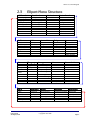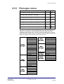
1
EXpert
EXkeypad Stand
Alone Programmer
(5002-2070)
User Manual
UM0090.GB Issue 3 26/08/2015
www.tdsi.co.uk
TDSi
Unit 10 Concept Park
Innovation Close
Poole
Dorset
BH12 4QT, UK
Tel: +44 (0) 1202 723535
Fax: +44 (0) 1202 724975
Sales Enquiries:
Marketing Support:
Technical Support:
[email protected]
[email protected]
[email protected]
Foreword
Copyright © 2002 TDSi. All rights reserved.
Time and Data Systems International Ltd operate a policy of continuous
improvement and reserves the right to change specifications, colours or
prices of any of its products without prior notice.
Guarantee
Guarantee
For terms of guarantee, please contact your supplier.
Trademarks
Copyright © 2002 Time and Data Systems International Ltd (TDSi). This
document or any software supplied with it may not be used for any purpose
other than that for which it is supplied nor shall any part of it be reproduced
without the prior written consent of TDSi.
Microsoft and Windows are registered trademarks of Microsoft Corporation.
All other brands and product names are trademarks or registered
trademarks of their respective owners.
Cautions and Notes
The following symbols are used in this guide:
CAUTION! This indicates an important operating instruction that
should be followed to avoid any potential damage to hardware or
property, loss of data, or personal injury.
NOTE. This indicates important information to help you make the best use
of this product.
Table of Contents
1.
Introduction................................
Introduction ................................................................
................................................................................................
...........................................................................................
........................................................... 1
1.1
2.
How to use this manual ................................................................................................................................. 1
How to use the EXkeypad ................................................................
................................................................................................
................................................................ 2
2.1
Key functions ..................................................................................................................................................... 2
2.2
Starting programming - Going into the Main Menu Map .................................................................... 3
2.3
EXpert Menu Structure ................................................................................................................................... 5
3.
Overview of menu features ................................................................
.............................................................................................
............................................................. 6
3.1
ACU Functions menu ....................................................................................................................................... 6
3.2
Door Functions menu ...................................................................................................................................... 6
3.3
Lift Functions menu......................................................................................................................................... 7
3.4
Reader Functions menu ................................................................................................................................. 7
3.5
Validate menu .................................................................................................................................................... 9
3.5.2
Forgive ID........................................................................................................................................... 9
3.6
Void menu ........................................................................................................................................................... 9
3.7
Access Modes menu ........................................................................................................................................ 9
3.8
Counters menu ................................................................................................................................................ 10
3.9
Time groups menu.......................................................................................................................................... 10
3.10 Messages menu............................................................................................................................................... 10
3.11 Printouts menu ................................................................................................................................................ 10
3.12 Communications menu ................................................................................................................................. 11
3.13 Clock menu ........................................................................................................................................................ 11
3.14 Holidays.............................................................................................................................................................. 11
3.15 Diagnostics menu ........................................................................................................................................... 11
3.16 Resets menu..................................................................................................................................................... 11
3.17 Password menu ............................................................................................................................................... 11
3.18 Unit Control menu .......................................................................................................................................... 11
4.
Reference Section ................................................................
................................................................................................
.............................................................................
............................................. 12
4.1
ACU Functions menu ..................................................................................................................................... 12
4.2
Door Functions menu .................................................................................................................................... 15
4.3
Reader Functions menu ............................................................................................................................... 19
4.4
Validate menu .................................................................................................................................................. 25
4.5
Void menu ......................................................................................................................................................... 28
Last Change
26 August, 2015
EXkeypad User Manual
Copyright © 2002 TDSi
Page i
4.6
Access Modes menu ...................................................................................................................................... 29
4.7
Relays menu ..................................................................................................................................................... 32
4.7.1
Control options .............................................................................................................................. 33
4.7.2
Program options ............................................................................................................................ 33
4.7.3
Holidays ............................................................................................................................................ 35
4.7.4
Hold-on time ................................................................................................................................... 35
4.7.5
Control Card..................................................................................................................................... 35
4.8
Inputs menu ...................................................................................................................................................... 36
4.8.1
Application....................................................................................................................................... 36
4.8.2
On delay/Off delay ....................................................................................................................... 38
4.8.3
Use ..................................................................................................................................................... 38
4.8.4
Up counter/ Down counter ........................................................................................................ 38
4.9
Counters menu ................................................................................................................................................ 39
4.10 Timegroups menu ........................................................................................................................................... 40
4.10.2 Control............................................................................................................................................... 42
4.10.3 Program ............................................................................................................................................ 42
4.10.4 Holidays ............................................................................................................................................ 42
4.10.5 Control Card..................................................................................................................................... 42
4.11 Messages menu............................................................................................................................................... 43
4.12 Printouts menu ................................................................................................................................................ 44
4.13 Communications menu ................................................................................................................................. 44
4.13.1 Unit number .................................................................................................................................... 45
4.13.2 Mode .................................................................................................................................................. 45
4.14 Clock menu ........................................................................................................................................................ 46
4.15 Diagnostics menu .......................................................................................................................................... 46
4.15.1 Input Test ........................................................................................................................................ 46
4.15.2 Relay Test........................................................................................................................................ 47
4.15.3 RAM Test.......................................................................................................................................... 47
4.15.4 ROM CRC ........................................................................................................................................... 47
4.15.5 Comms test ..................................................................................................................................... 47
4.16 Resets menu..................................................................................................................................................... 48
4.16.1 Warm restart ................................................................................................................................... 48
4.16.2 Erase id store .................................................................................................................................. 48
4.16.3 Erase events ................................................................................................................................... 48
4.16.4 Reset parameters ......................................................................................................................... 48
4.16.5 System reset................................................................................................................................... 48
4.17 Password menu ............................................................................................................................................... 49
4.18 Unit Control menu .......................................................................................................................................... 51
4.18.1 Reset unit ........................................................................................................................................ 51
4.18.2 Unit info............................................................................................................................................ 51
4.18.3 Identify unit .................................................................................................................................... 51
EXkeypad User Manual
Copyright © 2002 TDSi
Page ii
Last Change
26 August, 2015
4.18.4
4.18.5
4.18.6
5.
UID - Unit................................................................................................................................. 51
Change unit ..................................................................................................................................... 51
Number of units............................................................................................................................. 52
EXkeypad Messages ................................................................
................................................................................................
.........................................................................
......................................... 53
Last Change
26 August, 2015
EXkeypad User Manual
Copyright © 2002 TDSi
Page v
This page intentionally left blank
1. Introduction
1.1
How to use this manual
This manual gives details on the programming of EXpert access control
units (ACU’s) using the EXkeypad programmer.
This Introduction section contains the following:
A description of how to use the EXkeypad
A MENU 'map' of how the programming menus are arranged.
The Overview section contains a brief description of every option that can
be programmed in an EXpert 2 access control unit (ACU)
The Reference section contains details of each feature.
Both the Overview and Reference sections present the features in the same
order that they appear in the EXpert menu. The Index section lists them
alphabetically.
Last Change
26 August, 2015
EXkeypad User Manual
Copyright © 2002 TDSi
Page 1
2. How to use the EXkeypad
2.1
Key functions
Number
keys
Up /Down
arrows
Left &
Right
arrows
# Key
* Key
These are used to enter numerical data.
Below the number keys are the letters of the alphabet.
These keys are used to enter letters when adding names
to cards
These are used to scroll through the list of menu options
in either direction.
Sometimes, instead of typing in values, the up/down
arrows can be used to increase/decrease the number
shown on the display.
These are used to position the cursor to enter data, and
make corrections when entering data.
This is the Quit key. Pressing this key partway through
any programming operation cancels the current action. In
most cases the user is taken back up one menu level,
and any data entered has been cancelled.
This is the Execute or Enter key. Pressing this key will
either open the displayed menu item, or accept the data
on the display and store it in memory.
When you first plug in the EXkeypad, or if you power up the ACU with it
already connected you will get the default display:
Which provides some useful Functions –
These are then available before going into the Main menu
On default screen location:
EXpert
TDSi Ltd
16:17
Press Up arrow or Down arrow:
Gives the events: – upper most event = the last event
Firmware Version
Press # and you get the firmware version:
EXpert
10:37
V*
V *.*-**
R Jun 17
UID Number
Press # then Up arrow to get the UID number of the Expert master
Last Change
26 August, 2015
EXkeypad User Manual
Copyright © 2002 TDSi
Page 2
How to use the EXkeypad
2.2
Starting
Starting programming - Going
into the Main Menu Map
Programming is password-protected – press any key and you get a request
for
PIN:
Enter the password (the default is 1234) and press the enter (*) key. If it is
more than 10 minutes since the EXkeypad was used for programming, then
it will have “timed out” of programming mode, back into normal operating
mode, with the time and date shown on the display.
Selecting a menu item
Use the UP and DOWN arrows to scroll through the various Main Menu
options. When the desired option is showing on the display, press “*” to
execute and the user is taken into a list of sub menu’s for that main menu
option selected.
Entering data
There are some occasions when the user can’t scroll through the options,
for example when entering card numbers or names. Simply enter the
information required and press “*” when finished. When entering names the
user will be required to press the right arrow every time a letter is entered.
To make corrections, use the LEFT and RIGHT arrows to position the cursor
beneath the character or figure to be corrected. The cursor does not have to
be at the end of the line to enter data.
Deleting data
As there is no Delete key, in most cases you delete data by replacing it with
a string of zeros.
Returning to the main menu
Wherever you are in the menu system, keep pressing the Quit key (#) until
the top line shows ‘MAIN MENU’. If you press the quit key again you will
come out of the Menu Map and will need to put your password again to
enter the menu.
Selecting doors, readers, relays and inputs
Some operations require that you identify which items you wish to affect.
This means selecting one or more of all of the possibilities, and the display
looks something like this:
1234567890123456
0000000000000000
In such a display, the top row represents 16 relays (for example), numbered
1-16 but with the leading “1” left off those in the range 10-16. The second
row shows which items are selected – a 1 means selected; 0 is not selected.
Last Change
26 August, 2015
EXkeypad User Manual
Copyright © 2002 TDSi
Page 3
How to use the EXkeypad
In the case of doors and readers, the configuration will determine which
numbers are utilised; an X is used to denote any that are not used (e.g.
redundant doors in a two-reader one-door configuration). The following table
shows the numbering that applies. It is important to realise that, for example,
readers on EXpander no.7 will always be 15 and 16 even if it is the only
EXpander unit online in the system.
Type
Sub Unit No.
EXpert
0
EXpander
1
EXpander
2
EXpander
3
EXpander
4
EXpander
5
EXpander
6
EXpander
7
Door or
Reader No.
1
2
3
4
5
6
7
8
9
10
11
12
13
14
15
16
EXkeypad User Manual
Copyright © 2002 TDSi
Page 4
Last Change
26 August, 2015
How to use the EXkeypad
2.3
EXpert Menu Structure
ACU Functions
PIN-only digits
Memory options
Language
Full ID prompts?
Mode
Auto-fallback
Validate
Which reader?
Validate card
Validate PIN
Block validate
Forgive ID
ID reader
Counters
Value
Limit
Relay
Reset
Reset
value
Void
Void Id
Void PIN
Block Void
Timegroups
Control
Program
Holidays
Control card
Clock
Time
Date
Date Format
Clocks forward
Clock back
Holidays
Last Change
26 August, 2015
Door Functions
Which door?
Lock Time
Door sensor type
Ajar time (L)
Ajar time (R)
Alarm shunt off
Mantrap
DDA time
Lock drive end
Lift Functions
Which lift?
Select time
Select sense
Access Modes
Control
Program
Holidays
Control card
Reader Functions
Which reader?
Reader type
Anti-passback
Led type
Down counter
Up counter
Name
N-Card
N-Card count
N-Card time
Relays
Control
Program
Holidays
Hold-on time
Control Card
Messages
Access messages
Alarm messages
Input messages
Relay messages
Mode messages
Printouts
System
Readers
Doors/Lifts
IDs
Access modes
TG messages
Counter messages
Relays
Inputs
Time groups
Counters
Messages
Diagnostics
Input test
Relay test
Ram test
Rom CRC
Comms test
Resets
Res ets
Warm restart
Erase id store
Erase events
Reset parameters
System Reset
Inputs
Which unit?
Polarity
Type
On delay
Off delay
Use
Up counter
Down counter
Communications
Unit number
Mode
Baud rate
Parity
Flow control
Password
Change password
Multi-user mode
Modify user
Unit Control
Reset Unit
Unit info
Identify unit
UID <-----> Unit
Change unit
Number of Units
EXkeypad User Manual
Copyright © 2002 TDSi
Page 5
3. Overview of menu features
3.1
ACU Functions menu
PinPin-Only digits options
If PIN-only access is allowed, this determines how many digits are required
in the PIN.
Memory options
This determines how the available memory is to be shared between Cards,
Events and Time Control Lines (TCL’s). It also allows the choice of storing
names against cards (only needed if connected to a printer), and if so how
many characters to reserve for each name.
Language
Allows selection of the language used for on-screen prompts, and
messages printed at the printer.
Full ID prompts
It allows the user to decide in advance which card attributes are to be input
when validating a card or PIN. When the user validates cards or PINs, the
user will only be prompted for those attributes chosen. The prompts, which
can be enabled or disabled are: PIN with Card, Time Group, and Expiry.
Default is all prompts OFF.
Mode
This allows the user to set up the ACU (and each of its slave units) for the
correct number of doors and readers, or to enable Lift control.
AutoAuto-fallback options
Normally, the decision to grant access is taken by a master ACU, even
when a card is used in a reader controlled by a slave. Auto-fallback allows a
slave ACU to grant access if it loses communications with its master, for any
reason.
3.2
Door Functions menu
Lock time
This is the maximum duration that the lock release relay will be energized.
The relay is de-energized if the door opens before this time has expired.
Default is 5 seconds.
Door sensor type
This allows connection of either normally-open or normally-closed contacts.
Default is normally-closed (i.e. door open = contacts closed).
Last Change
26 August, 2015
EXkeypad User Manual
Copyright © 2002 TDSi
Page 6
Overview of menu features
Ajar local time
If the door stays open for more than the specified door ajar local time then
the DOOR AJAR (L) alarm is triggered: this may be a message to the printer
and/or a relay trigger. Default is 15 seconds.
Ajar remote time
If the door stays open for more than the specified door ajar remote time then
the DOOR AJAR (R) alarm is triggered: this may be a message to the
printer and/or a relay trigger. Default is 45 minutes.
Alarm Shunt Off
If the door stays open for more than the specified door ajar remote time then
the DOOR AJAR (R) alarm is triggered: this may be a message to the
printer and/or a relay trigger. Default is 45 minutes.
Mantrap
This can be used to prevent someone going through one door unless
another door is closed.
DDA time
This adds extra time to the standard door opening times for those persons
that have been given the DDA (Disabled Disability Allowance) option when
validating their card.
Lock Drive End
This option is used to provide a solution for those using monitored locks.
The default TDSi setting only recognises door open and door locked,
whereas a monitored lock recognised a third state of closed door but not
locked.
3.3
Lift Functions menu
This allows up to 36 floors to be controlled when an I/O board is used; each
card can be allowed access to any combination of the floors. This menu is
only accessible when the ACU is configured for elevator control.
Wiring the relays to the Button control in the lift: the
Select time is for how long the relay should fire active
Select sense is for the relay to be either normally closed or normally open
3.4
Reader Functions menu
Reader type
Allows selection of reader technology from the following: Microcard®,
Wiegand or Magnetic (If using mag-stripe swipe readers, cards can be used
in either direction through the reader). Wiegand cards may be TDSi's unique
40-bit cards or any 26-bit format.
Note that proximity readers should be set up as magnetic as this is their
data communication format.
Last Change
26 August, 2015
EXkeypad User Manual
Copyright © 2002 TDSi
Page 7
Overview of menu features
Note on Reader Type Auto-Detection
(After initial power-up, or after a system reset). If a card is presented at
a reader wired to the EXpert 2 ACU, the system will automatically set
all other readers attached to the ACU and associated EXpanders to the
same reader technology by default. The user will be required to reprogram readers with the correct technology if they are different from
the one set as default.
AntiAnti-passback
There are two types of anti-passback (APB): True and Timed. True APB
prevents a card from being used at one reader twice in succession; i.e. the
card must be used to go ‘out’ before it can be used to come ‘in’ again.
Timed APB prevents a card from being used twice within a chosen time
period (1 minute to 24 hours). A Forgiveness feature allows a ‘reset’ to be
carried out. The default setting is no anti-passback.
LED type
Some readers supplied by TDSi are single colour while others are bi-color.
EXpert will make use of bi-color LED’s to signal access granted (green) and
access denied (red) provided the correct type is selected in this menu.
Down Counter
This allows you to choose which counter (out of a possible 16) will be
decremented each time a card is granted access.
Up Counter
This allows you to choose which counter (out of a possible 16) will be
incremented each time a card is granted access.
Name
The name that will be displayed on the reader’s display. The name will also
be used instead of the reader number in Printouts and event reports.
N -Card (Multi Card Access + Multi Tap)
Tap)
This is used select which mode of Multi Card Access is required; this being
a multiple of persons required to present their access card to gain access
via a reader.
Also Multi Tap is available for Unlocking a door, for as long as required and
then Multi tap again to Lock a door back to normal Access mode. For
example a Teacher may want the classroom unlocked during the Lecture.
N -Card count
How many users are required to present their access card to gain for access
to the door.
N -card time
How long is given between for each person to present their card before the
“time out” occurs.
EXkeypad User Manual
Copyright © 2002 TDSi
Page 8
Last Change
26 August, 2015
Overview of menu features
3.5
Validate menu
Validate card
This validates a new card or edits one that is already in memory. If it is a
new card, the user will be prompted for the minimum of:
In which reader(s) the card is to be validated
The number of the card
Validate PIN
Same as ‘validate card’, but the user is prompted for a PIN instead of a card
number.
BlockBlock-validate
Validates a range of cards, all with the same time group and expiry limit,
from a start to an end number.
3.5.2
Forgive ID
You can enter the ID to remove any Anti passback enforcements to the ACU
readers.
ID Reader
Assigns a reader for use when validating cards, instead of having to type in
card numbers. This is also useful for when the card has no visible number,
or when the number read by EXpert is different from the number printed on
the card.
3.6
Void menu
Void ID
If the card is in memory, the user will be shown the reader(s) at which the
card is valid. On the bottom line of the display, a ‘1’ represents a reader
where ID is valid and an ‘X’ represents a reader where the ID is not valid.
Simply change the ‘1’ to a ‘0’ to void the ID for the specified reader.
Void PIN
Same as ‘Void ID’.
BlockBlock-void
Voids a range of cards from a start to an end number.
3.7
Access Modes menu
CardCard-Only
This is the default mode – access is granted when a card is presented at the
reader (subject to various conditions being met) without the need for a PIN.
Last Change
26 August, 2015
EXkeypad User Manual
Copyright © 2002 TDSi
Page 9
Overview of menu features
PINPIN -only
This mode allows access without a card if the reader has a keypad. The
length of the PIN can be from 4 to 8 digits. This mode can be on
permanently, or follow a schedule. The mode can also be manually enabled
and disabled using an input or a control card. A Duress function can raise
an alarm if a user is forced to open the door.
Card+PIN
This mode requires a user to enter a 4-digit PIN after presenting their card.
The PIN can be defined by the administrator, or chosen upon first use.
This mode can be on permanently, or follow a schedule. The mode can also
be manually enabled and disabled using an input or a control card. A
Duress function can raise an alarm if a user is forced to open the door.
Relays menu
There are four relays on each EXpert master (EXpert) and each of its slaves
(EXpander). Either one or two relays are used for the lock, depending on the
configuration, and the spare relays can be used for annunciating alarms or
other form of control. Fitting an expansion board provides additional relays –
EXout 32 adds 32 relays while EXin/out 32/16 adds 16 relays.
Inputs menu
There are 8 inputs on each EXpert master (EXpert) and each of its slaves
(EXpander). Either two or four inputs are used for door sensor and egress,
depending on the configuration, and the spare inputs can be used for
monitoring other devices. Fitting an expansion board provides additional
inputs – EXin 32 adds 32 inputs while EXin/out 32/16 adds 32 inputs.
3.8
Counters menu
EXpert maintains 16 counters which can be used to trigger relays when
limits are exceeded. Counters can be incremented and decremented by
inputs and access granted events. By using a relay to disable a reader, for
example, it is possible to limit the number of cars that can be in a car park at
any one time.
3.9
Time groups menu
There are 64 time groups (group 0 always allows 24-hour, 7-days a week
access; groups 1-63 are programmable): A card can be assigned to different
time groups at different readers. A time group consists of a series of time
control lines: define a time, day(s) of the week and whether access is 'free'
or 'barred' from this time forward.
3.10 Messages menu
This controls which messages are sent to the printer and reader displays.
3.11 Printouts
Printouts menu
If “immediate” mode is chosen in the Communications menu, this menu
becomes available, the controller will send event reports directly to the
EXkeypad User Manual
Copyright © 2002 TDSi
Page 10
Last Change
26 August, 2015
Overview of menu features
printer as and when they occur. The PRINTOUTS option in the main menu
is a separate function to allow the user to interrogate the controller. The user
can request reports on each of the programming functions and their current
settings.
3.12 Communications menu
This is used to determine whether EXpert 2 will communicate with a PC or a
printer. In the case of a printer, various parameters such as flow control and
word length may be set.
3.13 Clock menu
This is used to set the correct date and time and to pre-program the
changeover for daylight saving times.
3.14 Holidays
This determines whether or not certain features (Relays, Time Groups,
Card+PIN access, and PIN-only access) are active on pre-defined holidays.
3.15 Diagnostics menu
This allows various parts of the hardware to be tested. During diagnostics,
all access control functions are halted and the EXpander units go into autofallback mode
3.16 Resets menu
There are several RESET functions available, which clear certain parts of
the programming and return the ACU into a known state.
3.17 Password menu
This allows control of the master password. Also, multi-user mode can be
selected to define up to 10 users, each with a unique password and own
access rights.
3.18 Unit Control menu
This allows the monitoring and control of individual slave units.
Last Change
26 August, 2015
EXkeypad User Manual
Copyright © 2002 TDSi
Page 11
4. Reference Section
Sectio n
4.1
ACU Functions menu
PINPIN -only Digits
Menus
ACU Functions: PIN-only digits
Default
4
Options
4
5
6
7
8
The PIN-only feature allows access without the use of a card, simply by
keying in a number at the Dataline keypad beside the reader. The
administrator can choose how many digits are required for every PIN-only
entry; 4, 5, 6, 7 or 8. Full details of this mode of operation are described in
the Access Modes.
To reduce the risk of people trying to guess PIN-only numbers, we
recommend increasing the number of digits according to the number of valid
PIN-only numbers in the system.
To greatly reduce the probability of a PIN number being used by an
unauthorised person, then it is recommended that more digits are used than
the table suggests.
Number of
People
Number of digits
10
4
100
5
1,000
6
10,000
7
If the user changes the number of digits in PIN-only numbers, then existing
PIN-only numbers will not be erased but will require extra 0’s at the
beginning of the PIN depending on how many extra digits the PIN has been
assigned. We strongly recommend that an "Erase ID store" reset is
performed; this will clear the memory of PIN numbers and will also remove
all card numbers. This is therefore something that should be done during
installation before too many cards have been validated.
Here is an example of changing from a 4 digit PIN to a 5 digit PIN with PINs
already valid in the system ACU’s:
1234 4 number PIN
01234 PIN increased from a 4 PIN to a 5 PIN
Last Change
26 August, 2015
EXkeypad User Manual
Copyright © 2002 TDSi
Page 12
Reference Section
Memory Options
Menus
ACU Functions: Memory Options:
Names with cards
ACU Functions: Memory Options:
No. of TCL’s
ACU Functions: Memory Options:
No. of events
ACU Functions: Memory Options:
Names with cards
Default
without names
Options
with names
without names
496
see text
10000
see text
15,000
see text
This allows the user to choose how the memory is allocated for cards,
events and time control lines (TCL’s). In addition, a user can choose to add
names of up to 16 characters to cards and this also affects the memory
usage.
The EXpert board is available with 1 Megabyte of RAM. Card capacity is
dependent on the number of EXpander units that are defined in ‘number of
units’. Reducing the number of EXpanders will increase the card capacity of
the EXpert.
It is strongly recommended that if a user wishes to expand their EXpert
installation in the future, the number of EXpander units should be left at the
default setting of Changing the number of units later on will erase IDs that
are in memory because the memory partition has to be reconfigured.
TCL’s
If the user increases the number of TCL’s, first the event partition
automatically decreases. When there is only one event left, if the user
increases the number of TCL’s then the cards partition automatically
decreases. If the user decreases the number of TCL’s, the event partition
automatically increases. In both cases, all TCL’s, events and cards are
erased from memory. Even if the user does not change the displayed
number, pressing “*” will cause the contents of all three memory
partitions to be erased. Press “#” to keep the current memory partitions,
no data will be erased.
Events
If the user increases the number of events the cards partition automatically
decreases. If the user wants more events than this allows, the number of
TCL’s must be decreased. If the user decreases the number of events, the
card partition automatically increases. In both cases, all events and cards
are erased from memory. Even if the user does not change the
displayed number, Pressing “*” will cause the contents of both
memory partitions to be erased. Press “#” to keep the current memory
partitions, no data will be erased.
Cards
If the user increases the number of cards the events partition automatically
decreases. If the user wants more cards than this allows, the number of
TCL’s must be decreased. If the user decreases the number of cards the
events partition automatically increases. In both cases, all events and cards
are erased from memory. Even if the user does not change the
displayed number, pressing “*” will cause both contents of memory
partitions to be erased. Press “#” to keep the current memory partitions,
no data will be erased.
Last Change
26 August, 2015
EXkeypad User Manual
Copyright © 2002 TDSi
Page 13
Reference Section
Names with Cards
When the feature is on, each card can have an associated name stored.
There is a maximum of 16 characters that can be assigned to each card.
The more characters used, the more room in memory each card will take up
thus reducing the max number of cards available. It is recommended that
names be entered into the EXkeypad when validating the IDs. An event list
can be printed that will also show the cardholder’s name beside each card
event.
Language
Menus
ACU Functions: Language
Default
Default
English
Options
English
Français
Deutsch
etc.
This option allows the user to select the language used for the on-screen
prompts on the EXkeypad. The same language will also be used for
messages to the printer.
Full ID Prompts
Prompts
Menus
ACU Functions: Full ID Prompts
Default
Off
Options
Off
On
This feature allows the user to enable or disable whether additional prompts
are given when validating IDs. When validating cards into the system it will
now display all prompts, which will include PIN number, time group, start
date with time and finish date with time.
When block validating, PINs cannot be entered, but the time group and
expiry date is applied to all IDs in the block.
Mode
Menus
ACU Functions: Mode: Which unit?
Default
R2D2
Options
R2D2
R2D1
R1D1
Lift Controller
This feature enables the installer to select the ACU configuration of each
unit by entering the reader/door configuration. This will also determine how
the inputs and relays are configured on the ACU.
The lift control mode of operation means that when a card is used at a
reader, a combination of relays with be activated. These relays can be wired
in series with lift-car buttons, or connected to a suitable interface on the lift
control equipment.
AutoAuto-fallback
Menus
Me nus
ACU Functions: Auto-fallback
Default
On
Options
On
Off
If communication between the EXpert and an EXpander fails then the
EXpander can operate in fallback mode. In this mode, the EXpander will
EXkeypad User Manual
Copyright © 2002 TDSi
Page 14
Last Change
26 August, 2015
Reference Section
unlock the door if a card is used that is between the lowest and highest card
numbers in memory. Note that the following limitations apply:
No time group systems
No expiry systems
No Pin only or Card+PIN
No anti-passback
No cross-unit input/output mappings
No occupancy system counters
The last 100 events for each EXpander are stored.
All floors are enabled when IDs are used for lift controllers.
If auto-fallback is off no IDs will gain access through the EXpander in the
event of communications failure.
4.2
Door Functions menu
Lock Time
Menus
Door Functions: Which Door?: Lock Time
Default
5 seconds
Options
0-99 seconds
This allows the user to set the maximum duration that a lock strike relay will
be energized on a valid access event (Card entry, Card+PIN entry, PIN-only
entry, Egress button pressed). If a door sensor is fitted, the lock strike relay
is de-energized if the door closes before this time has expired.
Door Sensor Type
Menus
Door Functions: Which Door?: Door
sensor type
Default
Normally Closed
Options
Normally Open
Normally Closed
This function allows the user to choose which type of door sensor is fitted:
normally open (door open = contacts open) or normally closed (door open =
contacts closed). The installer would normally set this function up during
installation.
For access control the door sensor provides an extra level of security in the
following way. If the lock release time is set to, say, 10 seconds, it is quite
possible for someone to pass through the door in only two or three seconds
after using their card. This leaves seven or eight seconds of 'un-expired'
time, during which (if no door sensor was fitted) the door could still be
opened. However, if a door sensor is fitted, then as soon as the door opens
the lock release is de-energized.
For access monitoring, having a door sensor fitted means that all
occurrences of the door opening and closing can be monitored. Also, relays
can be set to operate if a door opens when it shouldn't (door forced), or
stays open for too long (door ajar). These occurrences will also be reported.
If a relay is programmed to provide an Alarm Shunt, then the door sensor
also determines when the Alarm Shunt relay is turned off. The user can
program whether the relay turns off as the door closes, or as the door ajar
(local) alarm triggers, or as the door ajar (remote) alarm triggers. This is
covered in the section headed "Alarm Shunt".
Last Change
26 August, 2015
EXkeypad User Manual
Copyright © 2002 TDSi
Page 15
Reference Section
Ajar Time
T ime (Local)
Menus
Door Functions: Which Door?: Ajar Time
(local)
Default
Options
15 seconds
1-99 seconds
An event message will be generated when a door has been left open longer
than the specified time. This event can also be used to activate a relay to
operate an audible alarm.
Ajar Time
T ime (Remote)
Menus
Door Functions: Which Door?: Ajar Time
(remote)
Default
Options
5 minutes
1-99 minutes
An event message will be generated when a door has been left open longer
than the specified time. This event can also be used to activate a relay to
operate an audible alarm.
Alarm Shunt Off
Menus
Default
Door Functions: Which Door?: Alarm Shunt
off
Door Ajar
(L)
Options
Door Ajar (L)
Door Ajar (R)
Door Closed
If the user has programmed a relay to provide an alarm shunt function (i.e.
to bypass door-sense contacts on an intruder alarm system) then they can
also program which one of three events will cause the relay to de-energize.
If the door does not open at all, the alarm shunt relay is de-energized when
the lock strike time expires. See the Relays section of this manual for details
on how to program a relay for this purpose.
Door
ajar (L)
Door
ajar (R)
Door
closed
The alarm shunt relay will be de-energized when the Door
Ajar (Local) time expires. This does not require a relay to be
programmed as a Door Ajar (Local) alarm. The intruder alarm
system can therefore signal the Door Ajar (L) alarm.
The alarm shunt relay de-energises when the Door Ajar
(Remote) time expires. This does not require a relay to be
programmed as a Door Ajar (Remote) alarm. The intruder
alarm system can therefore signal the Door Ajar (R) alarm.
No matter how long the door remains open, the Alarm Shunt
relay de-energizes only when the door closes.
Mantrap
Menus
Door Functions: Which Door?: Mantrap: Group
Door Functions: Which Door?: Mantrap: Inner/Outer
Default
0
Inner
Options
0-255
Inner
Outer
The Mantrap function is normally used in those applications where a person
enters an outer room, or holding area, before proceeding into the main part
of the building. In these applications it is normal to stipulate that the inner
door cannot be opened unless the outer door is closed. This may be for
security reasons, or it may be for environmental control; e.g. where an
airlock is required.
EXkeypad User Manual
Copyright © 2002 TDSi
Page 16
Last Change
26 August, 2015
Reference Section
Restrictions
Mantrap can be applied to any combination of doors in the system. Mantrap
parameters would normally be set up during installation and never need
changing. Mantrap can be applied across all 16 doors.
If mantrap is on
Access through a door will only be granted all other doors in the same group
are closed. Of course, all other access criteria have to be satisfied as well.
If access is denied due to the mantrap function, any relay programmed to
come on for BAD ID (i.e. access denied) will be energized.
Programming mantrap
Programming mantrap requires setting two parameters for each door:
1. the mantrap "group" to which the door belongs
2. Whether the door is an inner or an outer door in that group.
Consider the following example:
The above shows one building with two entrances, each entrance requiring
a mantrap.
Door 1 allows access to foyer "A", and Door 2 allows access to the
inside of the building.
Door 3 allows access to foyer "B", and Door 4 allows access to the
inside of the building.
So Doors 1 and 2 are in one mantrap group, Doors 3 and 4 are in another.
Doors 1 and 3 are outer doors; doors 2 and 4 are inner doors. In this
example, the user could swap the inner and outer doors when programming
- the terms "inner" and "outer" are simply used to distinguish between the
doors in each group.
General notes regarding mantrap
There is no mantrap enable/disable option. Mantrap is automatically
enabled if two doors have the same group but different inner/outer
settings.
Last Change
26 August, 2015
EXkeypad User Manual
Copyright © 2002 TDSi
Page 17
Reference Section
Ensure that non-mantrap doors are in a different group. For example, if
Doors 1 and 2 are used for a mantrap then Door 3 and Door 4 must be
in two different groups; i.e.: Doors 1 and 2 in group 1, Door 3 in group
2, Door 4 in group 3
DDA time
Menus
Door Functions: DDA time? (seconds)>
Default
10 seconds
Options
0-99 seconds
A door is set to open for a default of 5 seconds but where persons with a
disability require longer times then when validating a card for that person
you can select DDA to yes. This will then add the value applied for the DDA
to the set door open times.
Lock Drive End
Menus
Default
Door Functions: Lock Drive End>
DO+DC+TIME
Options
DC+TIME
TIME
This option is used to provide a solution for those using monitored locks.
The default TDSi setting only recognises door open and door locked,
whereas a monitored lock recognised a third state of closed door but not
locked.
The three options are default
DO (door open) + DC (door closed) + TIME this means any of the three
actions DO, DC, TIME will lock the door when the door is pulled into the
closed position. If you have a monitored lock then the Door Open action will
trigger to lock the door before you have had time to open it, so this option is
not suitable for monitored locks.
DC + TIME this means that only the Door Closed action or after the TIME
period (default 5 seconds) will the door lock once the door is pulled into the
close position.
TIME this means only after the TIME period (default 5 seconds) will the door
lock once the door is pulled into the close position.
The reason why TDSI chose option 1 as default is that when a door opens
this triggers the lock function as soon as the door is closed, so even if
someone went through the door in two seconds the door will lock and stop
any tailgating.
Lift Functions menu
Menus
Lift Functions: Which Lift?: Select
Time
Lift Functions: Which Lift?: Select
Sense
Default
5 seconds
Normally closed
Options
0-99 seconds
Normally closed
Normally open
If an ACU has been configured as a Lift Controller (ACU Functions: Mode
menu), these two menu items become available and have the following
significance:
Select Time
The length of time for which relays are energized after a valid card is
presented
EXkeypad User Manual
Copyright © 2002 TDSi
Page 18
Last Change
26 August, 2015
Reference Section
Select Sense
If required, the Door 1 sensor can be used to de-energize all relays. This
menu item allows the correct polarity to be chosen.
4.3
Reader Functions menu
Reader Type
Menus
Default
Reader Functions: Which Reader?: Reader Type
Microcard
Options
Microcard
Wiegand
Magnetic
The first time an ACU is powered up after installation, or after a System
reset or Parameter Reset, Reader Type is be set automatically upon the first
use of a card (this sets it for all readers controlled by EXpert). This menu
item allows the over-ride of the automatic setting, for example if the
installation has two types of reader.
Microcard®
TDSi’s unique card reading technology is based on the use of infra-red light
passing directly through the card within which a security code is embedded.
The Microcard® reader reads the code by measuring the amount of light
passing through the card. Each card number is unique, encrypted and fixed
at the point of manufacture: its identity can never be altered. Two options for
this technology exist: Normal decode and 63-bit decode. The second option
further reduces the already small chance of numbers being miss-reported
but increases the chances of failure to read.
Magnetic
Magnetic stripe is the traditional card reading technology used widely on
bank and loyalty cards. A number is encoded onto the magnetic material on
the reverse of the card. As the card is swiped through the reader, a
magnetic head reads the information encoded on the stripe. This option
automatically permits bi-directional reading. If this is selected, but an insert
reader is used, the card will be read twice - once going in and again coming
out.
Note that most proximity readers supplied by TDSi utilise magnetic
output format, and so this format must be selected in this menu.
Wiegand
This menu item offers four choices:
TDSi Proximity
TDSi Wiegand
26 bit Wiegand
Unknown Wiegand
Last Change
26 August, 2015
This format applies to Cotag and Motorola/Indala
readers.
Wiegand cards supplied by TDSi contain a 40-bit
code. The first 8 bits are unique to TDSi. TDSi
guarantees never to duplicate one of its Wiegand
card numbers.
A long-established industry standard utilising a 3digit site code and a 5-digit card number. If the
format of the card doesn’t follow this standard then
the card number will be decoded as a single eightdigit number.
This allows custom formats to be used.
EXkeypad User Manual
Copyright © 2002 TDSi
Page 19
Reference Section
AntiAnti-passback
Menus
Reader Functions: Which Reader?: Antipassback: Enable
Reader Functions: Which Reader?: Antipassback: Check readers
Reader Functions: Which Reader?: Antipassback: Clear readers
Reader Functions: Which Reader?: Antipassback: Time
Reader Functions: Which Reader?: Antipassback: Forgiveness
Default
Off
0
0
Options
On
Off
0
1-16
0
1-16
0
0-1440 minutes
Never
Never
Timed
Now
Anti-passback (APB) is used to stop two people from using one card to gain
access. If access is denied because of this, an alarm message will be
reported. A relay may also be energized.
Check readers
When a card is used, EXpert 2 will check to see if there is a record of this
card having been used at any of the readers specified in this menu. If so,
then access will be denied.
Clear readers
When a card is granted access, EXpert 2 will check to see if the card was
last used at any of the readers specified in this menu. If so, then the record
of this usage will be cleared.
Time
The Time option gives an alternative way of programming APB. The effect is
the same as “Clear Readers” – for example if a time of 60 minutes is set for
Reader 1, then 60 minutes after a card is used at Reader 1, it will Clear
Zone 1 for that card. Also, if reader 2 is programmed to Clear Zone 1 then
using the card at reader 2 has exactly the same effect as the expiry of the
60 minutes – the card may be used at reader 1 again).
Forgiveness
This sets a time when the APB to be reset. This could be either at midnight
when the building is not occupied or during the lunch hour when the majority
of staff would have left the building.
General Notes on AntiAnti-pass back
If it is possible to move from one room to another without using a reader,
then both rooms must be in the same zone(s).
If two readers allow access to one room, that room must be in two zones,
any “Check Reader” that checks one of these zones must also check the
other.
In addition to programming the Check and Clear Reader options for a
reader, the Enable option must be used to turn on APB.
EXkeypad User Manual
Copyright © 2002 TDSi
Page 20
Last Change
26 August, 2015
Reference Section
How to program antianti- passback
To program APB, think of the access control site as a number of “zones”.
Each reader allows access into a zone. Reader 1 allows access to zone1;
Reader 2 allows access to zone 2 and so on. This means that if both
Reader 1 and Reader 2 allow access to the same room, then this room is
considered to be both zones 1 and zone 2.
Decide what happens when a card is used at a reader:
1. Which zone will be "checked" - if the card is found to be already "in"
that zone then access will be denied.
2. Which zone will be "cleared" - i.e. if access is granted which zone is the
card leaving.
Examples
(i) One door, 1 reader (i.e. timed anti-passback); 1 hour time period
Reader
Name
Reader 1
Last Change
26 August, 2015
Check
1
2
3
Clear
4
x
1
2
3
4
Time
60
Reader 2
0
Reader 3
0
Reader 4
0
EXkeypad User Manual
Copyright © 2002 TDSi
Page 21
Reference Section
(ii) 1 door 2 readers; i.e. true anti-passback
Reader
Name
Reader 1
Check
1
2
3
Clear
4
1
x
Reader 2
2
3
4
x
x
Time
0
x
0
Reader 3
0
Reader 4
0
(iii) Two doors, 1 reader each; i.e. True anti-passback
Reader
Name
Reader 1
Reader 2
Check
1
2
3
Clear
4
x
2
x
x
x
3
4
Time
0
0
Reader 3
0
Reader 4
0
EXkeypad User Manual
Copyright © 2002 TDSi
Page 22
1
Last Change
26 August, 2015
Reference Section
(iv) 2 doors 4 readers
Reader
Name
Reader 1
Check
1
2
x
4
1
x
Reader 2
Reader 3
3
Clear
x
x
x
3
x
x
x
x
Reader 4
2
x
Time
X
0
x
x
x
4
0
x
x
0
0
LED Type
Menus
Reader Functions: Which Reader?: LED Type
Default
Bicolor
Options
Options
Bicolor
Red only
There are two types of reader LED in the TDSi range: red-only or bicolour
(red and green). Verify the reader’s LED type and set the appropriate option.
Down counter
Menus
Reader Functions: Which Reader?: Down
Counter
Default
Same as
Reader number
Options
0-16
This defines which counter will be decremented each time a card is granted
access. Please refer to the Counters menu for more details on how to use
the feature.
Up counter
Menus
Reader Functions: Which Reader?: Up Counter
Default
Options
Same as
0-16
Reader number
This defines which counter will be incremented each time a card is granted
access. Please refer to the Counters menu for more details on how to use
the feature.
Reader Name
Menus
Reader Functions: Which Reader?: Reader
Name
Last Change
26 August, 2015
Default
Reader n
Options
16
characters
EXkeypad User Manual
Copyright © 2002 TDSi
Page 23
Reference Section
This feature provides a means of assigning names to individual readers so
that their location can be easily identified. The reader’s name will only
appear on the reader keypad display units and printouts. The maximum
number of characters that can be entered for a reader is 16. The names are
entered via the EXkeypad.
N -Card
Multi Card Access and Multi Tap
Menus
Reader Functions: Which Reader?: N-Card
Default
Mode 0
Options
Mode 0-5
A keyholder can be either a “standard” Keyholder or a “Trustee”
Mode 0 is the default OFF which is for a single person only required.
Mode 1 = Trustee or Trustee & Keyholder
Mode 2 = Trustee & Trustee
Mode 3 = Trustee & Keyholder
Mode 4 = Trustee & Keyholder or Trustee and Trustee
Mode 5 = Multi Tap
If Multi Tap is selected then by present the reader twice in quick succession
you can unlock the Door permanently, and presenting the card twice again
in quick succession you set the door to Lock but normal card access
N -Card Count
Menus
Default Options
Reader Functions: Which Reader?: N-Card Count 2
2-9
Number of persons required to present their card. I.e. if 9 is chosen then
each of the 9 keyholders must in turn present a card to the reader before
access is granted.
N -Card Time
Menus
Reader Functions: Which Reader?: N-Card Time
Default
10
Options
0 - 255
The default is that you get up to 10 seconds for each keyholder to present
their card, thus if you have 9 persons with 10 seconds each overall you can
take up to 90 seconds to gain access if each waited the full 10 seconds. But
if presented within a few seconds then the 10 second time starts again for
the next keyholder and so on.
EXkeypad User Manual
Copyright © 2002 TDSi
Page 24
Last Change
26 August, 2015
Reference Section
4.4
Validate
Validate menu
Validate Card
Menus
Validate: Which Reader?: Validate Card
Default
Default
n/a
Options
n/a
When validating a card, the amount of information you are asked for
depends on the option chosen in the Full ID Prompts menu. Note that
using a reader to enter the card number can speed up data entry: see ID
Reader.
You may be asked for:
I+T None, Trustee &/or Intruder
PIN (leave this blank if Card+PIN is turned off at the chosen reader(s),
or if you wish the cardholder to choose their own PIN on first use.
Timegroup TG
Name
Expiry - start time and End time
DDA
APB - anti passback
Number
Card numbers are eight digits in length. To save time, the display shows the
first five digits of the last card validated, followed by '***'. Use the left/right
arrows to position the cursor, and then use the number keys to change the
display so that it shows the number required. Then press “*”. If the card was
already in memory then at this point its attributes can be modified.
Edit
I + T, R1 0 where R1 is the reader number I + T can be set for 0, 1-3
options
Option 0 is default for None (Standard Keyholder)
Option 1 is TRUSTEE
Option 2 is INTRUDER
Option 3 is Both TRUSTEE and INTRUDER
PIN
If this field is left blank and Card+PIN access is turned on, then the
cardholder can select their own PIN the first time the card is used.
Time Group
Gr up
This will be seen as e.g. TG, R1 0 this refers to TG (time group) R1
(applying to the reader number) and 0 is the default 24/7 access time group.
These are Groups of Time Zones, which apply to any selected card. Each
card can be in a different group for each reader (the time group doesn't
apply to the door, it applies to the reader; in this way the user can control
the direction through the door). Note that when someone is allocated to a
time group, they will be barred unless a “free” TCL has been activated.
Last Change
26 August, 2015
EXkeypad User Manual
Copyright © 2002 TDSi
Page 25
Reference Section
Expiry
This allows a card to be validated with a fixed period of validity. A start date
and time and an end date and time may be entered; if these are set the
same the ID never expires
Each card can have a different expiry in every reader. (As the days tick
away, if this function is accessed then the user can see how many days
remain).
Note that even if this function is not being used, but the Card+PIN feature is,
a card will become expired if the cardholder enters four wrong PINs in
succession.
Name
When the EXkeypad is expecting a name then the number keys on the
keypad become letter keys: the letters below the keys apply. Press a key
once to display the number, press twice to show the first letter above the
key; press again for the second and so on. When the desired letter appears
on the display, press the right-arrow to move on to the next letter in the
name.
DDA
Apply Yes if this person is disabled and requires the extra door open time
APB
Anti-passback applied for each of the Readers
Validate PIN
Menus
Validate: Which Reader?: Validate PIN
Default
n/a
Options
n/a
When validating a PIN, the amount of information you are asked for
depends on the option chosen in the Full ID Prompts menu. See Validate
Card for more details on card data (a PIN-only is treated the same as a card
number).
Block Validate
Menus
Validate: Which Reader?: Block validate
Default
n/a
Options
n/a
This function allows the user to validate a range of cards. See Validate
Card for more details on card data.
IMPORTANT
This operation can take a short while to be processed. In normal use this will
only be a few seconds - but can occasionally take hours! Cards are stored
first by type and then by number. The following guidelines will help to avoid
long waits when validating cards.
If more than one card technology is in use, it is better that Microcards
are validated first, then Wiegand, Proximity cards and finally Magnetic
If there are two blocks to be validated, then validate the LOWER of the
two first.
Do not exceed the available capacity of the ACU!
EXkeypad User Manual
Copyright © 2002 TDSi
Page 26
Last Change
26 August, 2015
Reference Section
When validating a card, the amount of information you are asked for
depends on the option chosen in the Full ID Prompts menu. You may be
asked for:
Timegroup
Expiry
Forgive ID
Menus
Validate: Which Reader?: Forgive ID
Forgive ID
Type 8 digit ID
in to be forgiven
This feature is generally used in conjunction with the Continental Anti
Passback software version. But can be used to forgive anyone’s APB
restrictions by entering their ID.
ID Reader
Menus
Menus
Validate: Which Reader?: ID Reader
Default
0
Options
0
1-16
This feature speeds up validation by enabling ID numbers to be entered via
a selected reader instead of typing them into the EXkeypad. The ID reader
feature can be used for validating cards, block validating cards, voiding
cards and block voiding cards.
Whenever a card number is expected at the EXkeypad, present the card at
the chosen reader. Then press (*) to confirm the entry.
Last Change
26 August, 2015
EXkeypad User Manual
Copyright © 2002 TDSi
Page 27
Reference Section
4.5
Void menu
Void ID
Menus
Void: Void ID: Reader Type
Default
n/a
Options
n/a
After entering the ID number the display will show readers at which the ID is
currently valid. A ‘1’ denotes this and an ‘X’ means the ID is not valid in the
reader. By changing a ‘1’ to a ‘0’ the card will no longer be valid in that
reader.
Note that using a reader to enter the card number can speed up data entry:
see ID Reader.
Void PIN
Menus
Void: Void PIN:
Default
n/a
Options
n/a
After entering the ID number the display will show readers at which the PIN
is currently valid. A ‘1’ denotes this and an ‘X’ means the PIN is not valid in
the reader. By changing the ‘1’ to a ‘0’ the card will no longer be valid in that
reader.
Block Void
Menus
Void: Void ID: Reader Type
Default
n/a
Options
n/a
This function allows the user to void a range of cards, from a start number to
an end number. Note that this function will only ever void all of the selected
cards in every reader.
EXkeypad User Manual
Copyright © 2002 TDSi
Page 28
Last Change
26 August, 2015
Reference Section
4.6
Access Modes menu
Card+PIN
Menus
Access Modes: Control: Card+PIN
Default
Programmed
Access Modes: Program: Card+PIN
Access Modes: Holidays: Card+PIN
None
All days
Access Modes: Control card: Which
Reader: Card+PIN
None
Options
Programmed
Programmed/off
Programmed/On
Off
On
Time schedule
All days
Only holidays
Not holidays
Validate a card to
control this mode
The Card+PIN function provides a higher level of security than card-only
access. This is because a found or stolen card would not be granted access
without the PIN.
Every card can have a different PIN. The user can validate a PIN with the
CARD or a PIN can be added to a card that is already in memory. The user
can also change the PIN for a card. But perhaps the easiest way to use this
feature is to let cardholders choose their own PIN by NOT validating PINs
with the cards. Then, when cards are used for the first time a cardholder will
be prompted for a PIN. Once entered, this PIN is stored in memory with the
card.
How to enable Card+PIN access
There are four different ways of turning this mode of access on and off:
It can be turned on so that it stays on until the administrator turns it off
(Access Modes: Control menu)
It can be turned on and off using an input
(Input menu)
It can be turned on and off automatically at certain times
(Access Modes: Program menu)
It can be turned on by using a special (control) card or PIN at a specified
reader or Dataline keypad
(Access Modes: Control card menu)
When Card+PIN is on
If Card+PIN is on and a valid card is presented at the reader the LED starts
flashing at a faster rate. This signals the user to key-in the correct PIN
assigned to that card. There are 10 seconds allowed for entering the PIN. If
no PIN exists in memory against the card number (i.e. this is the first time
the card has been used since the feature was turned on), the user can type
any four digits. The user is allowed access and that PIN is put in memory
and it will become the user’s new PIN from that point onwards.
The following special cases apply when entering anything other than the
correct PIN:
Last Change
26 August, 2015
EXkeypad User Manual
Copyright © 2002 TDSi
Page 29
Reference Section
Wrong PIN
Incomplete
PINError!
PIN
Bookmark
not defined.
If the digits entered don’t match the number in
memory then the user is given another three attempts
to enter the PIN. If the user fails at the fourth attempt,
then this is treated as an ALARM. Relays can be
programmed to energize on such alarms. The card
cannot be used again until it has been re-validated.
If a mistake is made part way through the PIN entry,
then press the “*” or “#” key and start again (this will
not be counted as a wrong PIN).
If four wrong PINs are entered in succession the card
is disabled (it is set as “expired”) and will not work
again until it is re-validated.
If a PIN entry is not completed in time then the user
can try again; this is not counted as a wrong PIN as far
as the “fourth wrong PIN” alarm is concerned.
Forgotten
PINError!
PIN
Bookmark
not defined.
If a cardholder has forgotten their PIN, revalidate the
card at the EXpert EXkeypad. The PIN is re-set to the
unknown state, and the cardholder can choose a new
PIN the next time the card is used.
Duress PIN
If the PIN entered is one higher in value than the PIN
for that card (for example, 1235 is entered, when
1234 is in memory) then this causes a DURESS alarm.
The lock release relay will still be energized.
PINPIN -Only
Menus
Access Modes: Control: PINonly
Default
Programmed
Access Modes: Program: PINonly
Access Modes: Holidays: PINonly
None
Access Modes: Control card:
Which Reader: PIN-only
None
All days
Options
Programmed
Programmed/off
Programmed/On
Off
On
Time schedule
All days
Only holidays
Not holidays
Validate a card to
control this mode
In most respects, this feature works exactly like Card+PIN, except that there
is no special case for Forgotten PIN.
EXkeypad User Manual
Copyright © 2002 TDSi
Page 30
Last Change
26 August, 2015
Reference Section
Card Only
Menus
Access Modes: Control: Cardonly
Default
Programmed
Access Modes: Program: Cardonly
Access Modes: Holidays:
Card-only
None
Access Modes: Control card:
Which Reader: Card-only
None
All days
Options
Programmed
Programmed/off
Programmed/On
Off
On
Time schedule
All days
Only holidays
Not holidays
Validate a card to
control this mode
This access mode can be enabled and disabled in the same way as
Card+PIN; please refer to that section for full details.
Last Change
26 August, 2015
EXkeypad User Manual
Copyright © 2002 TDSi
Page 31
Reference Section
4.7
Relays menu
Menus
Relays: Control:
Which unit: Which
Relay
Default
Programmed
None
Options
Programmed
Programmed/off
Programmed/On
Pulse
Off
On
None
Lock Strike
Alarm Shunt
Door ajar (L)
Door Ajar (R)
Door Forced
Duress
Bad ID
Bad PIN
Input
Input Fault
Time schedule
All days
Only holidays
Not holidays
Validate a card to control this mode
None
Validate a card to control this mode
Relays: Program:
Which Unit: Which
Relay
None
Relays: Holidays:
Which unit: Which
Relay
Relays: Control
card: Which Unit:
Which Relay
Relays: Control
card: Which Unit:
Which Relay
All days
There are four relays and a buzzer (which is programmed in the same
manner as a relay) fitted as standard to each ACU. The following table
shows the default usage for each relay for each mode (mode is set in the
ACU functions menu):
Mode
Relay
R2D2
R2D1
R1D1
Lift Control
0
Door 1 ajar (L)
Door 1 ajar (L)
Door 1 ajar (L)
Unused
1
Door 1 Lock Strike
Door 1 Lock Strike
Door 1 Lock Strike
Floor 1
2
Door 2 Lock Strike
Unused
Unused
Floor 2
3
Door 1 Alarm shunt
Door 1 Alarm shunt
Door 1 Alarm shunt
Floor 3
4
Door 2 Alarm shunt
Unused
Unused
Floor 4
For each door, one of the relays must be designated as a lock strike; this
leaves two or three relays that may be used for other purposes. Fitting a
certain type of expansion board provides additional relays – EXout 32 adds
32 relays while EXin/out 32/16 adds 16 relays.
Each relay provides a single changeover contact. This means that when a
relay is ON (energized), contacts may be open or closed—this depends on
the connections made during installation.
EXkeypad User Manual
Copyright © 2002 TDSi
Page 32
Last Change
26 August, 2015
Reference Section
4.7.1
Control options
Control On
The relay will stay On until the user cancels this instruction.
Control Off
The relay will stay Off until the user cancels this instruction.
Not Controlled
The relay is neither enabled nor disabled. Programmed events or TCL’s can
now control the relays.
Programmed/On
This will turn the relay on immediately, and it will turn off the next time it is
supposed to (i.e. an OFF TCL, the end of an alarm, or the opening of an
input). This is most useful when the relay is programmed to turn on and off
at certain times of day - it allows the user to turn it on early while allowing it
to turn off at its normal time.
Programmed/Off
This will turn the relay off immediately, and it will turn on the next time it is
supposed to (i.e. an ON TCL, the start of an alarm, or the closing of an
input). This is most useful when the relay is programmed to turn on and off
at certain times of day - it allows the user to turn it off early while allowing it
to turn on at its normal time.
Not programmed
The relay will remain in its current state and follows TCL’s.
Pulse
The relay is briefly enabled for the time specified in ‘Hold Time’.
4.7.2
Program options
Relays programmed by door events can only use doors on the same
controller. An event and a TCL can program a relay. Relays can be
controlled by inputs on any unit and by input faults on ALL inputs on one or
ALL units. Multiple relays can have the same use e.g. Door 1 lock strikes.
Lock Strike
This function controls the lock mechanism that locks and unlocks the door
when a valid card has been presented to the reader.
Alarm Shunt
This function is provided so that a person who is allowed through a door can
get through the door without setting off the intruder alarm system. The relay
must be connected across the alarm contacts so that as far as the intruder
alarm is concerned the door appears to stay shut.
The relay will turn on at the same time as the lock strike. If the door does not
open, the relay will turn off when the lock strike time ends. If the door does
open, then it will turn off when the door closes, no matter how much later
that occurs, unless the user has re-programmed the Alarm Shunt Off event.
Last Change
26 August, 2015
EXkeypad User Manual
Copyright © 2002 TDSi
Page 33
Reference Section
Door Ajar (L)
(L)
The alarm shunt relay de-energizes when the Door Ajar (Local) time
expires. This does not require a relay to be programmed as a Door Ajar
(Local) alarm, and does not even require the Door Ajar (Remote) message
to be enabled. The relay can be enabled when Door Ajar (local) occurs.
Door Ajar (R)
(R)
Relay is enabled when Door Ajar (R) occurs.
Door Forced
Opening a door without the lock strike relay enabled creates a door forced
message.
Duress
The duress event occurs when someone uses a PIN one number greater in
value than the correct PIN, whether as part of a Card+PIN entry, or a PINonly entry. This will send a pulse to a specified relay for the time defined in
HOLD-ON TIME.
Bad ID
The Card or PIN is not in the memory of the ACU. This will send a pulse to a
specified relay for the time defined in HOLD-ON TIME.
Bad PIN
This will be displayed when the user has input an invalid PIN 4 times. This
will send a pulse to a specified relay for the time defined in HOLD-ON TIME.
Input
Input can be used either for monitoring switch contacts (for example, an
emergency exit) or for turning relays on and off. Input On enables the relay.
Note that while the Relays menu can be used to have multiple Relays
controlled from a single input, the Input menu allows a single Relay to be
controlled by multiple inputs.
Input Fault
The Input Fault occurs when an input is connected to the EXpert or
EXpander and a fault occurs with that particular input. This occurs when an
input has been incorrectly configured as a supervised input
Not Used
The relay is not controlled by an event.
Timed
The user can set a time, day-of-week codes, and whether the relay is to
come ON or go OFF, or Pulse.
EXkeypad User Manual
Copyright © 2002 TDSi
Page 34
Last Change
26 August, 2015
Reference Section
4.7.3
Holidays
The Holidays setting applies only when a Relay is set to follow a time
pattern, and is used to determine what happens on days defined as
holidays. The options are:
All days
Not Holidays
Only Holidays
4.7.4
HoldHold -on time
Certain events do not have a duration, in which case the relay is energized
for the time specified here. This applies to Duress, Bad ID, Bad PIN and
TCL’s of the type “Pulse”.
4.7.5
Control Card
This allows the user to validate a card (or PIN) which, when used at a
reader, will cause the chosen relay to turn on and off. This works as if the
user had used the Control option; the first time card is used it is like
selecting "on"; the second time it is like selecting "programmed". For a
Control PIN to work, PIN-only must be on.
Last Change
26 August, 2015
EXkeypad User Manual
Copyright © 2002 TDSi
Page 35
Reference Section
4.8
Inputs menu
Menus
4.8.1
Inputs: Which unit: Polarity
Default
Normally Open
Inputs: Which unit: Type
Digital
Inputs: Which unit: On Delay
0
Inputs: Which unit: Off Delay
0
Inputs: Which unit: Use
depends on
chosen input
Inputs: Which unit: Up counter
0
Options
Normally Open
Normally Closed
Digital
UK Supervised
US Supervised
0-6553 (tenths of
seconds
0-6553 (tenths of
seconds
Unused
Door sensor
Egress
Relay drive
Card+PIN
PIN-only
Card Only
0-16
Inputs: Which unit: Down counter
0
0-16
Application
Inputs can be used either for monitoring switch contacts (for example, an
emergency exit), or for switching time groups or access modes on and off.
When an input changes state, a message is generated. Any input can be set
to digital (normal), UK supervised or USA supervised. Inputs can affect
ACU’s in the following ways:
Switching an input from open circuit to closed circuit or vice versa will
result in an event message; this will be sent to the EXkeypad, PC or
printer depending on what is installed.
Relays (outputs) can be programmed to ‘follow’ inputs: as the input is
switched from open circuit to closed circuit or vice versa the relay will
switch to the same state. The user can choose any relay (apart from
the lock strike relays) to follow any input; for example Relay 9 could
follow Input 3. In the case of supervised inputs, a relay can be
programmed to activate if an input is “tampered” with; i.e. short-circuit
or open circuit. Note that while the Relays menu can be used to have
multiple Relays controlled from a single input, the Input menu allows a
single Relay to be controlled by multiple inputs.
The user can program Reader Access Modes to follow inputs: as the
input is switched from open circuit or vice versa, the access mode will
turn on and off.
EXkeypad User Manual
Copyright © 2002 TDSi
Page 36
Last Change
26 August, 2015
Reference Section
There are eight inputs fitted as standard to each ACU, plus a “virtual input”
that is on if the mains power has failed to the ACU (this requires that the
ACU is fitted with a stand-by battery). The following table shows the default
usage for each input for each mode (mode is set in the ACU functions
menu):
Mode
Number
R2D2
R2D1
R1D1
LIFT
0
Power
monitor
Power
monitor
Power
monitor
Power
monitor
1
Door 1
Sense
Door 1
Sense
Door 1 Sense
Floor 1 select
2
Door 1
Egress
Door 1
Egress
Door 1
Egress
Floor 2 select
3
Door 2
Sense
Unused
Unused
Floor 3 select
4
Door 2
Egress
Unused
Unused
Floor 4 select
5
Unused
Unused
Unused
Floor 5 select
6
Unused
Unused
Unused
Floor 6 select
7
Unused
Unused
Unused
Floor 7 select
8
(connected
to Tamper
switch)
Unused
Unused
Unused
Floor 8 select
Any input except input 0 is capable of being programmed to operate as a
supervised input. Multiple inputs may have the same use e.g. two egress
buttons for one door. Inputs can only be used for door sense and egress on
the same controller unit.
Polarity
This determines what state is regarded as normal, i.e. “Off”. The options
available are N/O (Normally Open) and N/C (Normally Closed).
Type
There are three settings that each input and output can be configured to: US, UK and Digital supervision. They vary in the way in which they perform.
Digital: This type can detect only on and off states at the device being
monitored.
UK Supervision: This involves the use of two resistors and permits two
types of tampering to be detected: short-circuits and open circuits
US Supervision: This involves the use of one resistor and permits only
short-circuit tampering to be detected
Last Change
26 August, 2015
EXkeypad User Manual
Copyright © 2002 TDSi
Page 37
Reference Section
4.8.2
On delay/Off delay
This function allows the user to decide how long an input should remain in a
certain state before the state is recognised. This can be used for example,
to monitor a door that has no access control. The user may be unconcerned
if the door is open for a few seconds at a time, but may want to know if door
has been left open for several minutes. The delay can be used to trigger a
relay message only if the door is open for more than say, 60 seconds.
4.8.3
Use
Door Sensor
This allows you to monitor whether a door is open or not.
Egress
Each door is provided with an input, which can be used for a 'Free Egress'
function. If this input is momentarily closed circuit, then the lock will be
released just as if a card had been used; i.e. for the length of the lock
release time.
There are two possible uses for this:
The 'door forced' alarm will be triggered if the door opens without the
lock having been released. Rather than installing a reader on the
outgoing side of a door, installing an egress button means that the door
forced alarm doesn't occur.
Installing a push-button in the reception area means that the
receptionist can allow access to visitors without cards.
If the input is left closed circuit then the lock will remain released. This can
be useful if there are periods when no access control is required.
Relay drive
This allows you to choose a relay that will be on when the input is on, and
vice versa. More than one input can control the same relay.
Card+PIN, PINPIN -Only, CardCard-only
This allows a choice of access mode that will be on when the input is on,
and vice versa
4.8.4
Up counter/ Down counter
This function allows the user to set specific inputs to control specific
counters in both directions. The chosen Up counter will be incremented
each time the input is switched on, while the chosen Down counter will
decremented.
EXkeypad User Manual
Copyright © 2002 TDSi
Page 38
Last Change
26 August, 2015
Reference Section
4.9
Counters menu
Menus
Counters: Value: Which Counter: No.
Default
0
Options
0-65535
Counters: Limit: Which Counter: Which Limit: No.
0
0-65535
Counters: Relay: Which Counter: Which Limit: Which
Relay
0
0-36
Counters: Reset: Which Counter:
Never
Counters: Reset Value: Which Counter:
0
Never
Timed
Now
0-65535
The purpose of the counters feature is to monitor the number of occurrences
of certain types of event, and to operate a relay if limits are exceeded.
EXpert has 16 counters, and each counter has 4 limits.
Counters are only ever incremented or decremented by Readers (and then
only by Access Granted events) and Inputs – please refer to those menus
for more details.
Value
This allows you to view and modify the current value of any counter.
Limit
This is used to sets the value for each of the 4 limits, and a hysteresis value.
The hysteresis value determines how far a counter must fall below the limit
before the relay will be de-energised.
For example, if a limit is set to 100 with a hysteresis of 3, then the
associated relay will be energized when the counter value reaches 100, but
will not de-energise until the counter falls to 96 (99 - 3).
If the hysteresis value is set to the same as the limit value, then the
associated relay will remain permanently on once its limit has been reached,
even if the counter falls back to zero (resetting the counter will de-energize
the relay).
Relay
This determines which relay is associated with a chosen counter limit. This
can be used for example to operate an audible alarm when a counter
reaches the limit, or it could be used to disable a reader to prevent further
access.
Reset
This feature is used to reset the counter function. There are three options for
reset:
Never: the counter is never reset
Timed: the counter is reset at the specified time
Now: a reset is performed immediately
Reset Value
This allows you to set a value other than zero to be the value after reset.
Last Change
26 August, 2015
EXkeypad User Manual
Copyright © 2002 TDSi
Page 39
Reference Section
4.10 Timegroups menu
Menus
Timegroups: Control
Default
Programmed
Timegroups: Program
Timegroups: Holidays
None
All days
Timegroups: Control card:
Which Reader
None
Options
Programmed
Programmed/off
Programmed/On
Off
On
Time schedule
All days
Only holidays
Not holidays
Validate a card to
control this mode
Timegroups are used to restrict access through certain doors to certain
people during certain periods of the day. Different rules can apply on
different days and allowed in on holidays. Some simple examples will make
clear the usefulness of this function.
Example 1
Everybody in a factory and the office generally starts work at 8 am (0800)
and finishes at 5pm (1700), Monday to Friday. Office workers are to be
allowed access during weekends and holidays, while top management must
be allowed access at all times. In this case employees fall into three groups:
Group 0—top management—by leaving their cards in Time Group 0 (the
default) they will automatically be allowed access 24 hours a day, 7 days a
week, every day of the year.
Group 1—office staff—use time group programming to program time group
1 to allow access from, say, 0730 to 1730 for seven days a week including
holidays. In addition, use holiday programming to set up the dates of the
forthcoming holidays. It is then possible to allocate all the cards for the office
staff to group 1.
Group 2—factory staff—use time zone programming to program time group
2 to allow access from 0730 to 1730 for Monday to Friday, excluding
holidays. Then allocate all the cards for the factory staff to group 2.
Example 2
A single ACU is to be programmed to control two doors—the main entrance
to a building (door 1), and the door into the canteen (door 2). Since the
canteen is unsupervised except at meal times, non-canteen staff should be
excluded at all other times.
Group 1—all working hours—program this group for, say, 0730 to 1730.
Then allocate cards for canteen staff in-group 1 for door 1, and group 1 for
door 2 (canteen staff can go through both doors at all times).
Group 2—meal times—program this group for, say, 1200 to 1400. Then
allocate cards for non-canteen staff in group 1 for door 1, and group 2 for
door 2 (non-canteen staff can go through the main entrance at all times, but
into the canteen only at meal times).
Note that normal time zone programs can be overridden when required.
This is useful if, say, a group of people who would not normally work
weekends are asked to come in to complete an urgent task. Rather than reEXkeypad User Manual
Copyright © 2002 TDSi
Page 40
Last Change
26 August, 2015
Reference Section
program every card in the group, simply select that group to have FREE
access.
Notes
Different time groups can be applied to each reader at which the ID is
valid.
Zones and groups explained
It is necessary at this point to define the difference between time ZONES
and time GROUPS:
Time Zones
This is a period during which access is allowed. Several time zones can be
created by programming two Time Control Lines (TCL’s). The first TCL is
the start time (access is FREE from this time) and the second TCL is the
end time (access is BARRED from this time). The days of the week that the
time zone applies to can also be set (using the code Monday=1, Tuesday=2
and so on). For example, consider the following two TCL’s:
0730 12345 FREE
1700 12345 BARRED
This means that on Monday, Tuesday, Wednesday, Thursday and Friday,
access will be allowed (to people whose cards have been allocated to this
time group) between 7.30 am and 5.00 p.m. So with two TCL’s, five time
zones have been created.
The user can program many TCL’s. By default there is a limit of 500 time
zone TCL’s AND relay TCL’s (the TCL’s for time zones and relays share the
same area of memory) but this can be changed in Memory Options.
Time Group
Group
A time group is a group of applied restrictions covering an entire week. The
user can program up to 15 groups.
During card validation, the user will allocate each person to a time group.
People can be allocated to different time group in each reader.
There are several points to be considered before time groups will work:
1. The time and date must be set correctly: see CLOCK
2. The user must program the required TCL: this is explained later in
TIMEGROUPS PROGRAM
3. The user must allocate cards to the required time groups: see
VALIDATE (note that Full ID Prompts must be turned on).
4. The required time groups must be set to ACTIVE: this is explained later
in TIMEGROUPS CONTROL
Last Change
26 August, 2015
EXkeypad User Manual
Copyright © 2002 TDSi
Page 41
Reference Section
4.10.2
Control
Free
All cards in the chosen Time Group will be allowed access until the user
cancels this instruction
Barred
All cards in the chosen Time Group will be denied access until the user
cancels this instruction
Active
The chosen Time Group will become Free or Barred according to what the
user has programmed it to do. It may turn Free or Barred immediately after
the user executes this instruction, if its programming calls for it.
Active/free
This will turn the Time Group to Free immediately, and it will turn to Barred
the next time it is supposed to (i.e. a Barred TCL or the opening of an input).
This can be useful when the user wants a group of workers to start work
earlier than normal.
Active/barred
This will turn the Time Group to Barred immediately, and it will turn to Free
the next time it is supposed to (i.e. a FREE TCL or the closing of an input).
4.10.3
Program
This allows the user to program time control lines (TCL’s), which will cause
Time Groups to become Free and Barred automatically according to timeof-day and day-of-week.
4.10.4
Holidays
The Holidays setting applies is used to determine whether the Time Group
schedule applies on days defined as holidays. The options are:
All days
Not Holidays
Only Holidays
4.10.5
Control Card
This allows the user to validate a card (or PIN) which, when used at a
reader, will change the current state of the Time Group, in the same way as
using the Control option in the Timegroups menu. There are three types of
control card that can be created:
Toggle: each use of the card changes the current state of the group;
from Active to Free and back again.
On: Sets the group to Barred
Off: Sets the group to Free
EXkeypad User Manual
Copyright © 2002 TDSi
Page 42
Last Change
26 August, 2015
Reference Section
4.11 Messages menu
Menus
Messages: Access Messages: (message)
Default
On
Messages: Alarm Messages: (message)
On
Messages: Input Messages: (message)
On
Messages: Relay Messages: (message)
On
Messages: Mode Messages: (message)
On
Messages: Timegroup Messages: (message)
On
Messages: Counter Messages: (message)
On
Options
On
Off
On
Off
On
Off
On
Off
On
Off
On
Off
On
Off
Messages are reports of events, which will appear on the EXkeypad, at a
printer or at a PC. When at the EXkeypad, messages often have to be
coded due to the limited space. The message menu allows the user to turn
off unwanted messages. Every message has its own on and off control, and
different selections can be made for each door or reader.
Access
messages
Alarm
messages
Input
messages
Last Change
26 August, 2015
All ID messages
Valid ID
Invalid ID
Incorrect APB
PIN timeout
Incorrect TG
4th wrong PIN
ID not in reader
Expired ID
Control ID on
Control ID off
Mantrap enforced
Incorrect PIN
Door locked shut
All alarms
Door opened
Door closed
Door forced
Door ajar (L)
Door ajar (R)
Egress On
Egress Off
Duress
Read error
All input states
Input On
Input Off
Input O/C
Input S/C
Input ???
Relay
messages
Mode
messages
Timegroup
messages
Counter
messages
All relay states
Relay free
Relay On
Relay Off
Relay pulse
All modes
C+P disable
C+P enable
PO disable
PO enable
Card disable
Card enable
ALL TG states
TG barred
TG free
All counters
Counter down
Counter up
Counter reset
EXkeypad User Manual
Copyright © 2002 TDSi
Page 43
Reference Section
For those message categories which have "all messages" option selected
(access, alarms, inputs, relays, mode, TG, counter system messages) “all
messages” must be enabled for the individual message selections to apply.
If ‘disabled’ is selected then all messages will be disabled no matter what
was previously selected.
4.12 Printouts menu
Menus
Printouts: System
Default
n/a
Options
n/a
Printouts: Readers
n/a
n/a
Printouts: Doors / Lifts
n/a
n/a
Printouts: IDs
n/a
n/a
Printouts: Access Modes
n/a
n/a
Printouts: Relays
n/a
n/a
Printouts: Inputs
n/a
n/a
Printouts: Time Groups
n/a
n/a
Printouts: Counters
n/a
n/a
Printouts: Messages
n/a
n/a
If an EXpert is connected to a printer, it is possible to print a report on each
of the programming functions to view their current status.
To request a report the user will first have to change the communication
mode from COMPUTER LINK to IMMEDIATE. This will then enable a new
heading within the menu structure thus allowing the required print out to be
selected.
Event reporting is suspended during the printing of the report. The
suspended events will be reported when the user quits from the main menu.
Note: Printouts can be aborted at any time by pressing any key on the
EXkeypad
4.13 Communications menu
Menus
Communications: Unit Number
Default
0
Options
0-1022
Communications: Mode
Computer-link
Communications: Baud Rate
38,400 baud
Computer-link
Immediate
1200-115200 baud
Communications: Parity
None
Communications: Flow control
None
None
Even
Odd
None
CTS
XON/XOFF
CTS+XON/XOFF
This part of the manual can be ignored if the controller is NOT connected to
a printer or a computer.
Last Change
26 August, 2015
EXkeypad User Manual
Copyright © 2002 TDSi
Page 44
Reference Section
4.13.1
Unit number
By default the EXpert unit number will be set to 1. When set to unit 0, the
EXpert will operate in immediate mode, suitable for linking to a printer or a
PC running HyperTerminal. If a computer link is detected the mode will
switch to computer link.
4.13.2
Mode
Immediate mode.
mode
This is the default mode if the unit number is set to 0.
The controller will transmit details of events as and when they occur. This is
usually to a printer or PC with HyperTerminal; the ACU must be
programmed to match the communications parameters of the printer/PC
(baud rate, parity etc.). If the EXpert is connected to a parallel printer then a
serial/parallel converter must be used; the ACU must then be programmed
to match the parameters of the converter.
Transmission will not occur if the handshake conditions prevent this; the
EXpert stores the events until it can transmit them. The Memory Options
feature determines the number of events that the ACU memory can hold
(before starting to overwrite the oldest events).
Computer link
The controller will only transmit when requested to by a computer. This
communication mode defaults to 38400 baud but will work at other rates
providing the PC is set to the same baud rate. All other communications
parameters default to suit the special communications protocol used by
TDSi.
If the PC does not poll the ACU for a period, then the ACU stores the events
until it can transmit them. The Memory Options feature determines the
number of events that the ACU memory can hold (before starting to
overwrite the oldest events).
Last Change
26 August, 2015
EXkeypad User Manual
Copyright © 2002 TDSi
Page 45
Reference Section
4.14 Clock menu
Menus
Clock: Time
Default
n/a
Options
n/a
Clock: Date
n/a
n/a
Clock: Date format
DDMMYY
Clock: Clocks forward
00-00
DDMMYY
MMDDYY
YYMMDD
01-01 to 31-12
Clock: Clocks back
00-00
01-01 to 31-12
Clock: Holidays
n/a
n/a
4.15 Diagnostics menu
Menus
4.15.1
Diagnostics: Input test
Default
n/a
Options
n/a
Diagnostics: Relay test
n/a
n/a
Diagnostics: RAM test
n/a
n/a
Diagnostics: ROM CRC
n/a
n/a
Diagnostics: Comms test
n/a
n/a
Input Test
This causes a 16–character display of '1's and '0's on the EXkeypad, which
displays the current state of each input (‘1’ denotes the input state is On).
The display is constantly being updated so any change in input status is
immediately visible.
The display looks something like this:
Input test
101
0001000000000010
The number of the currently selected input is displayed in the top right hand
corner. The display can show more than 16 inputs used on the unit. Use the
> button to move to the far right to display the remaining inputs. Input
diagnostics does not affect the operation of the inputs while this function is
being used.
EXkeypad User Manual
Copyright © 2002 TDSi
Page 46
Last Change
26 August, 2015
Reference Section
4.15.2
Relay Test
The number of the currently selected outputs is displayed in the top right
hand corner. The display can only show the first 16 outputs of 40 possible
outputs. If more than 16 outputs are used on the unit, use the > button to
move to the far right to display the remaining outputs. Output diagnostics
does not affect the operation of the outputs while this function is being used.
The display shows the current state of each relay on the specified unit. The
state of the selected relay can be changed by using the up and down
buttons.
Relay test
0001
0004
This function allows the user to turn relays ON and OFF for testing
purposes. Relay diagnostics displays the current real-time state of all relays
on the specified unit. Specified relays can be enabled and disabled by
changing the required one from a ‘0’ to a ‘1’. Looking at the top right corner
of the EXkeypad, it will indicate which relay is being held ON. Before exiting
the diagnostic mode it recommended that all relays are returned to their
original state because exiting the menu by pressing the “#” will save the
changes applied.
4.15.3
RAM Test
This performs a non-destructive RAM test (i.e. no information is lost or
changed in any way) and reports pass or fail.
4.15.4
ROM CRC
This performs a checksum of the contents of the ROM and compares it with
the factory-calculated check sum, which is programmed into a special
location in the ROM. The display then shows PASS or FAIL.
Warning: all access control functions are suspended during this
operation.
4.15.5
Comms
Comms test
This feature causes the message 'TDSi' to be sent repeatedly to the printer
or HyperTerminal. This is very useful for checking that installation and setup of the communications link are correct.
To use this feature "Immediate mode" must be selected (using the Mode
option in the Communications menu).
Last Change
26 August, 2015
EXkeypad User Manual
Copyright © 2002 TDSi
Page 47
Reference Section
4.16 Resets menu
Menus
Resets: Warm restart
Default
n/a
Options
n/a
Resets: Erase ID store
n/a
n/a
Resets: Erase Events
n/a
n/a
Resets: Reset Parameters
n/a
n/a
Resets: Warm restart
n/a
n/a
These resets allow the user to clear out all or part of the information held in
the system. In normal use it should not be necessary to use any of these
resets.
4.16.1
Warm restart
Executing this function can do no harm, although access control functions
will be suspended for a few seconds while the reset is executed. This reset
has a similar effect to powering down then powering the unit up again.
Nothing is lost from memory.
4.16.2
Erase id store
This reset erases all cards and PINs from memory including all associated
functions such as PINs, names and expiry dates etc.
4.16.3
Erase events
This refers to any un-transmitted events in the event trail record memory.
For example, if the printer ran out of paper then the event messages would
be held in memory until the situation was rectified. Then all the events would
be sent to the printer - this could be quite a lot of information and the user
might decide that it would take too long. The user would use this function to
clear out the trail record.
4.16.4
Reset parameters
This refers to all the programmable functions of the ACU. For example, lock
strike time, whether Card+PIN is in use, which messages have been turned
off etc. If the user executes this reset then ALL parameters will be returned
to their Default settings. Apart from cards, PINs and trail record, the only
area NOT affected by this reset is the clock/calendar and communication
settings.
4.16.5
System reset
This reset is the same as executing all four of the above resets, plus it also
resets the clock and calendar.
EXkeypad User Manual
Copyright © 2002 TDSi
Page 48
Last Change
26 August, 2015
Reference Section
4.17 Password menu
Menus
Password: Change Password
Default
1234
Options
any 4 digits
Password: Multi-user mode
Off
Password: Modify User: Change Password
1234
On
Off
any 4 digits
Password: Modify User: Permissions : ACU
Functions
On
On
Off
Password: Modify User: Permissions : Door
Functions
On
On
Off
Password: Modify User: Permissions : Lift
Functions
On
On
Off
Password: Modify User: Permissions : Reader
Functions
On
On
Off
Password: Modify User: Permissions : Validate
On
Password: Modify User: Permissions : Void
On
Password: Modify User: Permissions : Access
Modes
On
On
Off
On
Off
On
Off
Password: Modify User: Permissions : Relays
On
Password: Modify User: Permissions : Inputs
On
Password: Modify User: Permissions : Counters
On
Password: Modify User: Permissions :
Timegroups
On
Password: Modify User: Permissions : Messages
On
Password: Modify User: Permissions : Printouts
On
Password: Modify User: Permissions :
Communications
On
Password: Modify User: Permissions : Clock
On
Password: Modify User: Permissions :
Diagnostics
On
Password: Modify User: Permissions : Resets
On
Password: Modify User: Permissions : Unit
Control
On
On
Off
On
Off
On
Off
On
Off
On
Off
On
Off
On
Off
On
Off
On
Off
On
Off
On
Off
The default mode for this feature is single-user: a single password allows
access to all features. Only the password can be changed in this mode of
operation.
Multi-user mode makes it possible for a supervisor to allow up to 10 other
people to have access to programming specified features within the ACU,
while prohibiting access to all other features.
Last Change
26 August, 2015
EXkeypad User Manual
Copyright © 2002 TDSi
Page 49
Reference Section
When multimulti- user mode is enabled
To gain access to EXkeypad programming functions, start by pressing any
key: the display now asks for a user ID (User ID 0 is reserved for the
supervisor). Enter a user ID (1-10), then enter a password; if the supervisor
has not defined a password for this user ID then enter any number (4-8
digits) and press “*” - this password is assigned to this user ID from now on.
The supervisor must have defined user permissions for that user to be
accepted.
From this point on, users other than the user will only be allowed access to
pre-determined main menu items.
Note.
If multi-user mode is disabled, it can be turned on again at a later date
and all 10 users and their settings will remain intact.
If an incorrect password is entered
Anyone wanting to program the controller must first key-in the correct
password. If the wrong password is entered then the message
‘INCORRECT PIN’ will be displayed. If four incorrect passwords are entered
in a row then the ‘EXkeypad DISABLED’ message will be displayed and the
EXkeypad will become ‘locked out’. The EXkeypad will be locked out for 10
minutes; another attempt to enter a password during this time will cause the
lock-out timer to be reset to 10 minutes.
What to do if the password is forgotten
There is no secret "master" password. This is to guarantee security. But if
the password is forgotten then the only way to re-enable the EXkeypad is to
disconnect all power and switch off the memory battery for at least
15minutes to the EXpert. All data will be lost and all programmable functions
will be returned to their default settings.
The password will now be restored back to the default setting 1234. The
user will have to re-program everything in the controller, including card
numbers.
EXkeypad User Manual
Copyright © 2002 TDSi
Page 50
Last Change
26 August, 2015
Reference Section
4.18 Unit Control menu
Menus
4.18.1
Unit Control : Reset Unit
Default
n/a
Options
n/a
Unit Control : Unit info
n/a
n/a
Unit Control : Identify Unit
n/a
n/a
Unit Control : UID - Unit
n/a
n/a
Unit Control : Change Unit
n/a
n/a
Unit Control : Number of Units
7
1-7
Reset unit
This function allows the user to specify a single EXpander and then perform
a reset on it from the EXkeypad without having to go to the unit in question
and power it down. This reset will only need to be carried out when
instructed to do so by either TDSi technical support staff or by the access
control installation company.
4.18.2
Unit info
This function gives a visual display of which EXpander units are online out
of the total number of units in the system (as defined in number of units).
The character furthest to the left indicates sub unit 1, the next character is
sub unit 2 up to a maximum of seven units. Online units are represented by
their sub unit numbers, while an ‘X’ denotes the unit is offline. Pressing a
number of an online unit will display the information for the corresponding
unit.
Note: pressing “0” will display unit info for Master ACU.
Whilst in this programming feature it is possible to identify the build version
of firmware currently fitted in any EXpander. Press the unit number of any of
the boards that are online, which will be a number between 1 and 7. The
version will now be displayed on the EXkeypad for that EXpander board.
4.18.3
Identify unit
This function would primarily be used by the installer, to identify a board’s
sub unit number. Within each EXpander there is a small audible speaker,
which will pulse on and off when selected to do so. When this feature is
utilised to identify a sub unit the unit’s beeper will emit a beep every 30
seconds.
4.18.4
UID - Unit
This allows you to see what the UID number is for each of the Slaves
(Expanders)
4.18.5
Change unit
This option allows the user to change the EXpander sub unit number to
another available sub unit number.
Last Change
26 August, 2015
EXkeypad User Manual
Copyright © 2002 TDSi
Page 51
Reference Section
4.18.6
Number of units
This function allows the user to specify how many EXpander units there are
in the system. By default seven units are specified, even if only the EXpert
is online. Specifying no units will not mean that the performance of the
system will be improved. However, reducing the number of available units
will increase the memory space available for IDs, TCL’s and events.
Reducing the number of units also removes redundant doors and readers
from the EXkeypad menu when programming the system. So, when using
an EXpert simply as a 2-door controller with no EXpanders, set the number
of units to 0.
Note
Changing the number of units will rere-adjust the memory partition thus
erasing the IDs, events and TCL’s. For this reason (unless the number of
units in the system is guaranteed not to change), it
i t is recommended to
leave number of units set to 7.
7.
EXkeypad User Manual
Copyright © 2002 TDSi
Page 52
Last Change
26 August, 2015
5. EXkeypad Messages
Event messages will appear on the bottom line of the EXkeypad display and
are in plain text. For example:
eXm
10:56
M00123456 A1
The top line is showing the current time (not the time of the last event).
The bottom line shows the last event (note that message types that have
been turned off will not appear). This can be interpreted as follows:
M00123456
Card number 00123456
Card Technology:
Technology Microcard (see table for other codes)
A1
Event Access Granted (see table for other codes)
Location Reader 1
Letter preceding card number
M
W
P
A
C
K
I
Card Technology
Microcard® (i.e. infra-red card)
Wiegand
Proximity
Mag-stripe (standard also for TDSi EXprox)
26-bit Wiegand
PIN-only
Indeterminate
Letter before reader number
A=
B=
C=
D=
E=
F=
G=
H=
I=
J=
K=
N=
P=
Event
access granted
ID not in memory
ID not valid for reader
ID expired
out of Time Zone
anti-passback enforced
PIN time-out
wrong PIN
4th (or more) bad PIN
mantrap enforced
lock latched off
control card ON
control card OFF
Note
Use the up and down arrows on the EXkeypad to view the previous
events. All previous events can be viewed in this way (depending on
the number of events memory).
Use the left and right buttons on the EXkeypad to display the date and
time of the currently displayed event.
Last Change
26 August, 2015
EXkeypad User Manual
Copyright © 2002 TDSi
Page 53
This page intentionally left blank
This page intentionally left blank
This page intentionally left blank
This page intentionally left blank
Time and Data Systems International Ltd
Unit 10 Concept Park
Innovation Close
Poole
Dorset
BH12 4QT
UK
+44 (0)1202 723535
+44 (0)1202 724975
http://www.tdsi.co.uk/
[email protected]
[email protected]
[email protected]