1
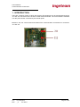
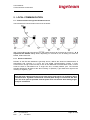
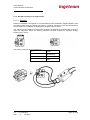
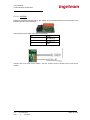
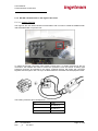
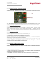
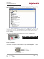
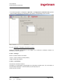
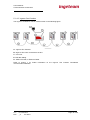
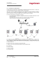
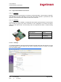
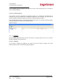
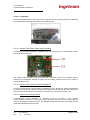
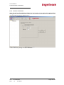
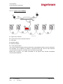
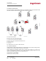
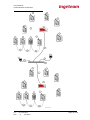
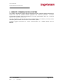
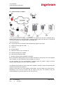
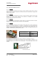
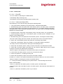
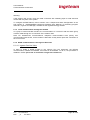
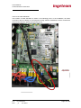
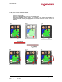
COMMUNICATION ACCESSORIES
Ref: AAX2002IKI01
Rev: _A
Accessories Installation Manual
Ingeteam Energy S.A.
06/2010
User's Manual
Communication Accessories
Note: In its commitment to ongoing product
improvement, Ingeteam Energy S.A. reserves the
right to amend this document with no prior notice.
Table of Contents
1.
INTRODUCTION ............................................................................................................................ 6
2.
LIST OF ACCESSORIES .................................................................................................................... 7
3.
INVERTER IDENTIFICATION ........................................................................................................... 8
4.
GENERAL SAFETY CONDITIONS ..................................................................................................... 9
5.
LOCAL COMMUNICATION ........................................................................................................... 10
5.1
Communication through the RS-485 serial line ................................................... 10
5.1.1
General comments ............................................................................................................. 10
5.1.1.1
Topology ................................................................................................................... 11
5.1.1.2
Speed ........................................................................................................................ 11
5.1.1.3
Half Duplex................................................................................................................ 11
5.1.1.4
Cabling ...................................................................................................................... 11
5.1.1.5
End of line ................................................................................................................. 11
5.1.1.6
Protective shield ....................................................................................................... 11
5.1.2
RS-485 accessories for Ingecon Sun ................................................................................... 12
5.1.2.1
AAP0034.................................................................................................................... 12
5.1.2.2
AAP0022.................................................................................................................... 13
5.1.3
RS-485 communication in the Ingecon Sun units ............................................................... 14
5.1.3.1
Ingecon Sun Lite ........................................................................................................ 14
5.1.3.2
Ingecon Sun Smart, Power and PowerMax............................................................... 15
5.1.3.3
Ingecon Sun String Control ....................................................................................... 15
5.1.3.4
Models prior to 2009 ................................................................................................ 15
5.1.4
Connection of the local PC and RS-485 PC accessories ...................................................... 15
5.1.4.1
AAP0057 USB to RS-485 converter .......................................................................... 15
5.1.4.1.1 Installation of the driver....................................................................................... 15
5.1.4.1.2 Settings................................................................................................................. 16
5.1.4.1.3 Connections ......................................................................................................... 16
5.1.4.2
AAP0058 - RS-485 to RS-232 Converter .................................................................... 17
5.1.4.2.1 Settings: ............................................................................................................... 17
5.1.4.2.2 Connections ......................................................................................................... 17
5.1.4.3
Ingecon Sun Combox ................................................................................................ 18
5.2
Local Ethernet communication ........................................................................... 19
5.2.1
Ingecon Sun Ethernet accessories ...................................................................................... 20
Ref.:
AAX2002IKI01
Rev.:
_A
Jun-2010
Page 2 of 56
User's Manual
Communication Accessories
5.2.1.1
AAX0023 ................................................................................................................... 20
5.2.1.2
AAX0004 ................................................................................................................... 20
5.2.1.2.1 Settings................................................................................................................. 20
5.2.1.2.2 Restoring the IP .................................................................................................... 21
5.2.1.3
AAP0067.................................................................................................................... 21
5.2.1.3.1 Settings................................................................................................................. 21
5.2.1.3.2 IP restoration ....................................................................................................... 23
5.2.1.4
AAS0173 .................................................................................................................... 24
5.2.1.5
AAS0174 .................................................................................................................... 24
5.2.2
Ethernet communication with the Ingecon Sun units ........................................................ 25
5.2.2.1
Ingecon Sun Lite ........................................................................................................ 25
5.2.2.1.1 How to disable the factory set RS-485 communication ....................................... 25
5.2.2.1.2 Installation ........................................................................................................... 26
5.2.2.2
Ingecon Sun Smart, Power and PowerMax ............................................................... 26
5.2.2.3
Ingecon Sun Power UL and PowerMax UL ................................................................ 26
5.2.2.4
Ingecon Sun String Control ....................................................................................... 26
5.2.2.5
Models prior to 2009 ................................................................................................ 27
5.2.3
Local PC connection ........................................................................................................... 28
5.2.3.1
Ingecon Sun COMBOX ............................................................................................... 29
5.3
Wireless communication .................................................................................... 30
5.3.1
General comments ............................................................................................................. 30
5.3.2
Wireless communication accessories for Ingecon Sun....................................................... 33
5.3.2.1
AAX0005 ................................................................................................................... 33
5.3.2.2
AAX0009 ................................................................................................................... 33
5.3.2.3
AAX0011 ................................................................................................................... 33
5.3.2.4
AAX0012 ................................................................................................................... 33
5.3.3
Wireless communication ISM868 in the Ingecon Sun units ............................................... 33
5.3.3.1
Ingecon Sun Lite ........................................................................................................ 33
5.3.3.2
Ingecon Sun Smart, Power and PowerMax, and Ingecon Sun String Control ........... 33
5.3.4
Local PC connection – Ingecon Sun Combox ...................................................................... 33
6.
REMOTE COMMUNICATION SYSTEM .......................................................................................... 34
6.1
Communication via GPRS ................................................................................... 35
6.1.1
General comments ............................................................................................................. 36
6.1.2
Ingecon Sun GPRS accessories ........................................................................................... 37
6.1.2.1
AAX0007 ................................................................................................................... 37
6.1.2.2
AAX0022 ................................................................................................................... 37
6.1.2.3
AAX0018 ................................................................................................................... 37
6.1.2.4
AAX0001 ................................................................................................................... 37
6.1.2.4.1 Status LEDs ........................................................................................................... 38
6.1.2.4.1.1 Red LED ......................................................................................................... 38
6.1.2.4.1.2 Yellow and Green LEDs ................................................................................. 38
6.1.3
Local communication through the modem ........................................................................ 39
6.1.4
GPRS communication in the Ingecon Sun units ................................................................. 39
6.1.4.1
Ingecon Sun Lite Units .............................................................................................. 39
6.1.4.2
Ingecon Sun Smart, Power and PowerMax units ...................................................... 42
6.1.4.3
Units prior to 2009 .................................................................................................... 42
6.1.5
Ingecon Sun Combox .......................................................................................................... 42
6.1.6 .................................................................................................................................................. 42
6.2
Remote communication via Ethernet ................................................................. 43
6.2.1
6.2.2
6.3
Remote communication via Ethernet to the Ingecon Sun units ........................................ 44
Connection of the remote PC ............................................................................................. 44
GSM Communication ......................................................................................... 45
Ref.:
AAX2002IKI01
Rev.:
_A
Jun-2010
Page 3 of 56
User's Manual
Communication Accessories
6.3.1
General comments ............................................................................................................. 45
6.3.2
Ingecon Sun GSM accessories ............................................................................................ 45
6.3.3
GSM communication with the Ingecon Sun units .............................................................. 45
6.3.4
Connection of the remote PC and GSM accessories for PC................................................ 45
6.3.4.1
Modem AAP0059 ...................................................................................................... 45
7.
Ingecon Sun Combox .................................................................................................................. 46
7.1
AAX0014 - GPRS Modem kit for AAX0006 ........................................................... 47
7.2
AAX0013 - Radio Kit for AAX0006 ....................................................................... 47
7.3
AAX0012 ........................................................................................................... 47
8.
FREQUENTLY ASKED QUESTIONS ................................................................................................ 48
9.
IMPORTANT SAFETY CONDITIONS .............................................................................................. 50
10. ....................................................................................................................................................... 54
Ref.:
AAX2002IKI01
Rev.:
_A
Jun-2010
Page 4 of 56
User's Manual
Communication Accessories
Related documentation
Ref.:
AAX2002IKI01
Rev.:
_A
Jun-2010
Page 5 of 56
User's Manual
Communication Accessories
1. INTRODUCTION
There are a number of ways in which the Ingecon Sun equipment can be monitored through the
J11 and J12 connectors on the inverter control electronics board. The control board is mounted
over the power board, connected by four divider posts.
Marked in red, the control board and locationof the communication accessories on connectors
J11 and J12:
Ref.:
AAX2002IKI01
Rev.:
_A
Jun-2010
Page 6 of 56
User's Manual
Communication Accessories
2. LIST OF ACCESSORIES
The following accessories and modification kits are available:
AAP0022
For RS-485 communication with Ingecon Sun Smart, Ingecon Sun Power,
Ingecon Sun PowerMax units and three phase inverter models prior to 2009.
AAP0034
For RS-485 communication with single phase models prior to 2009.
AAP0057
USB-RS-485 Converter.
AAP0058
RS232-RS-485 Converter.
AAP0059
GSM external modem
AAP0067
For Ethernet communication with Ingecon Sun Smart, Ingecon Sun Power,
Ingecon Sun PowerMax units and all equipment prior to 2009.
AAS0173
For Ethernet communication with Ingecon Sun Smart 15 UL and Ingecon Sun
Smart 25 UL units.
AAS0174
For Ethernet communication with Ingecon Sun Power 100 UL units.
AAX0001
For GPRS communication with Ingecon Sun Smart, Ingecon Sun Power,
Ingecon Sun PowerMax units and three phase inverter models prior to 2009.
AAX0004
For Ethernet communication with Ingecon Sun Smart, Ingecon Sun Power,
Ingecon Sun PowerMax units and three phase inverter models prior to 2009.
AAX0005
For wireless communication with the Ingecon Sun Smart, Ingecon Sun Power,
Ingecon Sun PowerMax units and three phase inverter models prior to 2009.
AAX0006
Ingecon Sun Combox centralised communication hardware.
AAX0007
For GSM communication with single phase inverter models prior to 2009.
AAX0009
For wireless and RS-485 communication with Ingecon Sun Smart, Ingecon
Sun Power, Ingecon Sun PowerMax units and three phase inverter models
prior to 2009.
AAX0011
Logical Zone Modification Kit in radio AAX0005.
AAX0012
Logical Zone Modification Kit in radio AAX0009 for AAX0006.
AAX0013
Radio Kit for AAX0006.
AAX0014
GPRS modem kit for AAX0006.
AAX0018
1900MHz band kit for GPRS modem.
AAX0022
For GPRS communication with Ingecon Sun Lite units.
AAX0023
For Ethernet communication with Ingecon Sun Lite units.
AAY0013
Harting type push-pull connector for Ingecon Sun Lite units.
Ref.:
AAX2002IKI01
Rev.:
_A
Jun-2010
Page 7 of 56
User's Manual
Communication Accessories
3. INVERTER IDENTIFICATION
It is absolutely essential to use a different identifier number for each and every inverter with
which communication is to be established. To change the inverter node number, please refer to
the appropriate installation manual.
Ingecon Sun Lite single phase models. Refer to document AAY2000IKH01.
Ingecon Sun Smart (10-30 kW) three phase models. Refer to document AAS2000IKH02.
Ingecon Sun Power (50-100 kW with transformer) three phase models. Refer to document
AAS2000IKH01.
Ingecon Sun PowerMax (Modular, 100TL and 125TL) three phase models. Refer to
document AAV2000IKH01.
Ingecon Sun String Control box. Refer to document AAS2002IKH01.
Single phase models prior to 2009. Refer to document AAP2000IKH01.
Three phase models of 100 kW or more, prior to 2009. Refer to document AAV2000IKH01
supplied with the equipment.
Other three phase models prior to 2009. Refer to document AAS2000IKH01 supplied with
the equipment.
Ref.:
AAX2002IKI01
Rev.:
_A
Jun-2010
Page 8 of 56
User's Manual
Communication Accessories
4. GENERAL SAFETY CONDITIONS
Please read section 9 and always refer to the installation manual corresponding to the Ingecon
Sun equipment in which the communication accessory is to be installed.
Ref.:
AAX2002IKI01
Rev.:
_A
Jun-2010
Page 9 of 56
User's Manual
Communication Accessories
5. LOCAL COMMUNICATION
5.1 Communication through the RS-485 serial line
The RS-485 local communication schema is as follows:
With inverters B and A connected by bus and media converter C connected to a local PC - D. E
represents the RS-485 cabling whilst, depending on converter C, the F cabling can either be
RS232, USB or Ethernet.
5.1.1 General comments
RS-485, as the EIA-485 standard is generally known, defines the electrical characteristics of
transmitters and receivers in a local, low cost digital communications system in noisy
environments. Its high noise immunity is due to the differential communication mode, in other
words the data is transmitted over a single two wire, normally twisted, pair. The EIA-485
standard defines the B signal as the "Non inverting" or positive (+) pin whilst the A signal is the
inverting or negative (-) pin.
Solar PV plant cabling generally carries high energy flows which can negatively affect
communication. Ingeteam recommends a careful plant design to ensure that the data
lines are as far apart as possible from the power lines and that the total cabling length
is kept to a minimum.
Ref.:
AAX2002IKI01
Rev.:
_A
Jun-2010
Page 10 of 56
User's Manual
Communication Accessories
5.1.1.1 Topology
The recommended cabling arrangement is a series of consecutive nodes, also called a bus or
line configuration. A star, ring or multiply connected network is not recommended. Ingeteam
Energy also advises you not to be conservative in the number of nodes in each bus, by not
connecting more than 30 items of equipment.
In a bus topology, it is best to have the master centrally located in the bus, in order to ensure
optimum signal strength to as many slaves as possible.
5.1.1.2 Speed
The communication speed in the Ingecon Sun units is 9600bps.
5.1.1.3 Half Duplex
In the Ingecon Sun units, communication via the RS-485 line is made with two wires in the Half
Duplex mode. In this configuration, the same pair of wires is used for the data sent and that
received, with the Ingecon Sun Manager software being responsible for ensuring that two
devices to not simultaneously access the bus.
5.1.1.4 Cabling
A "shielded twisted pair" type cable is recommended, with a characteristic impedance of 100 120 Ohm, for example the Unitronic Bus IBS 2x2x0.22, made by LappKabel. A twisted pair
should be used for the B (+) and A (-) signal pair, and another for the GND.
Although the data is transmitted over a two-wire pair, the cabling of a GND is also
necessary to provide a common voltage reference for all the devices connected to the
bus. Some manufacturers forget this fact and only supply two wires, which could
create problems.
The third twisted pair remains free, but a cable of this type is recommended due to the lower
cost and greater availability, compared to two pairs. If in doubt, consult your cable supplier.
5.1.1.5 End of line
The standard recommends that, at either end of the RS-485 cabling, in this case the inverters
marked as B, 120 ohm end of line resistors should be installed. The various Ingecon Sun range
models already incorporate the said resistors.
Ingecon Sun Lite – The installation is made at the Harting connector of Kit AAY0013.
Single phase units prior to 2009, refer to section 5.1.2.1
Other equipment, refer to section 5.1.2.2
5.1.1.6 Protective shield
The cable shield is intended to protect communications from electrical noise, however its use
and utility is controversial. Initially, and for each cable section installed, only take the mesh to
GND on one of the section ends.
Ref.:
AAX2002IKI01
Rev.:
_A
Jun-2010
Page 11 of 56
User's Manual
Communication Accessories
5.1.2 RS-485 accessories for Ingecon Sun
5.1.2.1 AAP0034
Reference AAP0034 corresponds to communications board AAP0022, supplied together with
the internal cable and the Harting type fast-on connector required for the RS-485 serial line
communication for installation in single phase equipment prior to 2009.
The 120 Ohm end resistance for end of line equipment is supplied for mounting with no need to
open the equipment. Mount the Harting push-pull connector supplied by Ingeteam Energy
between pins 1 and 2.
The Harting connector pins correspond to:
Ref.:
AAX2002IKI01
Rev.:
_A
Jun-2010
Pin
Signal
1
RS-485 B (+)
2
RS-485 A (-)
5
GND
Page 12 of 56
User's Manual
Communication Accessories
5.1.2.2 AAP0022
Reference AAP0022 corresponds to the supply of the communications board required for the
RS-485 serial line communication.
The terminals of the cable connector correspond to:
Pin
Signal
1
RS-485 B (+)
2
RS-485 A (-)
6
GND
Jumper JP3 is the end of line resistor. This P3 Jumper must be closed on the end of line
inverter.
Ref.:
AAX2002IKI01
Rev.:
_A
Jun-2010
Page 13 of 56
User's Manual
Communication Accessories
5.1.3 RS-485 communication in the Ingecon Sun units
5.1.3.1 Ingecon Sun Lite
The Ingecon Sun Lite offers RS-485 communication with no need to install the additional RS485 AAX0022 board or open the unit.
To make the RS-485 connection with another inverter and / or media converter for the PC
connection, the installer will need to remove the protective cover and mount a Harting type
push-pull connector as indicated in the figure. Ingeteam Energy will supply this connector
together with the Ingecon Sun Lite if you included reference AAY0013 with the equipment order.
The Harting connector pins correspond to:
Ref.:
AAX2002IKI01
Rev.:
_A
Jun-2010
Pin
Signal
1
RS-485 B (+)
2
RS-485 A (-)
5
GND
Page 14 of 56
User's Manual
Communication Accessories
5.1.3.2 Ingecon Sun Smart, Power and PowerMax
Communications card AAP0022 must be mounted on the control board specific communications
connector.
The cabling shall be made to the board push-pull connector. There is no defined position on the
equipment housing for bringing out the cabling, however there are a number of ports available.
5.1.3.3 Ingecon Sun String Control
Communications card AAP0022 must be mounted on the String Control electronics board
specific communications connector and the cabling shall be made to the board push-pull
connector. The RS-485 cabling shall be passed through the PG cable gland available for this
purpose.
5.1.3.4 Models prior to 2009
Refer to the previous version of this document: AAX2002IKH01_B.
5.1.4 Connection of the local PC and RS-485 PC accessories
Given the fact that the PC does not incorporate an RS-485 port, a converter is required to
connect the bus formed by the Ingecon Sun equipment.
To connect the group of inverters to the PC, use an off-the-shelf RS-485 to RS-232 or USB
converter, configured in the «Multipoint» mode and «Two wire, Half Duplex» or else the
«AAP0057» and «AAP0058» supplied by Ingeteam Energy.
5.1.4.1 AAP0057 USB to RS-485 converter
Reference AAX0057 corresponds to the supply of a USB to RS-485 converter for connection to
a PC with Windows XP or later.
5.1.4.1.1 Installation of the driver
• Connect the converter to the computer USB port. The installation will start automatically and
CD-ROM should be selected as the driver source.
• The installation will prompt for the drivers again, and the same source should be indicated.
Ref.:
AAX2002IKI01
Rev.:
_A
Jun-2010
Page 15 of 56
User's Manual
Communication Accessories
• Once completed, open the device manager (Administrador de dispositivos) from the control
panel or else from the execute option in the start menu: Menú de Inicio -> Ejecutar ... and
enter devmgmt.msc.
• In ports Puertos (COM & LPT) you will see the new COMx port that the system has
associated with the converter, named USB Serial Port or FTDI USB Serial Port (depending on
the driver version). This port number will be used in the Ingecon Sun Manager configuration.
5.1.4.1.2 Settings
• The settings of the side switches must always remain as shown in the following figure:
PIN 1
PIN 2
PIN 3
PIN 4
ON
OFF
OFF
OFF
5.1.4.1.3 Connections
• Connect the two terminals on the terminal strip to the communications board, by pairing
converter terminal 2 to pin 1 of the communications board, and terminal 1 to pin 2.
Ref.:
AAX2002IKI01
Rev.:
_A
Jun-2010
Page 16 of 56
User's Manual
Communication Accessories
• The monitor program is configured in Opciones -> Configuración comunicaciones (options
- communications settings) by selecting the port number corresponding to the converter.
5.1.4.2 AAP0058 - RS-485 to RS-232 Converter
Reference AAP0058 corresponds to the supply of an RS-232 to RS-485 converter for
connection to a PC serial port.
5.1.4.2.1 Settings:
Set the converter switches as follows:
• Left to “T-RTS, R-/RTS” (central position)
• Right to DCE (top position)
5.1.4.2.2 Connections
•Connect the converter to the PC.
•Configure it for half duplex communication by connecting converter pins 1(T+) and 4(R+) to
communications board pin 1 and terminals 2(T-) and 3(R-) to pin 2.
•Power-up the converter.
Ref.:
AAX2002IKI01
Rev.:
_A
Jun-2010
Page 17 of 56
User's Manual
Communication Accessories
5.1.4.3 Ingecon Sun Combox
The Ingecon Su Bombox can be used as shown in the following figure:
A - Ingecon Sun Combox.
B –Ingecon Sun units connected to the bus
C – PC local.
E –RS-485 cabling.
D - USB or RS-485, or Ethernet Cable.
Refer to section 7 for further information on the Ingecon Sun Combox Centralised
communication hardware.
Ref.:
AAX2002IKI01
Rev.:
_A
Jun-2010
Page 18 of 56
User's Manual
Communication Accessories
5.2 Local Ethernet communication
All the Ingecon Sun Ethernet communication accessories incorporate Ethernet to serial port
conversion hardware and have a similar operation, set by default.
They have a fixed IP address assigned and are programmed as TCP servers to accept a
connection from the Ingecon Sun Manager client software. The default port number through
which connections are received is 7218. Only one client at a time is accepted.
For local communication, the following is required:
The serial Ethernet converter in equipment A and local computers D must be in the
same sub-network.
The number of the TCP port in which the converter accepts connections.
There are not two or more devices with the same IP address.
A – Ingecon Sun with AAX0004 (Ethernet and RS-485 communications card), or Ingecon Sun
Lite with AAX0023 (Ethernet and RS-485 communications card), or Ingecon Sun Smart 15 UL
with kit AAS0173, or Ingecon Sun Smart 25 UL with kit AAS0173, or Ingecon Sun Power 100
UL with kit AAS0174.
B –Ingecon Sun units connected to the same bus as A.
C –Ingecon Sun units with AAP0067 (Ethernet communications card).
D – Local PCs.
E –RS-485 cabling.
F –Ethernet cabling.
G – Network switch.
Ref.:
AAX2002IKI01
Rev.:
_A
Jun-2010
Page 19 of 56
User's Manual
Communication Accessories
5.2.1 Ingecon Sun Ethernet accessories
5.2.1.1 AAX0023
Reference AAX0023 corresponds to the supply of board AAX0004, communications cable RS485 AQL0089, flat cable AQL0090, and the PG cable gland required to guarantee the leak
tightness of the equipment at the Ethernet cable inlet connection.
5.2.1.2 AAX0004
Communications board AAX0004 / AAX0023 RS-485 interface permits Ethernet communication
with a number of Ingecon Sun units connected in a bus configuration. It is factory set with IP
address IP 192.168.127.253. This accessory does not incorporate the alarm or report sending
functions.
Push-pull pin
Signal
1
RS-485 B (+)
2
RS-485 A (-)
6
GND
5.2.1.2.1 Settings
To change this address, open the Internet navigator and enter http://192.168.127.253. A Log-in
prompt will appear in which neither the user name or password need to be entered. This takes
you to the following page:
Ref.:
AAX2002IKI01
Rev.:
_A
Jun-2010
Page 20 of 56
User's Manual
Communication Accessories
The IP address can be changed in the "Network" section. After changing this, do not forget to
click on "Apply Settings".
5.2.1.2.2 Restoring the IP
The AAX004 board incorporates the Ethernet series TTL XPORT-03 manufactured by
Lantronix. If you do not know the IP address configured in the converter, you can use the
“Device Installer” software provided by Lantronix to make a MAC level search.
The „deviceinstaller‟ search on the Lantronix web returns links to the software download page.
Install and proceed as shown in the following image.
Click on „Search‟.
5.2.1.3 AAP0067
Board AAP0067 offers Ethernet to serial conversion for a single Ingecon Sun unit. It is factory
set with IP address 192.168.127.254.
5.2.1.3.1 Settings
If you want to change this address, you need to open the Internet navigator and enter
http://192.168.127.254. The following page will appear:
Ref.:
AAX2002IKI01
Rev.:
_A
Jun-2010
Page 21 of 56
User's Manual
Communication Accessories
To change the IP address, access the Network Settings folder and click on the "Submit" button
to apply the changes.
Ref.:
AAX2002IKI01
Rev.:
_A
Jun-2010
Page 22 of 56
User's Manual
Communication Accessories
5.2.1.3.2 IP restoration
Board AAP0067 incorporates the Ethernet - serial converterTTL NE-4100T manufactured by
MOXA. If you do not know the IP address configured for the converter, you can use the “NPort
Search Utility” software supplied by Moxa to make a MAC level search.
The „NPort Search Utility 4100‟ on the Moxa website returns the link to the installation file. Install
and proceed as shown in the following images:
Click on „Search‟:
A dialogue is shown and which will look for devices during 10 seconds:
And will finally present the results.
Ref.:
AAX2002IKI01
Rev.:
_A
Jun-2010
Page 23 of 56
User's Manual
Communication Accessories
5.2.1.4 AAS0173
The 25-15kW UL units can optionally be supplied with kit AAS0173 for Ethernet communication.
It incorporates an Ethernet - RS-485 converter to be used like the AAX0004, providing Ethernet
connectivity to all the units connected in a bus configuration.
5.2.1.5 AAS0174
The 100kW UL can optionally be supplied with kit AAS0174 for Ethernet communication. It
incorporates an Ethernet - RS-485 converter to be used like the AAX0004, providing Ethernet
connectivity to all the units connected in a bus configuration.
Ref.:
AAX2002IKI01
Rev.:
_A
Jun-2010
Page 24 of 56
User's Manual
Communication Accessories
5.2.2 Ethernet communication with the Ingecon Sun units
5.2.2.1 Ingecon Sun Lite
In order to install an Ethernet communication card in the Ingecon Sun Lite units, you first need
to disable the RS-485 communication, installed as standard. To do so, proceed as described in
5.2.2.1.1. You can then install the accessory.
5.2.2.1.1 How to disable the factory set RS-485 communication
The following photo (with the inverter control card removed) shows the location of lead
AQL0053 which must be removed in order to disable the RS485 communication through
connector J19 on the power board.
This must be replaced by cable AQL0090 supplied with the Ingecon Sun Lite communication
accessories.
Ref.:
AAX2002IKI01
Rev.:
_A
Jun-2010
Page 25 of 56
User's Manual
Communication Accessories
5.2.2.1.2 Installation
Remove the blank shown in the photo from the Ingecon Sun Lite housing and fit a 20 diameter
PG cable gland through which the Ethernet Cabling will pass.
5.2.2.2 Ingecon Sun Smart, Power and PowerMax
Communications board AAP0067 / AAX0004 must be mounted on the control board specific
communications connector.
The cabling shall be made to the board push-pull connector. There is no particular position
defined on the equipment housing for taking out the cabling, however there are a number of
ports available to do so.
5.2.2.3 Ingecon Sun Power UL and PowerMax UL
For these units, Ethernet communication is available, to order, through an off-the-shelf Ethernet
to serial converter which is factory set with the IP address IP 192.168.127.254 and, like the rest
of the Ethernet communication accessories, it receives TCP connections at port 7128.
5.2.2.4 Ingecon Sun String Control
Communications board AAP0067 or AAX0004 must be mounted on the specific
communications connector on the String Control electronics board, and the cabling shall be
made to the board push-pull connector. The RS-485 cabling shall be taken out through the PG
cable gland designed for this purpose.
Ref.:
AAX2002IKI01
Rev.:
_A
Jun-2010
Page 26 of 56
User's Manual
Communication Accessories
5.2.2.5 Models prior to 2009
Use the earlier version of this document, AAX2002IKH01_.
Ref.:
AAX2002IKI01
Rev.:
_A
Jun-2010
Page 27 of 56
User's Manual
Communication Accessories
5.2.3 Local PC connection
Open the Ingecon Sun Manager software on the PC and, on the right hand communication
settings panel, select Ethernet as the means of communication and enter the IP address for the
communication accessory and the port nº.
• Then connect by clicking on button “Conectar”.
Ref.:
AAX2002IKI01
Rev.:
_A
Jun-2010
Page 28 of 56
User's Manual
Communication Accessories
5.2.3.1 Ingecon Sun COMBOX
A - Ingecon Sun Combox.
B – Ingecon Sun units connected to the bus.
C –Local PCs
E –RS-485 Cabling.
D - Ethernet Cabling.
G – Local network switch.
The Combox Ethernet interface offers an Ethernet to serial gateway similar to the one offered by
the AAX0004. Its IP address by default is 192.168.127.253 and, like the other Ethernet
communication accessories, it accepts TCP connections at port 7128.
Please refer to section 7 for further information on the Ingecon Sun Combox Centralised
communication hardware.
Ref.:
AAX2002IKI01
Rev.:
_A
Jun-2010
Page 29 of 56
User's Manual
Communication Accessories
5.3 Wireless communication
For a typical wireless communication schema, a pc F monitors a group of inverters B, C and D
that share a wireless network with the Ingecon Sun Combox accessory A.
A – Ingecon Sun Combox.
B –Ingecon Sun units with radio AAX0005.
C – Ingecon Sun units with radio AAX0009.
D –Ingecon Sun units connected to RS-485 bus of C.
E –RS-485 cabling.
F – PC local.
G – Cabling from PC to Combox: USB or Ethernet.
5.3.1 General comments
Communication by radio means that there is no need to install communications cabling, thereby
avoiding the risk of voltage surges caused by the said cabling.
Radios AAX0005 and AAX0009, together with the master radio installed in the Ingecon Sun
Combox communications equipment, form a totally transparent wireless serial bus for the
Ingecon Sun Manager software. The bus characteristics are:
Communication on band ISM868.
Radiated power 500mW (27dBm).
Ref.:
AAX2002IKI01
Rev.:
_A
Jun-2010
Page 30 of 56
User's Manual
Communication Accessories
Radio interface at 19200bps.
Serial interface at 9600bps.
Communication between the Combox and the inverter radios is established in point - multipoint
mode. The Combox transmits by broadcast the requests received from a PC and, in the same
way as for a cabled system, only the inverter whose node nº coincides with the request contents
will respond to the request.
Radio communication between the Combox and the various Ingecon Sun accessories is
organised into what have been termed "Logical Zones", such that if the radio in a Combox
cannot cover the entire plant area, then a second Logical Zone is configured.
In ideal conditions of direct visibility and high antenas, the radiated power of 500 mW permits a
range of various kilometres. However in practice this distance is drastically reduced by the
environmental conditions.
By default, all accessories operate in Logical Zone nº 1 and ignore any communication outside
their Logical Zone.
All logical zones share the same radio-electric channel and therefore, simultaneous
communication in various zones is not possible.
For example:
In the following communications schema, two Combox A and B, connected to the same local
network, each control a Logical Zone.
As the radios ignore any communications outside their Zone, it is possible to repeat a node nº
which is already being used in another zone.
Monitoring is through Ethernet from a local PC and the Combox network address cannot be the
same.
Ref.:
AAX2002IKI01
Rev.:
_A
Jun-2010
Page 31 of 56
User's Manual
Communication Accessories
Ref.:
AAX2002IKI01
Rev.:
_A
Jun-2010
Page 32 of 56
User's Manual
Communication Accessories
5.3.2 Wireless communication accessories for Ingecon Sun
5.3.2.1 AAX0005
Board AAX0005 enables wireless communication to an Ingecon Sun unit.
5.3.2.2 AAX0009
Board AAX0009 enables wireless communication to an Ingecon Sun unit and any units
connected by RS-485 to the Ingecon Sun.
5.3.2.3 AAX0011
Indicate this kit in your order in order to configure a radio AAX0005 or AAX0009 in a Logical
Zone other than 1.
5.3.2.4 AAX0012
Indicate this kit in your order in order to configure a Combox in a Logical Zone other than 1.
5.3.3 Wireless communication ISM868 in the Ingecon Sun units
5.3.3.1 Ingecon Sun Lite
In order to install a wireless communication card in the Ingecon Sun Lite unit, it is first necessary
to disable the Rs-485 communication installed as standard. The procedure to do so is described
in 5.2.2.1.1. Once this has been disabled, the accessory can be installed.
5.3.3.2 Ingecon Sun Smart, Power and PowerMax, and Ingecon Sun String Control
The wireless communication board, either the AAX0005 or the AAX0009, must be mounted on
the control board specific communications connector. For the AAX0009, the RS-485 is made to
the board push-pull connector. There is no defined position on the equipment casing to serve as
an inlet port for the antenna and RS-485 cabling, if present, but there are a number of auxiliary
ports available.
5.3.4 Local PC connection – Ingecon Sun Combox
As shown in the figure above, the local PC can be connected by USB or by Ethernet.
Please refer to section7 for further information on the Ingecon Sun Combox Centralised
communication hardware.
Ref.:
AAX2002IKI01
Rev.:
_A
Jun-2010
Page 33 of 56
User's Manual
Communication Accessories
6. REMOTE COMMUNICATION SYSTEM
This section describes the Ingecon Sun accessories and the equipment settings required, the
remote PCs and the possible network equipment that could be present in a remote
communication system, which is understood to be the communication with one or several
Ingecon Sun units from a remote PC.
You are advised to ensure that the local communication is functioning correctly before
undertaking the installation of the remote communication system.
Ingeteam supplies accessories for remote communication via a GPRS network and via
Ethernet.
Ref.:
AAX2002IKI01
Rev.:
_A
Jun-2010
Page 34 of 56
User's Manual
Communication Accessories
6.1 Communication via GPRS
In the typical schema for GPRS communication, an Ingecon Sun unit A is equipped with a
GPRS modem and this is accessed from a remote computer which can either be a computer G
in an ADSL network or a computer I with a 3G/GPRS card.
The other items are:
B - Ingecon Sun units connected to the RS-485 bus of Ingecon Sun unit A.
C - Media converter (RS-232, USB, … ).
D - Local PC
E - RS-485 cabling.
F - Cable from the PC up to converter C.
G - Remote computer in a network.
H - Remote local network firewall.
I - Remote computer with a GPRS/3G connection.
E1 is the RS-485 cabling section from the media converter to the Ingecon Sun unit equipped
with a modem. You are advised to keep the length to a minimum.
In a bus topology, you are recommended to centrally locate the master in order to ensure
optimum signal strength to as many slaves as possible.
In a GPRS communication, the bus master is the modem in unit A, in charge of transmitting the
requests from and to the remote PC.
However, when there is no active CPRS communication, the bus master can be the local PC.
Depending on the local PC location and the length of the bus, on occasion it may be
recommendable to locate the modem at one end of the bus.
Ref.:
AAX2002IKI01
Rev.:
_A
Jun-2010
Page 35 of 56
User's Manual
Communication Accessories
6.1.1 General comments
The GPRS communication is made through the mobile phone operator communication
networks. Access to these networks is a service which must be subscribed to by the customer.
Likewise, the customer should ensure that the installation has network coverage.
The M2M (Machine 2 Machine) rates are adequate for devices such as the modems in the
Ingecon Sun units, which are permanently connected to the network but which have a very low
data traffic.
Apart from these rates, each operator uses its own criteria to bill the GPRS communication,
which can be based on data volume, connection time or even both.
For this reason, and to avoid unpleasant surprises, it is advisable to monitor consumption during
the first few days after installing a communication system of this type.
Alternatively, it is possible to disable the GPRS communication in a modem and it will then
perform like a GSM modem. However, a missed phone call is sufficient for the modem to
connect to GPRS and wait for a connection during the following hour. Once this hour has
passed, it will return to the GSM mode.
The Ingecon Sun modems are supplied as standard with parameters APN (APNSERV, APNUN
y APNPW) and which are necessary for M2M communications with the leading cell phone
operators in Spain, France and Italy.
It is also possible to establish customised APN parameter, which makes it possible to work with
new operators or VPN network services.
Ref.:
AAX2002IKI01
Rev.:
_A
Jun-2010
Page 36 of 56
User's Manual
Communication Accessories
6.1.2 Ingecon Sun GPRS accessories
6.1.2.1 AAX0007
Reference AAX0007 corresponds to the supply of modem AAX0001 together with the internal
cable and fast-on connector required for the RS-485 serial line communication in single phase
equipment prior to 2009.
6.1.2.2 AAX0022
Reference AAX0022 corresponds to the supply of modem AAX0001 together with flat cable
AQL0089 and RS-485 cable AQL0089. This reference is adequate for the GPRS
communication in the Ingecon Sun Lite units.
6.1.2.3 AAX0018
The various references incorporating the GPRS modem are configured to function in Europe.
Request this kit to enable the modem to function in the United States.
6.1.2.4 AAX0001
Reference AAX0001 corresponds to the modem for three phase units, a basic component for
the rest of the GPRS accessories. It comprises a motherboard and superimposed GPRS
modem card, the corresponding antenna with its cable and three status indicator LEDs. The
antenna is equipped with a magnetic base to secure it in place. The SIM card, which is not
included, must be released from its PIN access code.
Push-pull connector Pins
Signal
1
RS-485 B (+)
2
RS-485 A (-)
4
GND
It is mandatory for the inverter fitted with modem AAX0001 to be identified as number 1.
The arrangement of the jumpers on the boards in the other inverters is identical to the
arrangement given for the RS-485 line communication, for the intermediate and the end
inverters.
Ref.:
AAX2002IKI01
Rev.:
_A
Jun-2010
Page 37 of 56
User's Manual
Communication Accessories
6.1.2.4.1 Status LEDs
6.1.2.4.1.1 Red LED
- On: The modem is searching for a GSM network.
- Fast flashing: Busy receiving a call.
- Slow flashing: Connected to the GSM network awaiting calls.
6.1.2.4.1.2 Yellow and Green LEDs
After switching on, the LEDs should go through the following states.
1 - “Two green flashes, followed by two yellow flashes”: AWAITING SIM CARD
2 - Simultaneously green and yellow with "three flashes, pause, one flash, pause". AWAITING
LOG ONTO NETWORK (in this status the red light will be on). THE MOST RECENT AAX1000_i
VERSIONS WILL WAIT SEVERAL MINUTES WITH THE RED LIGHT FLASHING BEFORE
MAKING A LOG-ON CHECK
3 - Continuous green, yellow with " three flashes, pause, one flash, pause": not yet initialised.
4 - Continuous green, yellow with " three flashes, pause, one flash, pause": initialised, not yet
logged on to the GSM network
5 - Simultaneously green and yellow with "three flashes, pause", checking the modem setting.
Once the modem setting has been checked, the modem will connect to the GPRS network:
6 - Green, with " three flashes, pause" and yellow off: connecting to the GPRS.
7 - Green with " three flashes, pause" and yellow on: connected to GPRS, notifying IP.
It is ready to receive connections from the Ingecon Sun Manager when:
8 - Green with "four flashes, pause": ready to receive connections, for GPRS and for GSM.
9 - Green with "one flash, pause" and yellow off: only ready for GSM calls (for lack of GPRS
coverage or because the GPRS option is disabled).
When the Ingecon Sun Manager is connected to the modem, the states are:
10 - Green with "five flashes, pause": the PC has connected via GPRS.
11 -Green and yellow on: accepting incoming call.
12 -Green with "two flashes, pause": the PC has connected via GSM.
In states 8, 9, 10 and 11 the yellow led indicates the presence of alarms in one of the inverters.
When the modem is checking the inverters for possible alarms:
13 - “Three green flashes, followed by three yellow flashes": communicating with inverters.
Other undesired states:
- Green on, yellow with "two flashes, pause, one flash, pause". NO SIM CARD.
- Green and yellow with "two flashes, pause, one flash, pause": SIM card PIN code request not
disabled.
- Green on, yellow with "six flashes, pause": log-on denied.
Ref.:
AAX2002IKI01
Rev.:
_A
Jun-2010
Page 38 of 56
User's Manual
Communication Accessories
Warning:
If the antenna has a lead, cover the metal connection with insulating tape to avoid electrical
contact with live parts of the system.
To configure the SMS alarms, refer to section "4.2.5.1 Report and Alarm Configuration" in the
help section of «AAX2005IKE01 Monitoring Software User Manual» of monitoring program
AAX1001, Ingecon Sun Manager, available on the Ingeteam Energy website.
6.1.3 Local communication through the modem
In a group of interconnected inverters, the communication of a local PC with the whole group
must be made through the J3 connector of the modem used.
Note: For simultaneous communications, telephone communications have priority over
communication with the PC, as the modem is fitted with a relay which opens the connection at
the J3 connector.
6.1.4 GPRS communication in the Ingecon Sun units
6.1.4.1 Ingecon Sun Lite Units
In order to install a GPRS modem in the Ingecon Sun Lite equipment, the RS-485
communication, installed as standard, first needs to be disabled. To do so, the procedure is
detailed in section ¡Error! No se encuentra el origen de la referencia..
Ref.:
AAX2002IKI01
Rev.:
_A
Jun-2010
Page 39 of 56
User's Manual
Communication Accessories
Then locate cable AQL0055.
The location of cable AQL0055 is shown in the following photo. In the installation, the cable
connection with the Harting on the equipment casing shall be maintained, however it should be
disconnected from the power board printed circuit.
Ref.:
AAX2002IKI01
Rev.:
_A
Jun-2010
Page 40 of 56
User's Manual
Communication Accessories
Finally, the accessory should be installed.
1, 2 and 3: Disconnect the AQL0055 cable RS-485 connector from the power board.
4: Connect the modem.
5: Connect cable AQL0089 to the free end of AQL0055.
6: Connect AQL0089 to the modem. As described in the section corresponding to
modem AAX0001, selecting the appropriate one to either connect a local PC or a bus of
inverters.
Ref.:
AAX2002IKI01
Rev.:
_A
Jun-2010
Page 41 of 56
User's Manual
Communication Accessories
6.1.4.2 Ingecon Sun Smart, Power and PowerMax units
Modem AAX0001 must be mounted on the control board specific communications connector,
and the cabling shall be made to the board push-pull connector. There is no defined position on
the equipment casing for bringing in the antenna and RS-485 cabling, if present, however there
are a number of auxiliary ports available.
6.1.4.3 Units prior to 2009
The AAX0007 should be mounted. Communications modem AAX0001 must be mounted on the
control board specific communications connector, and the cabling shall be made to the board
push-pull connector. There is no defined position on the equipment casing for passing through
the antenna and RS-485 cabling, if present, however there are a number of auxiliary ports
available. The appropriate PG diameter should be used for the cabling port in order to maintain
the equipment leak tightness.
6.1.5 Ingecon Sun Combox
Optionally, the Combox can include a GPRS modem.
A – Ingecon Sun Combox with GPRS modem
B - Ingecon Sun units connected to the RS-485 bus of Combox A.
C - Remote computer in the network
D - Remote computer with a GPRS/3G connection.
Please refer to section ¡Error! No se encuentra el origen de la referencia. For further
information on the Ingecon Sun Combox Centralised communication hardware.
Ref.:
AAX2002IKI01
Rev.:
_A
Jun-2010
Page 42 of 56
User's Manual
Communication Accessories
6.2 Remote communication via Ethernet
The following figure shows a typical remote communication schema in which the aim is to
communicate with equipment items A and B through computer G.
Key:
A - Inverter with card AAX0004 or AAX0023 or Ingecon Sun Power UL unit
B - Ingecon Sun units on the same RS-485 bus as unit A.
C – Ingecon Sun units with board AAP0067.
D – Local PCs
E –RS-485 cabling.
F- Ethernet cabling.
G - Local switch.
H - Local firewall.
I - Remote firewall.
J - Remote computer.
H - Ethernet UTP cabling.
I - RS-485 cabling
Ref.:
AAX2002IKI01
Rev.:
_A
Jun-2010
Page 43 of 56
User's Manual
Communication Accessories
6.2.1 Remote communication via Ethernet to the Ingecon Sun units
Taking for granted that the local communication via Ethernet from computer D is correct, as far
as the Ingecon Sun equipment is concerned, the only thing to be configured is the Default
Gateway of the converter installed in unit A.
If there are several devices, it will be necessary to change the TCP port number in which the
connections are received, so that the same number is not repeated. For example, for three
devices, the first would be configured on port 7128, the second on 7129 and the third on 7130.
6.2.2 Connection of the remote PC
For the remote PC, you need to know the public address of router H in order to enter it in the
plant communications configuration in the Ingecon Sun Manager software.
Router H must also be correctly configured:
Configure the NAT or port redirecting of router E to accept incoming connection at the
TCP port specified on the converter.
Redirect the incoming connections through the said port to the private IP of the
converter at A.
If there are several converters, repeate the NAT configuration process with its TCP port
and corresponding address.
And at router I, you need to permit outgoing connections at the corresponding port.
Ref.:
AAX2002IKI01
Rev.:
_A
Jun-2010
Page 44 of 56
User's Manual
Communication Accessories
6.3 GSM Communication
6.3.1 General comments
6.3.2 Ingecon Sun GSM accessories
The hardware to be used is as described in section Modem AAX0001 with the GPRS option
disabled.
6.3.3 GSM communication with the Ingecon Sun units
As this is the same hardware, section 6.1.4 is applicable
6.3.4 Connection of the remote PC and GSM accessories for PC
6.3.4.1 Modem AAP0059
• The modems are pre-set and, to operate them, they simply need to be connected to the
computer serial port.
• In Opciones -> Configuración comunicaciones (options - communication setting) select the
port number to which the modem is connected.
Enter the phone number and click on connect „Conectar’.
Wait until status "Estado" shows connected „Conectado’.
Ref.:
AAX2002IKI01
Rev.:
_A
Jun-2010
Page 45 of 56
User's Manual
Communication Accessories
7. INGECON SUN COMBOX
The Ingecon Sun Combox Centralised communication hardware, with reference AAX0006, is a
multi-purpose accessory offering the following possibilities:
Local connection of a PC to one or several inverters.
Centralised local wireless communication in one installation.
Centralised GPRS communication in one installation.
Historical data capture and recording of meteorological variables.
Historical data capture and recording of the power threshold imposed by the electricity
company and send it to the inverters.
The following figure shows where the connections should be made and the PG through
which the different cables should be passed.
A - 220V AC Power.
B - Power threshold cables.
C - Sensor cables for the analog inputs.
D - Cables for the modem and radio antennas.
E - Connector for 5V DC power source
F - Connector for Ethernet cable
G - Connector for USB type B cable
H - RS-485 input connector
I - RS-485 output connector.
The Ingecon Sun Combox is equipped with several analog inputs to connect sensors for
meteorological variables.
The inputs are:
2 inputs 0..10V or 0..20mA
1 input 0..2V or 0..20mA
1 input 0..400mV or 0..20mA
Ref.:
AAX2002IKI01
Rev.:
_A
Jun-2010
Page 46 of 56
User's Manual
Communication Accessories
2 inputs for PT100 wire probe
Finally, the board has 4 digital inputs to control the power that the inverters supply to the grid.
The configuration of these inputs is monitored every 30 seconds and if there are any changes, a
power change section is broadcast to the inverters.
7.1 AAX0014 - GPRS Modem kit for AAX0006
Optionally, the Combox incorporates a GPRS modem to install in the Combox. This modem is
configurable to send SMS alarms and reports in the same way as the GPRS AAX0001 modem.
7.2 AAX0013 - Radio Kit for AAX0006
Optionally the Combox incorporates a radio on band ISM868 for local communication with the
Ingecon Sun units.
7.3 AAX0012
Kit AAX0012 (kit to change the Logical Zone in radio AAX0009 for AAX0006) makes it possible
to change the Logical Zone of the radio installed in the Combox.
Ref.:
AAX2002IKI01
Rev.:
_A
Jun-2010
Page 47 of 56
User's Manual
Communication Accessories
8. FREQUENTLY ASKED QUESTIONS
Is it possible to remotely reconfigure the firmware of a more advanced version in order to
optimise the inverter operation?
Firmware reconfiguration must be performed by Ingeteam Energy personnel. In any case, a
more advanced version of the firmware installed in an item of equipment does not necessarily
mean an improvement in operation. Each firmware version is optimised for a specific topology.
Does the string box communication require a special configuration? Must the inverter function
as a gateway when string boxes are connected to the RS-485 network?
No. The string boxes are connected to the RS-485 grid in the same way as the inverters. They
function as yet another node. The inverter, therefore, does not function as a gateway to
communicate with the string boxes.
Is there a restriction on the number of nodes to be included in a RS-485 network?
Yes. Due to the Modbus protocol design, the greatest number of nodes is 247, although in
practice the environment conditions will make it difficult to establish correct communications with
this number of machines and installations are frequently planned with various independent
buses.
Is it possible to view the inverter data via the remote connection when the inverter is switched
off?
Yes, provided that the inverter is powered through an uninterrupted power system (UPS).
Obviously in these circumstances any instantaneous variables such as production, power or
output current will be shown with value of zero.
Can a GSM modem be configures as a GPRS modem?
Modems manufactured later than January 2007 have this GSM or GPRS configuration option.
This configuration is made through the INGECON SUN MANAGER application. The units
manufactured prior to this date are only for GSM communication and cannot be configured for
GPRS.
What should be done if there is no connection with the equipment via GSM/GPRS?
You first need to check whether the installation has coverage. The coverage status can be
determined through the status of the corresponding LED (see page 22 of the manual).
With the red LED continually on, the modem has no coverage (it is looking for a network).
In order to view the LEDs, the equipment needs to be opened. This should be done following
the general safety conditions included in this manual.
Should you have any doubts with regard to whether the SIM card is operating correctly,
disconnect the equipment, wait 10 minutes and then remove the SIM card and test it in another
unit in which you are sure that communications are correct.
Should you detect a SIM card malfunction, contact the Phone Company supplying the card,
which should confirm whether the card needs reconfiguring or is damaged.
Never remove the SIM card with the equipment connected to the power supply. In addition to
the obvious risk to persons, you are very likely to damage the SIM card.
Ref.:
AAX2002IKI01
Rev.:
_A
Jun-2010
Page 48 of 56
User's Manual
Communication Accessories
If the SIM card is shown to function OK, then repeat the operation with the modem to check that
this is not damaged.
Ref.:
AAX2002IKI01
Rev.:
_A
Jun-2010
Page 49 of 56
User's Manual
Communication Accessories
9. IMPORTANT SAFETY CONDITIONS
CAUTION
The operations detailed in this manual can only be performed by
suitably qualified personnel.
You are reminded that it is mandatory to comply with all applicable
safety legislation for electrical work. There is an electrical discharge
hazard.
It is mandatory to read and understand this entire manual before
manipulating, installing or operating this equipment.
CAUTION
Qualified personnel as referred to in this manual means personnel who
at least meet the requirements of all safety standards, rules,
regulations and legislation applicable to the equipment installation and
operating tasks.
The responsibility of appointing qualified personnel shall always fall to
the company at which the said personnel is employed. This company
must decide which worker is suitable for each specific task, in order to
maintain worker safety and comply with all occupational safety
legislation.
The said companies are responsible for providing their personnel with
adequate training in work with electrical equipment and for ensuring
that such personnel is familiar with the contents of this manual.
CAUTION
The opening of the doors to the various cubicles in no way implies that
there are no live parts inside.
Access is restricted to qualified personnel, following the instructions set
out in this manual.
CAUTION
There is an electrical discharge hazard, even after disconnection from
the grid and PV array.
CAUTION
For Inspection, Operating and Manipulation tasks, it is mandatory to
strictly follow the indications set out in section 4 Safety instructions.
Ref.:
AAX2002IKI01
Rev.:
_A
Jun-2010
Page 50 of 56
User's Manual
Communication Accessories
CAUTION
Perform all the operating and manipulation tasks with no voltage
present.
As a minimum safety measure for this operation, the 5 Golden Rules
must be followed:
1) Disconnect
2) Prevent any possible re-connection
3) Check that no voltage is present
4) Ground and short-circuit
5) Protect against nearby live equipment, where appropriate, and place
safety warning signs to demarcate the work area.
Non-live work cannot be authorised until all five steps have been
completed. Therefore, any work prior to compliance with these steps
shall be considered to be work on live parts.
The basic country-specific safety regulations recommended by Ingeteam Energy S.A. are as
follows:
- RD 614/2001 in Spain.
- CEI 11-27 in Italy.
- DIN VDE 0105-100 and DIN VDE 1000-10 in Germany.
- UTE C15-400 in France.
CAUTION
Compliance with the safety instructions set out herein or with the
suggested legislation, is additional to compliance with other standards
and regulations specific to the installation, place, country or other
circumstances affecting the inverter.
CAUTION
To check that no voltage is present, it is mandatory to use: class III 1000 volt testers
Ingeteam Energy S.A. assumes no liability for any damage caused by
the improper use of its equipment.
POTENTIAL HAZARDS TO PERSONS
Indicated below are the principal injuries to persons that could be derived from the incorrect use
of the equipment.
HAZARD: Electric shock.
The equipment may still carry a charge even 5 minutes after
disconnecting it from the PV array and power supply.
Strictly follow the mandatory voltage disconnection steps contained in
this manual.
Ref.:
AAX2002IKI01
Rev.:
_A
Jun-2010
Page 51 of 56
User's Manual
Communication Accessories
HAZARD: Explosion.
There is a highly unlikely risk of explosion, in very specific cases of
malfunction.
The housing will only protect persons and property from such an
explosion, if it is correctly sealed.
HAZARD: Crushing and joint injuries
Always follow the instructions contained in the manual when moving
and positioning the equipment.
This equipment is heavy and can cause injuries, serious wounds and
even death if not handled correctly.
CAUTION: High temperatures.
The airflow through the side and upper outlets can reach high
temperatures which could cause injuries to anyone exposed to this hot
air.
The equipment rear and sides function as a radiator. Do not touch
these parts, there is a severe burn hazard.
Ref.:
AAX2002IKI01
Rev.:
_A
Jun-2010
Page 52 of 56
User's Manual
Communication Accessories
POTENTIAL HAZARDS TO EQUIPMENT
Indicated below are the principal damages that could be caused to the equipment through
misuse.
CAUTION : Ventilation.
The equipment requires a good quality airflow during operation.
It is essential to keep the unit upright and not to obstruct the air inlets,
in order to ensure that the equipment interior is well ventilated.
CAUTION: Connections.
Following any duly authorised manipulation work, before reconnection,
check that the inverter if completely ready to operate.
CAUTION: Electronic damage.
Do not touch the electronic boards or components. The more sensitive
components could be damaged or destroyed by static electricity.
CAUTION: Operation.
Do not disconnect or connect any terminals whilst the equipment is
operating. You must first disconnect the equipment and check that no
voltage is present.
PERSONAL PROTECTIVE EQUIPMENT (PPE)
CAUTION: The standard personal protective equipment is:
- Safety glasses to protect against mechanical hazards
- Safety glasses to protect against electrical hazards
- Safety footwear
- Helmet
The specific situations in which each particular PPE is used are set out in Section 4.
Ref.:
AAX2002IKI01
Rev.:
_A
Jun-2010
Page 53 of 56
User's Manual
Communication Accessories
NOTAS
Ref.:
AAX2002IKI01
Rev.:
_A
Jun-2010
Page 54 of 56
User's Manual
Communication Accessories
NOTAS
Ref.:
AAX2002IKI01
Rev.:
_A
Jun-2010
Page 55 of 56
Avda. Ciudad de la Innovación, 13
31621 Sarriguren (Navarra)
Tel +34-948 288 000
Fax +34-948 288 001
http://www.ingeteam.com
Ingeteam Energy, S.A.
www.ingeteam.com