1
Surge Testing
It is critical to perform a winding resistance test with a milli-ohmmeter or micro-ohmmeter
whenever evaluating the condition of a motor winding. The surge test may not detect an open
among parallel windings.
Rotor loading (coupling) when testing assembled motors
When testing assembled motors, the rotor can influence the shape of the surge wave pattern.
These influences are as follows:
1)
Loss of wave pattern amplitude: The inductive loading of the rotor causes rapid
damping (little to no cycles of the ringing pattern) of the wave pattern.
2)
Separated wave pattern comparison for good windings: Unbalance in the inductive
coupling between the rotor and stator winding causes the wave pattern of two good
phases to appear separated when they are compared. By turning the rotor, this coupling
affect can be balanced out so the wave patterns superimpose.
Rotor loading can be understood when the rotor is considered as a secondary of a
transformer. When one phase being surged has a different number of rotor bars adjacent to
its stator windings than the other phase being surged and compared, there is a different
transformer action for each phase. The wave patterns on the display indicate this difference
patterns when they are compared.
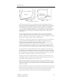
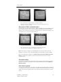
Not all motors exhibit this characteristic. It is most prevalent in smaller, high efficiency motors
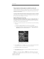
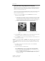
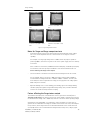
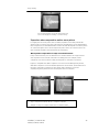
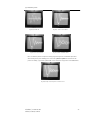
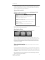
with small air gaps. Separation of wave patterns that are due to rotor coupling can be
determined when the wave patterns separate from the first positive peak downward, cross
one another at the bottom (first most negative point) and separate again as they go upward
(positive).
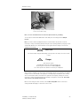
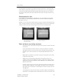
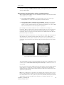
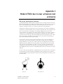
Fig 5-22 Wave pattern comparisons for motor with rotor in place.
The recommended procedure for testing assembled motors when rotor coupling may occur is
as follows. Refer to Three Phase Motor Surge Test and Set-Up for detailed instructions for
surge testing.
If the rotor cannot be turned, carefully observe the wave pattern as the test voltage is slowly
raised. Watch for a sudden shift to the left, instability or flickering which would indicate a
winding fault. Many winding insulation failures will not be visible at low voltages but become
apparent at a higher voltage.
Note: Rotor coupling does not impede the surge impulse from stressing the turn-to-turn or
phase-to-phase insulation. It only causes the rapid damping of the wave pattern. The surge
test can still detect turn-to-turn or phase-to-phase shorts. Unstable, flickering wave patterns
clearly indicate a fault in assembled motors whether rotor coupling is present or not.
12/2/2009 | 71-002-V5 EN
ST103A, ST106A, ST112A
52