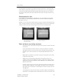
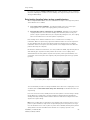
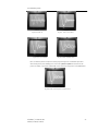
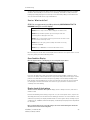
Download 5 - Advanced Test Equipment Rentals
Transcript
® E stablished 1981 Advanced Test Equipment Rentals www.atecorp.com 800-404-ATEC (2832) User’s Manual Surge/DC HiPot/Tester Models ST103A/ST106A/ST112A ST203A/ST206A/ST212A Baker Instrument Company, an SKF Group Company 4812 McMurry Avenue Fort Collins, CO 80525 (970) 282-1200 (970) 282-1010 FAX (800) 752-8272 USA Only 12/2/2009 | 71-002-V5 EN ST103A, ST106A, ST112A 1 Warranties; Disclaimers Limited Warranty as to Baker/SKF Brand Products. 1) Baker/SKF warrants that Baker/SKF brand Products, if any, that are sold under the Agreement shall be of the kind and quality described in Baker/SKF's acknowledgment of Buyer's Order, and shall be free of material defects in workmanship and material for a period from the date of shipment equal to (i) twelve (12) months in the case of new Products (including factory-installed circuit boards, accessories and options purchased concurrently with the applicable Product), (ii) six (6) months in the case of used or refurbished Products, and new circuit boards, accessories and options delivered separately from the applicable Product, (iii) a period of ninety (90) days from the date of shipment in the case of used or refurbished circuit boards. If any such Product , accessory or option is not as warranted, Buyer must notify Baker/SKF thereof in writing within the applicable warranty period. 2) Baker/SKF's sole obligation, and Buyer's sole remedy, under the foregoing warranty shall be to provide the parts and labor for the repair or replacement (at Baker/SKF's sole option) of defective parts, recalibration of any portions of a product that could reasonably have been affected by the repair, and functional verification to affirm proper operation. When, subject to the next sentence, the Buyer returns Products, accessories or options to the Baker/SKF factory for warranty service, Baker/SKF will bear the cost of return packaging, and shipping , and insurance ,on the return shipment. For Products, accessories or options that Baker/SKF designates as “on-site service only” due to their size, the permanence of their installation pr otherwise, travel expenses (including labor costs for time spent traveling) for warranty services are covered to the location of original shipment and installation. Products, accessories and options that are capable of being returned to the factory for service may receive warranty service on site, but all travel expenses (including labor charges for time spent traveling) shall be the responsibility of Buyer. 3) For warranty coverage of “on-site service only” items, Buyer must make available to Baker/SKF a knowledgeable operator to assist with preliminary diagnosis prior to a service trip being scheduled. Buyer, in connection with a request for on-site service, must be capable of authorizing charges for the service visit in the event the issues discovered are not covered by warranty, such as application errors or installation errors. If Buyer, having elected to perform installations without Baker/SKF’s participation and having encountered irresolvable problems, shall be charged for an installation if on-site assistance is necessary, except when defective product is determined to be the cause. Warning: Baker Instrument Company, an SKF Group Company assumes no liability for damages consequent to the use of this product. No part of this document may be reproduced in part or in full by any means such as photocopying, photographs, electronic recording, videotaping, facsimile, etc., without written permission from Baker Instrument Company, an SKF Group Company, Fort Collins, Colorado. 12/2/2009 | 71-002-V5 EN ST103A, ST106A, ST112A 2 Table of Contents Warranties; Disclaimers....................................................................................................................... 2 Limited Warranty as to Baker/SKF Brand Products. .................................................................... 2 1.......................................................................................................................................................................... 7 PREFACE ........................................................................................................................................................... 7 Important safety information..................................................................................................................... 7 General Safety Precautions................................................................................................................. 7 Safety term definition .......................................................................................................................... 7 Other Important Safety warnings ....................................................................................................... 7 Power Source Precautions .................................................................................................................. 8 Ground the product.............................................................................................................................. 8 Operation notes .................................................................................................................................... 8 Symbols on equipment ........................................................................................................................ 9 Other Information........................................................................................................................................ 9 Cleaning & decontamination ............................................................................................................... 9 Technical assistance / Authorized Service Centers ........................................................................... 9 Intermittent operation limits ............................................................................................................... 9 Installation requirements..................................................................................................................... 9 Unpacking the unit ............................................................................................................................... 9 Power and utility ................................................................................................................................10 Environmental ....................................................................................................................................10 Storage (indoor/outdoor) ...................................................................................................................10 Shipment.............................................................................................................................................10 2........................................................................................................................................................................11 INSTRUMENT OVERVIEW ............................................................................................................................11 Front panel controls ..................................................................................................................................11 3........................................................................................................................................................................15 TEST PROCEDURES AND VOLTAGES........................................................................................................15 General user cautions and notices..........................................................................................................15 Initial tester power-up and check-out .............................................................................................15 Recommended voltages.....................................................................................................................16 Recommended Standards .................................................................................................................17 4........................................................................................................................................................................19 DC HIPOT TESTING.......................................................................................................................................19 Principles of DC High-Potential (HiPot) testing ....................................................................................19 Other Important Safety warnings .....................................................................................................21 7) Repair Parts Warning : Defective, damaged, or broken test leads must be replaced with factory-authorized parts to ensure safe operation and maintain performance specifications. ..21 DC HiPot test and set-up ..................................................................................................................22 HiPot overcurrent trip........................................................................................................................24 HiPot application tips .........................................................................................................................24 Resistance temperature compensation............................................................................................25 5........................................................................................................................................................................27 SURGE TESTING ............................................................................................................................................27 Principles of Surge testing .......................................................................................................................27 Other Important Safety warnings .....................................................................................................28 17) Repair Parts Warning : Defective, damaged, or broken test leads must be replaced with factory-authorized parts to ensure safe operation and maintain performance specifications. ..29 Surge comparison testing..................................................................................................................29 Examples of Surge comparison testing ............................................................................................30 Surge comparison testing against a standard or master coil ........................................................31 Single coil Surge test and set-up .....................................................................................................31 Three phase motor Surge comparison test and set-up .................................................................33 Surge voltage measurement.............................................................................................................34 Notes for Surge and Surge comparison tests .................................................................................35 Factors affecting the Surge testers output......................................................................................35 12/2/2009 | 71-002-V5 EN ST103A, ST106A, ST112A 3 Table of Contents Determination of a fault ....................................................................................................................37 Good, stable trace ..............................................................................................................................37 Instability.............................................................................................................................................37 Separation when compared to another wave pattern ....................................................................38 Wave pattern separation for Wye-connected motors.................................................................38 Fault location for Wye-connected three phase motors ..................................................................39 Wave pattern separation for Delta-connected motors...................................................................39 Winding fault location for Delta-connected three phase motors...................................................40 Open circuit.........................................................................................................................................40 Open phase in Wye-connected motors ............................................................................................40 Open phase in Delta-connected motors ..........................................................................................41 Grounded winding ..............................................................................................................................41 Hard short to ground.........................................................................................................................41 Partial short to ground ......................................................................................................................42 Wye-connected motors....................................................................................................................42 Delta-connected motors ..................................................................................................................42 Surge test applications .............................................................................................................................42 Maintenance testing...........................................................................................................................42 Application notes........................................................................................................................................43 Single phase motors and two terminal devices...............................................................................44 Determination of a fault ....................................................................................................................44 Form coils ...........................................................................................................................................44 Determination of a fault ....................................................................................................................44 Notes and tips for form coils.............................................................................................................44 Three phase motors..................................................................................................................................45 Determination of a fault ....................................................................................................................45 Two or more single coils....................................................................................................................45 Determination of a fault ....................................................................................................................46 Notes and precautions for two single coils ......................................................................................46 Wound rotor motors ..........................................................................................................................46 Determination of a fault ....................................................................................................................47 Synchronous motor/generator ..........................................................................................................47 Determination of a fault ....................................................................................................................47 Pole piece fault ..................................................................................................................................47 Stator winding fault ..........................................................................................................................48 Chiller motor testing ..........................................................................................................................48 Field coils.............................................................................................................................................48 DC motor/generators .........................................................................................................................48 Armatures...........................................................................................................................................48 Bar-to-bar Surge test .......................................................................................................................48 Span testing........................................................................................................................................49 Determination of a fault ....................................................................................................................50 Notes and tips on span testing armatures ......................................................................................50 Testing large AC stator motors.........................................................................................................51 Notes and tips for large AC stator/motors....................................................................................51 Rotor loading (coupling) when testing assembled motors ..................................................................52 Testing assembled motors from the switchgear ..................................................................................53 Notes and tips for testing from the switchgear ...........................................................................53 Transformers......................................................................................................................................54 Single phase transformers ................................................................................................................54 Three phase transformers.................................................................................................................54 Determination of a fault ....................................................................................................................55 6........................................................................................................................................................................57 ADDITIONAL TESTS ......................................................................................................................................57 Other Important Safety warnings .....................................................................................................57 27) Repair Parts Warning : Defective, damaged, or broken test leads must be replaced with factory-authorized parts to ensure safe operation and maintain performance specifications. ..58 12/2/2009 | 71-002-V5 EN ST103A, ST106A, ST112A 4 Table of Contents Polarization Index test (PI) ................................................................................................................58 Polarization Index test evaluation.....................................................................................................58 Step-Voltage test ...............................................................................................................................58 APPENDIX A....................................................................................................................................................61 TYPICAL WINDING FAULTS .........................................................................................................................61 APPENDIX B ...................................................................................................................................................63 TROUBLESHOOTING.....................................................................................................................................63 Self help and diagnostics ...................................................................................................................63 Step #1: Basic information..............................................................................................................63 Step #2: Applications or service problem?.....................................................................................63 Applications: What to do first!..........................................................................................................63 Service: What to do first!..................................................................................................................65 Open Condition Display ......................................................................................................................65 Display check of dual pattern............................................................................................................65 HiPot display checks...........................................................................................................................66 HiPot trip check ..................................................................................................................................66 Open ground check ............................................................................................................................66 Limited output Surge waveform .......................................................................................................67 Warranty return .................................................................................................................................67 Warranty return form........................................................................................................................68 APPENDIX C....................................................................................................................................................69 MODEL AT101 BAR-TO-BAR ARMATURE TEST ACCESSORY ..............................................................69 Bar-to-bar armature test accessory ...............................................................................................69 Operation ....................................................................................................................................................70 Determination of a fault ....................................................................................................................71 Application recommendations..................................................................................................................72 AT101 specifications..........................................................................................................................72 APPENDIX D ...................................................................................................................................................73 TECHNICAL SPECIFICATIONS......................................................................................................................73 Technical specifications......................................................................................................................73 INDEX...............................................................................................................................................................75 12/2/2009 | 71-002-V5 EN ST103A, ST106A, ST112A 5 Table of Contents 12/2/2009 | 71-002-V5 EN ST103A, ST106A, ST112A 6 1 Preface Important safety information General Safety Precautions Note: The general safety information presented here will be for both operating and service personnel. Specific warnings and cautions will be found throughout this manual where they apply. Note: If the equipment is used in any manner not specified by Baker Instrument Company, an SKF Group Company, the protection provided by the equipment may be impaired. Safety term definition DANGER: Indicates a hazardous situation which, if not avoided, will result in death or serious injury. WARNING: Indicates a hazardous situation which, if not avoided, could result in death or serious injury. CAUTION: Indicates a hazardous situation, which, if not avoided, could result in minor or moderate injury. NOTICE: “NOTICE” is the preferred signal word to address practices not related to personal injury. Danger High Voltage To prevent serious injury or death: - Do not use in explosive atmospheres. Do not contact test leads or device being testing while test is in progress or during discharge period. - Do not connect test leads to live circuits. Read and follow safety precautions and safe operating practices in operator manual. Do not exceed maximum operating capabilities of this instrument. Other Important Safety warnings Failure to follow these precautions could result in severe electrical shock or death. 1) Never attempt a two-party operation. Always know what test is being performed and when. FOR EXAMPLE: DO NOT adjust test leads when footswitch is being operated. Leads will have live voltage and severe electric shock may result. 2) For capacitor-started motors or systems with surge arrestors/power factor capacitors, be sure to disconnect all capacitors from the test circuit before testing. 12/2/2009 | 71-002-V5 EN ST103A, ST106A, ST112A 7 Safety Precautions & Notices 3) Upon completion of a DC High Potential, Megohm, Polarization Index, Dielectric absorption, before disconnecting the test leads, short the winding, motor, etc., to ground and allow time for discharge. If this is not done, voltage may still be active on leads and tested components. 4) Make sure the tester leads are disconnected before the motor is energized or powered up. 5) Do not remove the product covers or panels or operate the tester without the covers and panels properly installed. Components on inside of tester carry voltage for operation and if touched can render a shock. 6) Use appropriate safety equipment required by your organization, including high voltage globes and eye protection. 7) Repair Parts Warning : Defective, damaged, or broken test leads must be replaced with factory-authorized parts to ensure safe operation and maintain performance specifications. 8) Ground the product : This product is grounded through the grounding conductor of the power cord. To avoid electrical shock, plug the power cord into a properly wired/grounded receptacle before connecting the product test leads. a. 9) Danger from loss of ground – Upon loss of the protective ground connection, all accessible conductive parts, including knobs and controls that may appear to be insulated, can cause an electric shock! This instrument is NOT waterproof or sealed against water entry. 10) The unit is for indoor use. If used outdoors, the unit must be protected from rain, snow and other contaminants. Power Source Precautions This product is intended to operate from a power source that does not apply more than nominal 120 volts RMS (ST103/ST106/ST112) or nominal 240 RMS (ST203/ST206/ST212) between the supply conductor or between either supply conductor and ground. A protective ground connection by way of the grounding conductor in the power cord is essential for safe operation. Ground the product This product is grounded through the grounding conductor of the power cord. To avoid electrical shock, plug the power cord into a properly wired receptacle before connecting the product test leads. Operation notes − − − Irregularities, particularly vertical peaks, may be seen in the first cycle of the wave pattern. These occur most frequently on large, high voltage motors. Do not interpret these as faults in the winding. Any winding fault will be seen through the entire wave pattern. Do not change the Test Lead Select, if so equipped, switch setting during a test. When increasing the applied voltage, switch to a higher Volts/Div setting so the entire wave pattern remains visible on the display. 12/2/2009 | 71-002-V5 EN ST103A, ST106A, ST112A 8 Safety Precautions & Notices − Always return the Output Voltage control to Min when a test is complete. Begin each test at the Min voltage setting. Failure to do so may result in damage to the test winding and/or the tester. Symbols on equipment Protective conductor terminal. Located beside black ground test lead on front panel of instrument. Earth (ground) terminal Frame or chassis terminal. Located on rear panel of instrument by ground terminal. Warning about hazardous voltage and risk of severe electrical shock or death. Located beside each red test lead on front panel of instrument. Other Information Cleaning & decontamination The ST103A, ST106A, or ST112A should be kept clean and in a dry environment. To clean the unit, power down and unplug the instrument. Wipe with a clean water dampened cloth. Do not submerge in water or other cleaners or solvents. To clean the screen, take a soft water dampened cloth and gently wipe the surface. Technical assistance / Authorized Service Centers See our website at www.bakerinst.com for technical assistance/authorized service center information. This information will be marked with an asterisk. Intermittent operation limits At this time there are no intermittent operation limits to the use of the AWA unit. Installation requirements The unit may be operated 1) 2) 3) Flat on the bottom of the unit, Flat on the back of the unit, or Held at an angle using the rotating handle. There are no ventilation requirements. The unit is intended for use in Installation Category II (Portable Equipment) areas and pollution Degree II Environments where occasional non-conducting condensing pollution can be encountered. Unpacking the unit Carefully remove the following items from the shipping boxes. ST103A, ST106A or ST112A Power cord 12/2/2009 | 71-002-V5 EN ST103A, ST106A, ST112A 9 Safety Precautions & Notices Users Manual Power and utility Input power must be 110 to 120 VAC at 60 Hz for the ST103/ST106/ST112A (220 to 230 VAC at 50 Hz (single phase source only) for the ST203/ST206/ST212). Please be aware that fluctuations in input voltage will affect output voltages and calibration. Environmental The tester should only be operated in temperatures ranging from 0 to 100 degrees Fahrenheit (-17.8 to 37.8 degrees Celsius). As with all insulation dielectric and resistivity measurements, humidity will affect the condition of the instruments components over time. Relative humidity of the storage environment should be less than 50 percent. Storage (indoor/outdoor) This instrument should not be stored in any location where water entry to the instrument could occur. Also, humidity will affect the operation of the instrument. Shipment All Baker testers are shipped using factory foam-filled containers. Should the tester be returned to Baker Instrument Company, an SKF Group Company for any reason, we recommend using the original packaging the unit came in or the following factory specified packaging: Contact Baker Instrument Company, an SKF Group Company to order factory-specified packaging for your testers. 12/2/2009 | 71-002-V5 EN ST103A, ST106A, ST112A 10 2 Instrument overview Fig 2-1 A-Series Front Panel Diagram Front panel controls 1) Cathode ray tube The Cathode Ray Tube (CRT) or display is the location where HiPot and surge test results are displayed. It is divided into a grid (graticules) for easy reference when examining waveforms and HiPot data. 2) Line in The external AC power supply plug wire is inserted here. 3) On/off The On/Off switch contains a circuit breaker and a green On indicator lamp. 4) Focus Rotate this control to adjust the clarity of the trace on the display – from a wide, thick line to a narrow, fine line. 5) Intensity This control will adjust the intensity or brightness of the display. Clockwise (CW) will increase intensity. Counterclockwise (CCW) will decrease intensity. Intensity has a slight effect on the focus. It can be adjusted to a blank screen. 6) Horizontal position Rotate this control to adjust the side-to-side position of the surge wave pattern. A trace that begins at the far left is suggested for surge testing. 7) Vertical position This control adjusts the up or down position of the surge wave pattern. The optimum positioning is usually on center or one major graticule line below center for the surge test. Two or more graticule lines below center is usually optimum for the HiPot test. 8) Sweep The sweep adjusts the seconds per division, or sweep rate, or the trace on the display. This control will have the effect of expanding or contracting the wave pattern when surge testing. 12/2/2009 | 71-002-V5 EN ST103A, ST106A, ST112A 11 Instrument Overview There are six markings corresponding to 5, 10, 20, 50, 100, and 200 microseconds per division. The lower values represents the slowest rate and higher numbers represent the fastest. Markings on the face panel indicate approximate sweep rates. The sweep rate is not calibrated and should be used for indication only. NOTICE During the surge test, with the SWEEP control at the lowest possible setting, the ringing pattern must be at least one division in length for one full cycle. Less than one division for the first cycle indicates a very low inductive load. DAMAGE to the instrument is possible when operated for an extended period of time with a low inductive load. 9) Function selector This control selects the type of test to be performed and the sensitivity of the DC HiPot leakage current display. There are four primary positions as follows: − − − Surge – This position selects the Surge Test. HiPot – Micro-Ampship/Div – These three positions are used for the DC HiPot test and the sensitivity of the display on the CRT. The three positions are 100, 10, and 1 microamps per division. It also automatically selects the auto-ranging overcurrent trip point which will be ten times these settings, or 1000, 100, and 10 microamps respectively. Aux – The auxiliary position is for use with Baker Instrument Company, an SKF Group Company’s AT 101 Bar-to-Bar Armature Testing Accessory or a 24 kV Power Pack (12 kV testers only) (see Appendix E: Models AT101 Bar-to-Bar Armature Test Accessory and Appendix D: PP124/PP224 Power Pack). The display will also show wave patterns from accessory units in this position. Note: The Zero Start Interlock is disabled when this function is selected. 10) Volts/div This control sets the sensitivity of the display or scale factor in volts per division for both the surge and HiPot test traces. There are four settings corresponding to 250, 500, 1000, 2500 volts per division. Note: The volts/Division setting values may not be valid using some accessories. Note: This control does not affect or limit the output voltage of the tester! 11) Open ground warning light When the AC line source is not properly grounded, this red Open Ground light will illuminate. The test set will power up, but high-voltage will be held inoperative by the internal electronics. (See Appendix B: Troubleshooting, for more information). 12) HiPot trip warning light This lamp will light to indicate the DC HiPot trip circuit has stopped the test. The red lamp will stay illuminated and high voltage output will be disabled until the Test (16) button is released 13) HiPot current select switch and light (12kV testers only) This push-button and indicator light combination on ST112 and ST212 testers selects either Internal or External HiPot display functions. This switch has two positions as follows: 12/2/2009 | 71-002-V5 EN ST103A, ST106A, ST112A 12 Instrument Overview − − Internal – For stand alone operation of the tester, this button should be in the “out” position, with its indicator light off. The unit will then display Internal HiPot readings of voltage and leakage current taken from the testers own test leads. External – When this button is depressed and the indicator light is on, the display will show the readings of HiPot readings obtained from external units, such as a 24 kV Power Pack (See Appendix D: PP124/PP224 Power Pack). 14) Leads energized indicator light The indicator will light when voltage is applied during a test. 15) Output control This control adjusts the output voltage of the tester. Clockwise (CW) rotation increases output and counterclockwise (CCW) rotation decreases output. Full CCW is the MIN point or zero output and full CW is MAX or 100% of the testers rated output. Note: A Zero Start Interlock is used with this control during surge and HiPot tests. The user must return the Output Control to MIN for each test. In other words, if the Test button is pressed while the Output Control is rotated above MIN the testers output is disabled until the Output Control is rotated to MIN. The Zero Start Interlock is disabled for AT101 testing. NOTICE When testing a highly inductive coil (high turns counts), it is possible to develop voltages in excess of the testers rated output. Damage may occur to the tester. Use caution to limit the output to no more than the instruments rating. Monitor the voltage by observing the display. 16) Test The Test button activates the high voltage output of the tester. One of the selected modes, surge or HiPot, will be enabled and a voltage will be impressed on the device being tested. This button automatically disengages when released. 17) Test Lead Select (TLS) This is a high voltage rotary switch that selects which test lead will be Hot or energized, which are Open during HiPot tests, and which are to be a Ground. − Settings 1-2, 2-3, 3-1 are for surge testing. The red Test Leads (20) are numbered and correspond to these settings. The lead number setting indicates which test leads are Hot or energized. − The HiPot position energizes test lead #1 and opens test leads #2 and #3. − The Leads Ground • position holds all three red leads at the same grounded potential as the black Ground lead. It is a safety feature that should always be used whenever the operator touches the testers leads to change their position. Use the chart below as a reference for TLS positions and lead potential. 12/2/2009 | 71-002-V5 EN ST103A, ST106A, ST112A 13 Instrument Overview Test lead connections Switch Position TLS 1-2 TLS 2-3 TLS 3-1 HiPot All Leads Ground Test Lead #1 Test Lead #2 Test Lead #3 Hot Ground Hot Hot Ground Hot Hot Ground Open Ground Ground Hot Hot Open Ground Test Lead Ground Ground Ground Ground Ground Ground 18) Auxiliary port The auxiliary port is used for using the surge tester with the PP124/PP224 24 kV Power Pack, for high voltage testing, or the AT 101 Bar-to-Bar Armature Test Accessory. (Refer to Appendix D: P124/PP224 Power Pack and Appendix E: Model AT101 Bar-to-Bar Armature Test Accessory respectively). 19) Footswitch connector A footswitch may be connected to this socket which is in parallel to the Test (16) switch. The footswitch will operate the tester in a manner identical to the Test switch, freeing the users hands from having to operate the switch. 20) Test leads The red test leads #1, #2, and #3 and the black ground lead marked • are provided or contact to the windings. Test leads are insulated to 45 kV. 12/2/2009 | 71-002-V5 EN ST103A, ST106A, ST112A 14 3 Test procedures and voltages Throughout this manual, Baker Instrument Company, an SKF Group Company will recommend various procedures that should be followed for the most efficient and safe use of your tester. These procedures have been developed through constant feedback from you, the user. Baker Instrument Company, an SKF Group Company recommends that you perform the DC HiPot test first, in order to determine if a windings ground wall insulation has failed. If this occurs, it is not necessary to proceed with any further testing – the winding is bad. If the test piece passes the DC HiPot test, it is then appropriate to proceed with the Surge test. General user cautions and notices − − − − − − − − − Always unclip the test leads. Do not jerk or pull them from the motor leads! Never connect test leads from two or more testers on the same load. This includes connection of host and power pack unit leads to the same load. This warning also includes lead connections, even for grounding purposes. Irregularities, particularly vertical spikes, are sometimes seen in the first cycle of the surge wave pattern. These occur most frequently on large, high voltage motors (refer to Testing Large AC Stators/Motors). Do not interpret these as faults in the windings. Any winding fault will be seen throughout the entire wave pattern. Do Not change the Test Lead Select (TLS) switch setting while a test is being made. Doing so will cause arcing and damage the switch contacts, resulting in improper operation and accelerated aging of the instruments components. The divisions on the CRT display are the heavy graticules (lines) that are etched on the screen approximately one centimeter apart. For the Volts/Div and Micro-Amps/Div controls, the divisions referred to are these divisions. Note that there are five small segments marked per main vertical and horizontal division. Do not turn the Function switch between Surge and HiPot settings during testing. It is only acceptable to alter HiPot current settings while in the HiPot mode. When increasing the applied voltage during a test, use a higher Volts/Div setting so the entire wave pattern or trace stays visible on the screen. It is acceptable to change this setting while testing. The Volts/Div control has no effect and does not limit the output voltage of the tester. It only controls the display scale. The surge tester is equipped with a Zero Start Interlock assembly that requires the return of the Output control to MIN (zero) before the start of each test. It is not uncommon to see separation of compared wave patterns with newer models when the same comparison may show no separation on an older surge tester. Baker Instrument Company, an SKF Group Company testers often show separation caused by concentric (basket) winds and capacitance or magnetic imbalances. Care should be taken when interpreting slight separations seen when Surge Comparison testing. Initial tester power-up and check-out Note: Each Baker Instrument Company, an SKF Group Company Tester incorporates a supply ground detection circuit. This circuit assures a positive grounding of the tester. If the instrument is not properly grounded, the Open GRD indicator will light and testing cannot proceed. Check the supply to the tester (broken ground, bad extension cord, excessive ground to neutral voltage) and assure that a low impedance ground is provided to the unit. 12/2/2009 | 71-002-V5 EN ST103A, ST106A, ST112A 15 Test Procedures, Voltages & Applicable Standards 1) Check that the On/Off switch is in the Off Position. 2) Connect the tester power cord to a 110-120 VAC outlet (or 220-240 VAC outlet for 203, 206, 212 machines). The tester will work on either 60 Hz (103, 106, 112) or 50 Hz (203, 206, 212). 3) Set the Output control to Min (fully counterclockwise). 4) Turn the tester On/Off switch to On. Allow a brief period for CRT warm-up. A display trace should appear in seconds. 5) If the CRT does not display anything, turn the unit Off immediately and recheck the steps above. Also, check that the Intensity is not turned fully counterclockwise. Turn the tester On to obtain a display on the CRT. If no display is noticed, turn the unit Off and call Baker Instrument Company, an SKF Group Company’s Service Department. Refer to Warranty Notes and Appendix B: Troubleshooting for calling information. 6) The unit is now ready for testing. Recommended voltages A recommended value for DC High Potential (HiPot) and Surge voltage to test a motor, generator, or transformer in service is twice the line voltage plus 1000 volts. This test voltage value is consistent with NEMA MG-1, ANSI/IEEE 95-1977 (test voltages greater than 5000V) and IEEE 43-1974 (test voltages less than 5000V). Examples for 460 and 4160 volts motors are as follows: 2 x 460 V = 920 V + 1000 V = 1920 V 2 x 4160 V = 8320 V + 1000 V = 9320 V For new windings or rewound motors, this potential is sometimes increased by a factor of 1.2 or as much as 1.7. This provides for a higher level of quality control on the work performed. For the above 460 V motor, the test voltage may be: 1920 V x 1.2 = 2304 V or as high as 1920 V x 1.7 = 3264 V Note: Although the CRT display is accurately calibrated, it is not possible to discern small or minor voltage increments. It is suggested that the formula answers be rounded off, or more specifically, rounded to the nearest minor graticule division discernible. 12/2/2009 | 71-002-V5 EN ST103A, ST106A, ST112A 16 Test Procedures, Voltages & Applicable Standards Recommended Standards IEEE-43-1974 Recommended Practice for Testing Insulation Resistance of Rotating Machinery (Reaff 1991) IEEE-56-1977 Guide for Insulation Maintenance of Large AC Rotating Machinery (10,000 kVA and Larger) (Reaff 1991) IEEE-112-1991 Test Procedures for Polyphase Induction Motors and Generators (ISBN 1-55937-188-9) IEEE-113-1985 Guide on Test Procedures for DC Machines IEEE-115-1983 Test Procedures for Synchronous Machines (Reaff 1991) IEEE-429-1972 Evaluation of Sealed Insulation Systems for AC Electric Machinery Employing Form-Wound Stator Coils IEEE-432-1992 Guide for Insulation Maintenance for Rotating Electrical Machinery (5 hp to less than 10,000 hp) (ISBN 1-55937237-0) IEEE-434-1973 Guide for Functional Evaluation of Insulation Systems for Large High-Voltage Machines (Reaff 1991) IEEE-522-1992 Guide for Testing Turn-to-Turn Insulation on Form-Wound Stator Coils for Alternating-Current Rotating Electric Machines (ISBN 1-55937-252-4) Obtain reprints of these articles by contacting: IEEE Customer Service 445 Hoes Lane PO Box 331 Piscataway, NJ 08855-1331 Phone: 800-678-IEEE (4333) Fax: 908-981-9667 www.ieee.org 12/2/2009 | 71-002-V5 EN ST103A, ST106A, ST112A 17 Test Procedures, Voltages & Applicable Standards 12/2/2009 | 71-002-V5 EN ST103A, ST106A, ST112A 18 4 DC HiPot Testing Principles of DC High-Potential (HiPot) testing DC HiPot Testing has proved to be a useful tool to evaluate, non-destructively the dielectric strength of ground insulation. No insulation is perfect and all have some conductivity, so some current flows or “leaks” along or through the insulation to ground. By charging the winding to a specific test voltage and holding the frame at ground, leakage current can be monitored. The insulation’s resistance is an important factor in evaluating its condition. However, insulation resistance is only one factor. It has little to do with insulation'’ dielectric strength or break-over voltage. Insulation resistance can be measured and dielectric strength assured with a DC HiPot Test. The resistance is determined by dividing the voltage impressed on the coil by the leakage current measured. Both are monitored with the DC HiPot test. Determining resistance via voltage impressed and leakage current can be understood with the analogy of a water pipe. Two tests of the pipe are possible. Imagine a water pipe, which has no leaks and is capable of withstanding a maximum pressure. If a small hole is drilled in the pipe, a certain amount of water would escape and cause leakage. An increase of water pressure in the pipe would cause a measurable increase in the leakage of water, but it would not necessarily rupture the pipe. In the second test, if a pipe with no holes were worn thin and the pressure increase to test the pipes strength, at some pressure it may rupture, allowing all the water to be released. In an electrical conductor, the pipe would be an insulator and the water pressure would be the voltage impressed on it. Leakage current in the insulator would be comparable to water flowing through the hole in the pipe. As voltage is increased on the leaking insulator there would be a corresponding increase in leakage current. Higher leakage currents (a larger hole in the pipe) corresponds to lower resistance of the insulation to the flow of current. A perfect insulator (pipe with no holes) is said to have high resistance. The second test, where the pipe is subjected to rupturing, is comparable to measuring the dielectric strength or dielectric limit of the insulation. The possibility of rupturing is measured in an electrical conductor with a high potential (HiPot) test. The point of rupture is called the dielectric limit of the insulation material. In HiPot Testing, the voltage (water pressure on the pipe) is increased on the coil. However, the DC HiPot test does not breakdown the insulation. Good insulation has a dielectric strength value much higher than the operating voltage of the apparatus and common field test voltages. The HiPot Test is used to ensure that the insulation DOES NOT breakdown or rupture at a prescribed test value. The test voltage should be less than the rated dielectric strength of the insulation. If the insulation does fail under the test, the insulation to ground is unreliable and the apparatus is unusable. Knowledge of the real behavior of resistors, not just ideal resistors, will help the operator to test the winding insulation to a point before the insulation is broken down. 12/2/2009 | 71-002-V5 EN ST103A, ST106A, ST112A 19 DC HiPot Testing Fig 4.1 Principle of Resistance For an ideal resistor, good or poor, as the voltage is increased, the leakage current will increase proportionately and indefinitely (Fig 4-1). However, insulation resistance in the real world rarely behaves in this manner. Instead, the current in a typical resistor will increase proportionately with voltage until the voltage is within as little as 5% of the breakdown voltage. Just before insulation breakdown, the current will rise faster than the voltage. At still higher voltage, the insulation will completely breakdown and the current will rise extremely fast. The key to DC HiPot testing is to look for leakage current that is rising faster than the increase in voltage that is applied to the winding. The test can then be stopped before the insulation is damaged. (For more information on DC HiPot tests refer to IEEE-95-1977 which describes test procedures, voltages, safety, and interpretation.) The HiPot test is considered the mainstay of motor testing. HiPot tests can be performed in one of two ways, AC or DC. Although the Surge test will test for grounds, it does not uniformly test all the ground wall insulation as thoroughly a the HiPot test. Nor does the Surge test give a quantitative value of the leakage current to ground The HiPot brings the entire motor winding up to the same potential. Since all the windings are at the same potential, there is no turn-to-turn, or phase-to-phase insulation stress. There is uniform voltage stress applied between the winding insulation and the ground wall. As discussed before the theory behind the test is based on simple leak current. Given any good insulation, the current leakage through the insulation should be very low and therefore the insulation resistance very high, and vise versa. The formula associated with this test is R = E/I. This formula states that resistance is equal to voltage divided by current, or put another way, resistance is inversely proportional to current for a given voltage. The HiPot tester provides a voltage variable up to some limit. The resistance is that of the ground wall to ground or the motor frame. Using the formula, the higher the resistance for a given voltage, the lower the leakage current, and vise versa. Baker Instrument Company, an SKF Group Company testers provide the DC HiPot test as a separate and added function to the Surge testing unit. The Baker tester provides a variable voltage source to apply to motor windings and a state of the art CRT display for both voltage and current readings. During a typical DC HiPot test, all motor output leads are tied together and connected to test lead #1. The tester ground lead is connected to the motor frame. The output voltage is raised to some predetermined test voltage and a current reading is measured. The lower the leakage current reading for the given voltage, the better the ground wall insulation. 12/2/2009 | 71-002-V5 EN ST103A, ST106A, ST112A 20 DC HiPot Testing Danger High Voltage To prevent serious injury or death: - Do not use in explosive atmospheres. Do not contact test leads or device being testing while test is in progress or during discharge period. - Do not connect test leads to live circuits. Read and follow safety precautions and safe operating practices in operator manual. Do not exceed maximum operating capabilities of this instrument. Other Important Safety warnings Failure to follow these precautions could result in severe electrical shock or death. 1) Never attempt a two-party operation. Always know what test is being performed and when. FOR EXAMPLE: DO NOT adjust test leads when footswitch is being operated. Leads will have live voltage and severe electric shock may result. 2) For capacitor-started motors or systems with surge arrestors/power factor capacitors, be sure to disconnect all capacitors from the test circuit before testing. 3) Upon completion of a DC High Potential, Megohm, Polarization Index, Step Voltage, Dielectric absorption, or Continuous Ramp test, before disconnecting the test leads, short the winding, motor, etc., to ground and allow time for discharge. If this is not done, voltage may still be active on leads and tested components. 4) Make sure the tester leads are disconnected before the motor is energized or powered up. 5) Do not remove the product covers or panels or operate the tester without the covers and panels properly installed. Components on inside of tester carry voltage for operation and if touched can render a shock. 6) Use appropriate safety equipment required by your organization, including high voltage globes and eye protection. 7) Repair Parts Warning : Defective, damaged, or broken test leads must be replaced with factory-authorized parts to ensure safe operation and maintain performance specifications. Ground the product : This product is grounded through the grounding conductor of the power cord. To avoid electrical shock, plug the power cord into a properly wired/grounded receptacle before connecting the product test leads. 8) Danger from loss of ground – Upon loss of the protective ground connection, all accessible conductive parts, including knobs and controls that may appear to be insulated, can cause an electric shock! 9) This instrument is NOT waterproof or sealed against water entry. 12/2/2009 | 71-002-V5 EN ST103A, ST106A, ST112A 21 DC HiPot Testing 10) The unit is for indoor use. If used outdoors, the unit must be protected from rain, snow and other contaminants. DC HiPot test and set-up Note: Check the circuits to guarantee that capacitors or other devices are not connected. Not only could this be hazardous to the person performing the test, but they will also produce inaccurate measurements. 1) Turn the Function switch to one of the HiPot – Micro-Amps/Div settings. The highest scale setting is suggested. This setting defines the number of micro-amps of current measured per one graticule division on the CRT display. NOTE: Test standards recommend starting at the 100 microamp/division setting. In the event of a dead short, the fault will be readily detectable. The lowest setting gives the operator the greatest sense of understanding and control of what is occurring as the winding is being charged during the test. However, the desired test voltage can be reached faster by initially using the highest setting. The 100 setting decreases sensitivity and prevents overcurrent tripping due to charging currents. 2) Rotate the vertical control to position the trace on the CRT display to near the bottom of the screen, behind one of the graticule lines. This graticule will serve as the zero reference line. 3) Switch the Test Lead Select (TLS) to the HiPot Setting. This selects the red test lead #1 as Hot. The black lead is the Ground. Lead #2, and #3 are open. 4) Ensure the Output control is set at minimum, fully counterclockwise. 5) Check the circuits to ensure that capacitors or other devices are not connected. Not only could this be hazardous to the person performing the test, but it will also provide inaccurate results. 6) On multi-lead equipment, all equipment leads should be connected to lead #1 of the tester. Use jumpers to facilitate this procedure. Winding leads that are not connected to the testers lead #1 may be at the same or higher voltage potential as the test voltage and potentially hazardous. The other two red leads, #2 and #3 should not be connected during the HiPot test. 7) Connect the black Ground lead to a clean ground on the frame or core of the equipment under test. 12/2/2009 | 71-002-V5 EN ST103A, ST106A, ST112A 22 DC HiPot Testing Fig. 4.2 Example of how to connect the test leads to the motor for HiPot Testing Note: It is not recommended to use the motor junction box for grounding. To test, depress and hold the Test button and slowly raise the voltage with the Output Control. Note: The rate at which the Output Control is increased affects the amount of current necessary to charge the winding. Slowly raising the output (voltage) will keep charging current at low levels. Monitor the current indication on the right half of the display to observe the charging current levels. CAUTION This test should be stopped immediately, if at any time a fast sharp rise in the current is seen. Danger Use extreme caution. Completely discharge the equipment under test By moving the TLS position to “LEADS GROUND” For a time equal to the duration of the test just completed. As the voltage is applied to the motor, two horizontal lines appear on the display. The applied voltage is seen on the left half of the display as a steadily rising horizontal line. The current, also a horizontal line, will rise and fall on the right half of the display, showing the current necessary to charge the windings. Once the winding is charged the current falls. The steady state current is the leakage current level. Once the test voltage has been reached, turn the Micro-Amps/Div switch to the lowest setting that will still display a current bar on the screen. 12/2/2009 | 71-002-V5 EN ST103A, ST106A, ST112A 23 DC HiPot Testing Fig 4.3 Good insulation with high voltage and low leakage Fig 4.4 Poor insulation with low voltage 8)andMaintain the current. test potential for one ( high leakage 9) 10) 1) minute. If instability or a sharp rise in the current (right half of display) is noted, discontinue the test immediately. 11) Measure the leakage current by multiplying the number of major graticules or divisions of deflection of the trace from the zero reference line by the Micro-Amps/Div setting. Example: 2 division of deflection x 1 μamp/division setting = 2 μamp. 12) When the test is complete, release the Test button and return the Output Control to minimum. The voltage bar will gradually return to the baseline as the winding capacitance is discharged through the internal resistance of the tester. Note: The current trace will temporarily go negative as the winding discharges. Allow a sufficient time for the test winding to discharge completely. Recommended practice is to ground the leads of the test winding for a time equal to the time the test potential was applied. Baker recommends using the TLS “Leads Ground” position. (When the current trace returns to zero from its negative position, the windings are discharged.) HiPot overcurrent trip The tester is equipped with an auto-ranging HiPot over-current safety trip device. If the HiPot current levels go too high, this over-current trip will stop the test. The red HiPot Trip lamp on the front panel will light. The over-current trip point is ten (10) times the Micro-Amp/Div setting selected on the Function knob. Releasing the Test button resets the trip in which case the red HiPot Trip lamp will go off, and the unit is ready to begin testing again. Windings that are grounded will cause the current trace to quickly go off screen and the HiPot over-current trip to activate. HiPot application tips − A poor ground connection may cause a device to show no leakage current. It will appear that the device has infinite resistance to ground. This can be misleading and cause a bad motor to test as good. Note: Before beginning the DC HiPot test, the HiPot over-current safety trip may be used to verify that a good ground has been made with the black ground lead. After making the connection to the frame (ground) with the ground lead, connect red lead #1 to another point on the frame. Keep the Output Control at minimum and press the Test button. A good ground connection will activate the overcurrent trip at the slightest increase of output (trip sensitivity is affected by current setting). If the trip does not operate, reconnect the ground and repeat this test. Ensure the continuity of the ground lead. Often the paint on the device is preventing a good ground and may need to be scraped off. 12/2/2009 | 71-002-V5 EN ST103A, ST106A, ST112A 24 DC HiPot Testing − The DC HiPot test component of the tester can test the insulation between any two conductors. For example, it may be used to test the insulation between feeder cables and the ground lead on the others. Follow the same procedures outlined for HiPot Testing. Change these connections to test all cables. Resistance temperature compensation When HiPot testing, temperature and humidity will have an influence which, can distort the results. It is also important to ensure that the test pieces insulation is dry and clean. The Rule of Thumb for determining the effect of temperature on resistance measurements is that resistance halves for each 10oC (Celsius) rise in winding temperature. Usually, the baseline temperature is 40oC for windings. This rating is usually found on the motors data plate. The following two examples illustrate this relationship. Example 1: If a resistance measurement of 100 mega-ohms is taken at 30oC, the resistance should be 50 mega-ohms at 40oC (an increase of 10oC). Example 2: If a resistance measurement of 200 mega-ohms is taken at 50oC, the resistance should be 400 mega-ohms at 40oC (a decrease of 10oC). 12/2/2009 | 71-002-V5 EN ST103A, ST106A, ST112A 25 DC HiPot Testing 12/2/2009 | 71-002-V5 EN ST103A, ST106A, ST112A 26 5 Surge testing Principles of Surge testing Prior to the introduction of surge testing, the most common electrical test for motors was a low-potential test of the winding insulation to ground (or frame). This popular test is the Insulation Resistance or Meg-Ohm test. This test is adequate for testing winding insulation to ground, but it does not detect failures between turns or phases. A more thorough test is the Surge Test. A typical motor coil consists of copper wire turns or windings. Motor winding insulation failure often starts as a turn-to-turn, copper-to-copper, or winding-to-winging fault. Surge Tests can detect the early stages of insulation failures in the winding such as a coil-to-coil failures, short circuits, grounds, misconnections, and wrong turn counts without permanently damaging the winding. Brief voltage surges (or pulses) are applied to the coil during a Surge Test to create a voltage gradient (or potential) across the length of the wire in the winding. This gradient produces a momentary voltage stress between turns. The coil will respond, in the time periods between pulses, with a ringing or damped sinusoidal waveform pattern. Each coil has its own unique signature ringing or wave pattern which can be displayed on a CRT display screen. Fig 5.1: Example of a “ringing” wave pattern resulting from Surge Testing The wave pattern observed during a Surge Test is directly related to the coils inductance. (There are other factors influencing the wave pattern but inductance is the primary one.) The coil becomes one of two elements in what is known as a tank circuit – a LC-type circuit made up of the coils inductance (L) and the surge testers internal capacitance (C). Inductance (L) of a coil is basically set by the number of turns in a winding and the type of iron core it rests in. The frequency of the wave pattern is determined by the formula: Frequency = 1 2π LC This formula implies that when the inductance decreases, the frequency will increase. A surge test can detect a fault between turns that is due to weak insulation. If the voltage is greater than the dielectric strength of the turn insulation, one or more turns may be shorted out of the circuit. In effect, the number of turns in the coil is reduced. Fewer working turns reduces the inductance of the coil and increased the frequency of the ringing pattern from the surge. 12/2/2009 | 71-002-V5 EN ST103A, ST106A, ST112A 27 Surge Testing The voltage or amplitude of the surge wave pattern is also reduced due to the decrease in inductance of a coil with a fault between turns. It is determined by the formula: Voltage = L di dt Where the current (i) varies according to pulse time (t) When the insulation between turns is weak, the result is a low energy arc-over and a change in inductance. When this happens the wave pattern becomes unstable – it may shift rapidly to the left and right, and back to the original position. A reduction in inductance occurs due to turn-to-turn faults, phase-to-phase faults, misconnections, open connections, etc. Partial ground wall testing is also performed in a surge test when there is a ground line to the machine frame. The Surge Test is most often used to test turn-to-turn insulation of coils or single windings. Form coils, start and run windings, and multi-tapped windings are a few examples. Surge Tests are also used to compare new windings to a standard winding to assure they conform. Danger High Voltage To prevent serious injury or death: - Do not use in explosive atmospheres. Do not contact test leads or device being testing while test is in progress or during discharge period. - Do not connect test leads to live circuits. Read and follow safety precautions and safe operating practices in operator manual. Do not exceed maximum operating capabilities of this instrument. Other Important Safety warnings Failure to follow these precautions could result in severe electrical shock or death. 11) Never attempt a two-party operation. Always know what test is being performed and when. FOR EXAMPLE: DO NOT adjust test leads when footswitch is being operated. Leads will have live voltage and severe electric shock may result. 12) For capacitor-started motors or systems with surge arrestors/power factor capacitors, be sure to disconnect all capacitors from the test circuit before testing. 13) Upon completion of a DC High Potential, Megohm, Polarization Index, Step Voltage, Dielectric absorption, or Continuous Ramp test, before disconnecting the test leads, short the winding, motor, etc., to ground and allow time for discharge. If this is not done, voltage may still be active on leads and tested components. 12/2/2009 | 71-002-V5 EN ST103A, ST106A, ST112A 28 Surge Testing 14) Make sure the tester leads are disconnected before the motor is energized or powered up. 15) Do not remove the product covers or panels or operate the tester without the covers and panels properly installed. Components on inside of tester carry voltage for operation and if touched can render a shock. 16) Use appropriate safety equipment required by your organization, including high voltage globes and eye protection. 17) Repair Parts Warning : Defective, damaged, or broken test leads must be replaced with factory-authorized parts to ensure safe operation and maintain performance specifications. 18) Ground the product : This product is grounded through the grounding conductor of the power cord. To avoid electrical shock, plug the power cord into a properly wired/grounded receptacle before connecting the product test leads. Danger from loss of ground – Upon loss of the protective ground connection, all accessible conductive parts, including knobs and controls that may appear to be insulated, can cause an electric shock! 19) This instrument is NOT waterproof or sealed against water entry. 20) The unit is for indoor use. If used outdoors, the unit must be protected from rain, snow and other contaminants. Surge comparison testing The results of Surge Tests can be used to compare individual motor or windings in order to detect faults. This is Surge Comparison Testing. Because the wave pattern of a Surge Test is unique to the coil being tested (due to its unique number of turns, type of wire and insulation, orientation, etc) wave patterns of supposedly identical coils should also be identical. Any difference in the coil (more or less turns, insulation break-down, orientation, etc.) would result in a different wave pattern during the Surge Test. These differences are most often due to a fault in the winding. Three-phase motors provide an illustration of Surge Comparison Testing. A typical threephase motor is assumed to be made of three identical coils or phases. Therefore, the results of three equal Surge Tests on each phase of the motor should be identical. If there are any differences in the three results, one or more of the phases may contain a fault. The A Series Tester provides a means for observing very small differences in Surge Tests, making it very sensitive to any faults in the windings. The tester does this by simultaneously superimposing the wave patterns of two Surge Tests. − When the wave pattern of two equal voltage Surge Tests are displayed simultaneously, if a single wave pattern is seen, the phases being tested are equal in their inductance. In other words the phased or windings have the same number of turns, insulation, orientation, etc. and are considered to be good. − When the wave patterns of two equal voltage Surge Tests are displayed simultaneously, if two distinct wave patterns are seen, the phases being tested are not equal in their inductance. There probably is a fault in one of the windings or there is some other cause for the differing inductance. For example, the faulted winding may have shorted turns compared to the complete phase, reducing the inductance, and thus altering the wave pattern. (An exception would occur as in the case for Rotor Loading as described later.) 12/2/2009 | 71-002-V5 EN ST103A, ST106A, ST112A 29 Surge Testing An example of Comparison Testing can be applied to newly manufactured or rewound motors which may contain an occasional error in the winding turn counts. If the error is more turns placed in one phase, the inductance becomes greater and frequency of the wave pattern becomes lower. The results of a Surge Test of the new faulty motor would be compared to the Surge Test of a standard motor which is known to have the correct number of turns. The difference in winding turns will be evident because the wave patterns will differ. Examples of Surge comparison testing Surge comparison testing is most easily applied and understood by using a stator from a three phase, lap wound induction motor as an example. When all three phases in a good motor are wound identically, comparing the phases will show the same single wave pattern. Fig 5-2: Good Comparison Pattern. Only one wave appears on the surge tester screen when two tests are displayed simultaneously. (The wave patterns being compared are superimposed exactly.) When one of the phases has a fault, one of two things will be seen on the tester. (See Fig 53.) − The wave pattern may become erratic during the test, indicating intermittent shorting in the winding and arc-over (left example in Fig 5-3). − The wave pattern for the faulted phase may appear stable, but when it is compared to the wave pattern of another good phase, it will be slightly different in comparison (right example in Fig 5-3). This is indicative of a fault in the phase associated with the differing wave pattern. Usually, this wave pattern is decreased in amplitude and has a lower frequency which shifts it toward the left. Fig 5-3: Faulty Surge Patterns: Waveforms are erratic during the test (left) or separated throughout the entire trace (right). 12/2/2009 | 71-002-V5 EN ST103A, ST106A, ST112A 30 Surge Testing Surge comparison testing against a standard or master coil Standards testing using a surge test is a surge comparison test. A coil or winding that is know to be good is selected as a standard. The standard is then connected to one of the testers two hot leads and to a ground lead. All unknown coils or windings are connected, in turn, to the remaining hot lead and ground. The surge tester will simultaneously display the surge wave patterns of both coils or windings on the display. If they are the same, the patterns will superimpose and appear to be one wave pattern. If the test coil or winding is not the same as the standard, due to a fault or arcing in the coil, two wave patterns will appear on the screen. Single coil Surge test and set-up Note: Check to ensure there is nothing connected to the coil or winding being tested. This is extremely important when testing installed coils or windings. If something other than the test winding is connected to the tester, the result will be test inaccuracies. This situation can also be hazardous to personnel performing the tests. 1) With the Test Lead Select (TLS) switch in the Leads Ground position, make the following connections. a) b) Connect the red #1 and #2 leads on one side of the coil or winding. Connect test lead #3 to the opposite side of the two terminal device. Connect the ground lead to the frame or metal core material. (Refer to Single Coil Surge Test and Set-Up on page 49 for detailed instruction.) Fig 5-4: Example of how to connect the test leads for a surge test on a single coil or 2) Turn the Function switch to the Surge position. The surge display should be blank with a horizontal line centered in it. This line is the reference zero or base line. 3) Select TLS position 1-2. These leads will be Hot. 4) Set the Volts/Div switch at the lowest setting that will allow the maximum pattern to be viewed entirely on the screen. Example: For a test voltage of 2000 V, a Volts/Div setting of 500 will give a wave pattern with 4 divisions of amplitude that does not go off the screen. For a test voltage of 4000 V, a 12/2/2009 | 71-002-V5 EN ST103A, ST106A, ST112A 31 Surge Testing setting of 500 Volts/Div would result in a wave pattern with 8 divisions amplitude which would go off the screen. 5) Testing may now begin in the following manner: a) Set the Output Control to minimum by rotating it fully counterclockwise (CCW). b) Depress and hold the Test button (or Footswitch). The Leads Energized light will come on, indicating that the test leads are hot. c) Slowly raise the Output, applying voltage to the test windings. Carefully monitor the trace on the display and adjust the Volts/Div and Sweep controls to get the best waveform possible. d) Adjust the Output and Volts/Div controls to the desired voltage level while maintaining a fully visible wave pattern on the display. The voltage is measured from the zero line to the first positive peak (at the far left) of the trace multiplied by the displayed Volts/Div setting. First Zero Line e) When the test for the lead is complete, the Test button may be released. Return the Output to minimum. The Lead Energized light will turn off. If the surge wave pattern appears steady and stable, the winding insulation is sufficient to withstand the applied voltage and the test is successful. Note: If the wave pattern begins to flicker or rapidly shift left and right and/or up and down as the Output is increased, there is weakness in the winding insulation and intermittent arcing between the windings or phases. The winding or phase contains a fault when the wave pattern shift to the left and the amplitude drops. The more severe the shift and amplitude drop, the more severe the fault. Faults are often accompanied by an audible arcing sound. When an obvious fault is present, the motor is bad. End the test by releasing the Test button and disconnecting the motor from the tester. 6) Reverse the test leads on the coil. In other words, connect test leads #1 and #2 to the other side of the coil and test lead #3 and ground to the opposite side. This is done to shoot the coil in the opposite direction. 7) Repeat Step 5, bringing the peak voltage to the same value used in the first test. In summary, for each direction the coil is tested, you will check the display for the wave pattern produced in each test. If you see stable patterns, the winding is good. If you see anything other than good patterns there is a possible fault. Refer to Determination of a Fault for explanations of wave patterns indicating good or faulty windings. Refer to Surge Test Applications for descriptions of wave patterns for a variety of devices. Keep in mind, fault determination is often a result of experience. 12/2/2009 | 71-002-V5 EN ST103A, ST106A, ST112A 32 Surge Testing Three phase motor Surge comparison test and set-up Note: Check to ensure there is nothing connected to the coil or winding being tested. This is extremely important when testing installed coils or windings. If something other than the test winding is connected to the tester, the result will be inaccuracies. This situation can also be hazardous to personnel performing the tests. The motor can be tested remotely through feeder cables (or a motor control center), however; it must be a direct path. No other electrical elements can be in the path such as surge arrestors or power factor capacitors. 1) With the Test Lead Select (TLS) switch in the Leads Ground position, make the appropriate connection as follows: a) b) Connect all three red test leads to the motor input leads. Any order is fine but Baker Instrument Company, an SKF Group Company recommends test lead #1 to motor output lead #1, #2 to #2, and #3 to #3. Refer to the chart Test Lead Connections (page 25) to know which leads will be tested for any given TLS switch position. Connect the black Ground lead to the frame or housing of the motor. Fig 5-5: Examples of how to connect test leads for three phase motor surge testing. 2) Turn the Function switch to the Surge position. The surge display should be blank with a horizontal line centered in it. This line is the reference zero or base line. 3) Set the Volts/Div switch at the lowest setting that will allow the maximum pattern to be viewed entirely on the display. Example: For a test voltage of 2000 V, a Volts/Div setting of 500 will give a wave pattern with 4 divisions of amplitude that does not go off the screen. For a test voltage of 4000 V, a setting of 500 Volts/Div would result in a wave pattern with 8 divisions amplitude which would go off the screen. 4) Select TLS position 1-2. These leads will be Hot. Refer to the chart Test Lead Connections (page 25). 5) Testing may now begin in the following manner: a) Set the Output Control to minimum by rotating it fully counterclockwise (CCW). b) Depress and hold the Test button (or Footswitch). The Leads Energized light will come on indicating that the TLS leads are hot. c) Slowly raise the Output, applying voltage to the windings under test. Carefully monitor the trace on the display and adjust the Volts/Div, and Sweep controls to get the best waveform possible. 12/2/2009 | 71-002-V5 EN ST103A, ST106A, ST112A 33 Surge Testing d) Adjust the Output and Volts/Div controls to the desired voltage level while maintaining a fully visible wave pattern on the display. The voltage is measured from the zero line to the first possible peak (at the far left) of the trace multiplied by the display Volts/Div setting. e) When the test for the lead is complete, the Test button may be released. Return the Output Control to minimum (full CCW). The Leads Energized light will turn off. If the surge wave pattern(s) appears steady and stable, the winding insulation is sufficient to withstand the applied voltage and the test is successful. Note: If the wave pattern begins to flicker or rapidly shift left and right and/or up and down as the Output is increased, there is weakness in the winding insulation and intermittent arcing between the windings or phases. The winding or phase contains a fault when the wave pattern shifts to the left and the amplitude drops. The more severe the shift and amplitude drop, the more severe the fault. Faults are often accompanied by an audible arcing sound. When an obvious fault is present, the motor is bad. End the test by releasing the Test button and disconnecting the motor from the tester. f) Repeat Step 5 for each position of the TLS (position 2-3 and then position 3-1), bringing the peak voltage to the same value used in the first test. For the Surge Comparison Test, determine if there is an individual coil or phase with winding faults. The basic method here is to compare all of the wave patterns for each winding or coil in pairs. For identical windings, all three wave patterns should be identical. If one or two windings are different in any way, the wave patterns will show differences when compared. In general, for each phase or coil of the motor that is tested, you will check the display for a wave pattern and compare it to another wave pattern for that motor. If you see three good, stable patterns or separations in the patterns when compared there is a possible fault. Refer to Determination of a Fault and Surge Test Applications for more information. Keep in mind, fault determination is often a result of experience. Surge voltage measurement During the surge test, adjust the Output and Volts/Div controls to the desired voltage level while maintaining a fully visible wave pattern on the display. The voltage is measured from the zero line to the first positive peak (at the far left) of the trace. The peak-to-peak measurement is not significant. Measured output voltage is the number of divisions corresponding to the first peak of the wave pattern multiplied by the Volts/Div setting. The following figures illustrate various voltage readings for a single setting of 500 Volts/Div. 12/2/2009 | 71-002-V5 EN ST103A, ST106A, ST112A 34 Surge Testing 1 division x 500 V/Div = 500 volts 2 divisions x 500 V/Div = 1000 Volts 3 divisions x 500 V/Div = 1500 Volts 4 divisions x 500 V/Div = 2000 Volts Fig 5-6 Surge Voltage Measurement Notes for Surge and Surge comparison tests − Sometimes full output of the tester may be below its rated maximum output voltage. This occurs on low impedance devices or devices which are too large for a testers capability. For example, on a large high voltage motor a 6000 V tester may only be capable of producing 4000 V. The load is too great for the tester’s power supply. The test is valid up to this load. If this condition is encountered, call Baker Instrument Company, an SKF Group Company for assistance. Some test tips may be available to overcome this limitation. Also see Factors affecting the Surge testers output. − The test should be considered successful if the desired voltage level can be reached. For the example above, if the motor is 3000 horsepower and operated at 2300V, a recommended test voltage would be 2 x 2300 V + 1000 V = 5600 V. The size of the motor limits the testers output below its rating, but an appropriate test voltage (above 5600 volts) can be reached. − Adjacent windings such as a start winding, part winding, high or low-voltage winding should be jumpered together and grounded during testing. This procedure eliminates incorrect test results caused by inductive coupling. Factors affecting the Surge testers output The maximum size AC motors recommended for tests are given in this manual (refer to Technical specifications). This value is based on the testers ability to generate the necessary recommended test voltage of 2E + 1000 volts, where E is the motors rated operating voltage. Several factors may individually, or in combination, reduce the ability of a surge tester to generate the recommended test voltage. It should be noted that in some cases, with adapted test procedures, motors larger than the recommended maximum size to tested have been successfully tested to the recommended test voltage levels. In many cases, a larger, higher 12/2/2009 | 71-002-V5 EN ST103A, ST106A, ST112A 35 Surge Testing output voltage surge tester that is overrated for particular motor sizes may be needed if factors exist which will load the testers output. The following table of information shows various factors which will reduce the output voltage of a Baker Instrument Company, an SKF Group Company Surge Tester below its maximum rating. The table is based on general information and does not comprehensively cover every motor and/or design or configuration that exists. NOTICE OOUTPUT SHOULD NOT BE INCREASED ANY FURTHER IF ARCING OR AN UNSTABLE CONDITION IS NOTED! Factor Motor is larger than the recommended maximum size to test. Motor RPM is slow. Motor has high number of poles Feeder cable length Effect Capacitance and inductance of motor windings can load the tester output down. Output voltage is reduced below maximum. Damage to the tester can occur if testing occurs for an extended period of time. Note: The test is considered successful if the test voltage 2E +1000V is achieved, although that voltage may be below the rated output of the tester. For each reduction of the motors RPM (ie 3600>1800) the effective horsepower of the motor that the surge tester senses is doubled. Example: A 500 hp/3600 RPM motor = 500 hp A 500 hp/1800 RPM motor = 1000 hp. A 500 hp /900 RPM motor = 2000 hp, etc. Same condition as above comments on motor RPM Distributed capacitance of the feeder cable loads down the test according to the approximate formula: C Tester V max capable = V Tester X C tester + C cable As the capacitance of the cable increases, the maximum possible voltage decreases. The tester may be unable to generate the desired test voltage. Cable length is recommended to be less than 100 feet. The closer the motor is to the recommended maximum motor size to test, the shorter the feeder cable can be. If the motor is very small compared to the maximum recommended motor to test, the tester may be sufficient energy such that longer feeder cables as well as motor windings, can be tested. Feeder cable shielded High horsepower motors at low operating voltage Motor assembled with rotor in place 12/2/2009 | 71-002-V5 EN ST103A, ST106A, ST112A The above condition becomes extreme. Shielded feeder cables lengths of less than 50 feet are recommended if attempting to test from the Motor Control Center (MCC). The low winding impedance of these motors require high tester output energy to surge test windings. Select a tester based on the maximum recommended AC motor to test which will cover the horsepower rating of the motor, then go up one model in maximum test output voltage. Testing is generally required at the motor, or if from the Motor Control Center, very short feeder cable length. The Power Pack option may be necessary. The presence of the rotor will load the tester by drawing energy from the tester like the secondary of a transformer. Refer to Rotor Loading (Coupling) when Testing Assembled Motors. 36 Surge Testing Determination of a fault There are only five main wave patterns to remember which are obvious from an understanding of the test. These are: − Good, stable trace, indicating adequate winding or phase insulation. − Instability, indicating weakness in the winding insulation and intermittent arcing between windings or phases. − Separation when compared to another wave pattern, indicating a fault on a winding or phase insulation. − Open circuit. − Ground winding. Memorization of wave patterns should not be necessary to determine if a winding is good or bad. For more details discussions on particular faults see Surge Test Applications. Note: If all three wave pattern comparisons in surge testing show considerable separation when testing three phase windings, the motor has a phase-to-phase short. Good, stable trace The winding is considered good if a pair of wave patterns compare by superimposing and remain stable up to the specified test voltage. Fig 5-7 Two wave patterns for a good winding or coil superimpose exactly. Instability If the wave pattern begins to flicker or rapidly shift left and right and/or up and down as the Output is increased, there is a weakness in the winding insulation and intermittent arcing between the winding or phases. The winding or phase contains a fault when the wave pattern shifts to the left and the amplitude drops. The more severe the shift and amplitude drop, the more severe the fault. These faults are often accompanied by an audible arcing sound. 12/2/2009 | 71-002-V5 EN ST103A, ST106A, ST112A 37 Surge Testing Fig 5-8: Representation of how a live wave pattern may move on the display for a winding or coil that is arcing. Separation when compared to another wave pattern If a single phase in a three-phase motor is faulted, separation of the wave patterns will appear in two out of three surge tests. The location of the faulty phase can be determined by these comparisons. The final determination of where the fault lies depends on how the phases are connected together. There are two ways three phase-motors are connected. These are wye-connected and delta-connected and are discussed below. Wave pattern separation for Wye-connected motors In wye-connected motors, the test lead which is in common with the two surge tests that show separation is the test lead connected to the faulty phase. For example, if wave comparisons 1-2 and 2-3 indicate a fault, the bad phase is connected to test lead 2. Figure 5.9 exemplifies this. Wave comparison 1-2 and 2-3 show differing wave patterns, while wave comparison 3-1 shows identical patterns for the two leads. The fault must be in the phase connected to test lead 2. In other words, wave comparison 3-1 shows superimposing wave patterns because the bad phase was not compared. Fig 5.9 Comparison of #1-#2, #2-#3 Comparison of #3-#1 Example of a surge test comparison where there is a fault in lead #2. 12/2/2009 | 71-002-V5 EN ST103A, ST106A, ST112A 38 Surge Testing Fig 5-9 Schematic of wye-connected winding with a fault in the phase connected to lead #2. The following chart details this principle for a wye-connected motor. Fault location for Wye-connected three phase motors Phase Pair 1-2 2-3 3-1 1-2 2-3 3-1 1-2 2-3 3-1 Wave Pattern Single Double Double Double Double Single Double Single Double Phase 1 Phase 2 Phase 3 Good Good Faulty Good Faulty Good Faulty Good Good Wave pattern separation for Delta-connected motors In delta-connected motors, the faulty phase winding is located between the leads that show no wave pattern separation when compared. The wave pattern for any given TLS position represents the lead number terminating the ends of two windings. The winding fault will be located in the phase between the leads whose wave patterns that do not separate when compared. Consider the example illustrated by the Fig. 5-10. Fig 5-10: Wave pattern separation for Delta-Connected motor with fault in winding B. 12/2/2009 | 71-002-V5 EN ST103A, ST106A, ST112A 39 Surge Testing Winding fault location for Delta-connected three phase motors TLS Position 1-2 2-3 3-1 1-2 2-3 3-1 1-2 2-3 3-1 Phases Being Compared C&B C&A A&B C&B C&A A&B C&B C&A A&B Wave Patterns Single Double Double Double Single Double Double Double Single Fault Location Phase A Phase B Phase C Note: Wave patterns area normally higher in frequency for delta-connected versus wyeconnected windings because phases are tested in parallel. Open circuit Open circuit indications are almost always the same for wye and delta-connected motors. For each, an open circuit is indicated when one wave pattern is elevated over the other. These patterns are also seen when nothing is connected to the surge test leads. Note: If an open circuit is indicated, check the connection between all three test leads and the device being tested and the clip ends. The test leads should be checked weekly to ensure there is no breakage! Test leads are easily checked for breakage by firmly grasping the boot and clip in one hand while pulling on the lead with the other. A broken lead will stretch – a good lead will not. Open phase in Wye-connected motors When an open phase exists in a wye-connected motor, a pattern resembling a ski ramp will be seen because there is a total loss of continuity through the test winding. This pattern is also seen when nothing is connected to the surge test leads. As with a fault in the winding, an open condition will result in two surge tests that will display one normal surge wave pattern and one wave pattern that is elevated. A ski ramp pattern will result when the open condition is in the ground return leg of the circuit. The open condition will be located in the phase connected to the lead in common with the two surge tests that produce the elevated pattern. Refer to Fault Location for Wye Connected Three Phase Motors to interpret the results of a surge test that involves an open phase in a wyeconnected motor. 12/2/2009 | 71-002-V5 EN ST103A, ST106A, ST112A 40 Surge Testing Fig 5-11 Comparison of #1-#2, #2-#3 Comparison of #3-#1 Example of a Surge Test Comparison of a wye-connected motor where there is an open phase connected to lead #2. Open phase in Delta-connected motors An open phase in a delta-connected motor is always in parallel with another winding. Like the wye-connected motor, a portion of the wave pattern will be elevated, as illustrated below. Unlike the wye-connected motor, when an open phase exists in a delta-connected motor, the wave patterns of one TLS position will superimpose. Comparison of #1-#2, #2-#3 Comparison of #3-#1 Fig 5-12: Example of a Surge Test Comparison of a delta-connected motor where there is an open phase connected between leads 1 and 3 Note: Wave patterns signatures are normally higher in frequency for delta-connected windings as compared to wye-connected windings because windings are tested in parallel. Refer to the illustrations and table used in Wave Pattern Separation for Delta-Connected Motors to interpret the results of a surge test that involves an open phase in a deltaconnected motor. Grounded winding A hard short to ground can be detected when surge testing. Grounded windings in both wyeand delta-connected motors will also be detected by the DC HiPot test (refer to Chapter 4: DC HiPot Testing). Hard short to ground In a surge test of a hard short to ground, two tests will show a relatively flat line in addition to a normal surge wave pattern. For both wye- and delta-connections the hard short to ground will be in the test lead in common with the TLS positions that produce the flat line of a wave pattern. 12/2/2009 | 71-002-V5 EN ST103A, ST106A, ST112A 41 Surge Testing Comparison of #1-#2 and #2-#3 Comparison of #3-#1 Fig 5-13: Example of a surge test comparison where there is a hard short to ground in lead #2. Partial short to ground Wye-connected motors Partial shorts within the phase winding in wye-connected motors will result in a damped, left shifted wave pattern when surge testing. The phase of a partial short in wye-connected motors can be determined in a manner like that used for Wave Pattern Separation for Wye-Connected Motors (page 60). Delta-connected motors The phase of a partial short to ground in a delta-connected motor is determined in a manner like that for locating a shorted turn fault in the winding. Refer to the illustration and table in Wave Pattern Separation for Delta-Connected Motors (page 62). Surge test applications Maintenance testing Baker Instrument Company, an SKF Group Company Surge Testers have become extremely popular for industrial maintenance programs, troubleshooting, and to ensure that replacement motors (spares, reconditioned motors, or rewinds) are thoroughly tested. The following are guidelines for performing surge tests on assembled motors in the field as part of maintenance testing. Hard-shorted winding faults are rarely found in motors during maintenance testing. Solid turn-to-turn winding faults happen when the insulation on adjacent copper wires has failed to the point that adjacent wires are welded together. It is a rare condition in maintenance testing. A transformer action occurs within the windings which induces very high current in a hard turn-to-turn short. The high current causes heating and deterioration of the surrounding insulation systems, typically within a few minutes. The single turn-to-turn short rapidly compounds until the damage causes a failure in the ground wall insulation. The high current will trip the circuit breaker and stop the motor. A solid turn-to-turn, or hard-shorted winding fault is not the type of fault to expect to see during maintenance testing. This condition is usually only found after the motor has failed. During surge testing, steady separation in the wave pattern comparisons is most often the result of the rotor coupling with the stator. (See Rotor Loading (Coupling) when Testing Assembled Motors.) In this case a consistent double wave pattern will be seen at all voltage levels. Separation due to rotor coupling should not be interpreted as a fault. 12/2/2009 | 71-002-V5 EN ST103A, ST106A, ST112A 42 Surge Testing The key to the surge testing for maintenance is to detect a fault at a voltage level above the peak operating voltage but not above what the motor would withstand. For example, a 460V motor that shows a good trace at 500 V but shows an unstable, flickering pattern (regardless of rotor coupling) at 1500V definitely contains a fault. When the fault is detected above operating voltage, time is available to schedule service for the motor before a hard short and rapid failure occurs. Consider a 460 volt AC motor. The operating voltage is the root mean square, a kind of average, of the AC power supply. For this motor, multiply 460 volts by 1.4 to determine the maximum voltage level that the coil undergoes during normal operation. It is approximately 650 volts. Suppose this motor has an insulation fault at 500 volts. This motor will probably fail while in service well before it can be surge tested because the peak of the AC voltage will continuously stress the fault under normal operating conditions. The goal, therefore of the surge test is to detect weakness well above the operating voltage of the motor, as much as twice the operating voltage plus 1000 volts. Refer to Recommended Voltages for a thorough description of how to determine test voltages along with IEEE references (page 31) that explain the reasons for these recommendations. As shown below, a good winding will produce stable wave patterns from zero volts up to the recommended test voltages. Faults will be detected during surge tests as unstable, flickering wave patterns that appear as the voltage is increased. Fig 5-14: Good wave pattern (left) and a representation of how a live wave pattern may appear to move on the display for a winding that contains an intermittent short or is arcing (right). Application notes − If an open circuit condition is indicated, check the connections between all three test leads and the device under test. Check for open test leads at the clip end. With heavy use test leads should be checked weekly to ensure there is no breakage. Test leads are easily checked by firmly grasping the boot and clip in one hand while pulling on the lead with the other. A broken lead will stretch. A good lead will not stretch. Fig 5-15: Open condition wave patterns. 12/2/2009 | 71-002-V5 EN ST103A, ST106A, ST112A 43 Surge Testing Single phase motors and two terminal devices Select TLS 1-2 and connect test leads #1 and #2 to one side of the device. Connect test lead #3 to the opposite side of the two terminal device. Connect the ground lead to the frame or metal core material. (Refer to Single Coil Surge Test and Set-Up on page 49 for detailed instruction.) Determination of a fault If a fault exists in a single phase motor or two terminal device, the wave pattern on the display will collapse in amplitude and a distinct shift to the left will occur, signifying an increase in frequency (a decrease in inductance). When inductance decreases, the frequency of the wave pattern will increase according to the following formula where L is inductance and C is capacitance. Frequency = 1 2π LC This is illustrated in the figure below. This type of fault is generally one that indicates a failure of the turn-to-turn insulation. Fig 5-16: Good Coil Fig 5-17: Bad Coil If any wave pattern becomes erratic and/or flickers during testing, intermittent shorting or arcing is probably occurring in the windings under the voltage stress. Arcing is often accompanied by audible sounds. Form coils A form coils should be tested as a two terminal device (refer to Single Phase Motors and Two Terminal Devices (page 69). This surge test is recommended for form coils testing because it can generate the turn-to-turn voltage stress that is required in these low impedance coils. Determination of a fault Refer to the previous section on Single Phase Motors and Two Terminal Devices to determine if a fault is present. Notes and tips for form coils − − − IEEE-522-1992 recommends a test voltage for Vacuum Pressure Impregnation coils, before they are cured, of 60-80 percent of the test voltage of fully cured coils. Currents required to test form coils often limit the maximum surge voltage. Placement of the coils into the stator iron or space laminations has the effect of enabling the tester to produce a higher voltage drop across the coil for a given current level. Caution should be exercised since the laminations or stator coil have induced voltage on them, and can provide a path to ground. 12/2/2009 | 71-002-V5 EN ST103A, ST106A, ST112A 44 Surge Testing Three phase motors Wave patterns for three phase windings are compared in pairs. The design of the Baker surge tester lets all three phases be compared without removing and reconnecting the test leads. Baker Instrument Company, an SKF Group Company recommends the following procedure. 1) Connect the three numbered red test leads to the three winding legs. 2) Connect the black ground lead to the frame or core of the winding. 3) Begin with the TLS in position 1-2. This indicates leads #1 and #2 will be hot while lead #3 will provide a ground path. 4) Perform the test as described in Three Phase Motor Surge Test and Set-Up (page 52). 5) Repeat the process for each position of the TSL switch. For each test, check the display for a wave pattern. If you see three good wave comparisons, the motor is good. If you have seen anything other than good patterns, there is a possible fault. Determination of a fault If any wave pattern becomes erratic and/or flickers during testing, intermittent shorting or arcing is probably occurring in the windings. Arcing is often accompanied by audible sounds. Separation in two of three wave pattern comparisons indicate incorrect turns count or another type of fault. The fault will be in the phase connected to the test lead in common with the two comparisons which show the separation for wye-connected windings. In the Repair Shop: Separation of compared wave patterns on stators indicates a hard fault, such as a solid turn-to-turn or group-to-group short, an incorrect turn count, or misconnection. In the Field: In assembled motors, separation of the wave pattern is often the effect or rotor coupling, also know as rotor loading (see Rotor Loading (Coupling) when Testing Assembled Motors). Concentric or Basket Wound Motors: These windings, due to their unique structure, inherently have phases or differing wire length and size and proximity to the iron housing. Very slight separation of wave patterns should be acceptable. If the wave patterns are very close in shape and remain Stable during the test, the motor is generally acceptable. The operator should investigate where this condition is acceptable or not. Two or more single coils Surge testing can be used to test two single coils against each other. 1) Connect test lead #1 to one side of the first coil and connect the ground test lead to the other side. 2) Connect test lead #2 to the second coil and connect test lead #3 to the coils other side. 3) Surge test the coils with the TLS in position 1-2. If the patterns are stable and superimpose on the display, the two windings are identical. They have no faults and the insulation of both coils is good. 12/2/2009 | 71-002-V5 EN ST103A, ST106A, ST112A 45 Surge Testing Determination of a fault If the wave pattern becomes erratic and/or flickers during testing, intermittent shorting or arcing is occurring in the windings. Arcing is often accompanied by audible sounds. Separation of the wave patterns when compared indicates the presence of a fault. To verify which coil is shorted, connect leads #1 and #2 together to the first coil. Test it at the voltage specified. Then connect leads #1 and #2 to the second coil. Test at the specified voltage. The faulty coil will give an erratic waveform. Notes and precautions for two single coils − All windings or magnetic material (iron or ferrite) close to the coils under test must be the same for both coils. For example, if DC field coils are being tested, both should have the pole pieces inserted or both removed. A coil on a table when compared to an identical coil in the frame will show separation of the wave patterns because inductance differs in iron and air. − Slight variations in magnetics of the tested device can result in similar coils not comparing identically. An example of this is synchronous pole pieces, one of which is making better magnetic contact with the rotor than the comparing pole. For this reason it is recommended that devices like pole pieces be evaluated individually and not compared. − Paschen’s Law states that a voltage greater than 335 volts is required to initiate an arc between two conductors in air. This suggests a minimum voltage for surge testing to be greater than 335 volts. Because of the sometimes non-linear distribution of the surge pulse, it is recommended that a minimum surge potential of 500 volts be used when testing a two terminal device. − Shunt coils often have a small error in turn counts. Some mismatch or separation of patterns should be acceptable. If the wave patterns are very close in shape and remain stable during the test, the coils may allow for differences in turn count which causes a slight, steady separation. The operator should investigate whether this condition is acceptable or not. − A slight imbalance (separation) may be noticed if the windings are not correctly phased: i.e. the winding configuration of one compared to another is clockwise versus counterclockwise. Try reversing one set of test lead connections and repeating the test before rejecting the winding. − Many two terminal devices have very high turn counts. The waveform displayed is similar to that of an open circuit. In this case, the impedance of the coil is too high to be tested. Double check for poor connections and test lead breakage to see if these conditions may be causing the apparent open circuit. Wound rotor motors Wound rotor motors are tested as though they are two separate three phase windings where one is the stator and the other is the rotor. Procedures to successfully test the wound rotor motor are as follows: 1) Remove the brushes touching the slip rings. 2) Short together the slip rings with jumpers. The jumpers minimize the coupling effect between rotor and stator. 12/2/2009 | 71-002-V5 EN ST103A, ST106A, ST112A 46 Surge Testing 3) Surge test the stator as would be done on a three phase induction motor. See Three Phase Motors (page 71) or follow the directions in Three Phase Motor Surge Test and Set-Up (page 52). NOTE: Since the rotor is shorted out there will be no chance for a high induced voltage transformed from the stator to damage the rotor. 4) To surge test the rotor, disconnect the jumpers from the slip rings. Connect the tester test leads to the rotor slip rings. 5) Short together the stator leads with jumpers, as done for the rotor. 6) Repeat Step 3 for the rotor. Note: check the motor for rotor voltage to calculate the rotor test voltage level. Rotor voltage is not the same as the stator voltage. If the wave patterns are stable and superimpose on the display, the windings are identical. They have no faults and the insulation of both coils is good. Determination of a fault If any wave pattern becomes erratic and/or flickers during testing, intermittent shorting or arcing is occurring in the windings under the voltage stress. Arcing is often accompanied by audible sounds. Separation of the wave patterns when compared indicates incorrect turns count. Interpret the separation as the three phase motors. Synchronous motor/generator The synchronous stator is tested as a three phase induction motor. The rotating fields should be tested individually. 1) Before surge testing the stator: − Remove the DC leads to the brush boxes or lift all of the brushes off the slip rings. − Short the slip rings for the rotating fields together. 2) Surge Test the stator following the procedures and steps for Three Phase Motors. 3) Individual poles are surge tested as outlined in the procedures for testing Single Phase Motors and Two Terminal Devices. The recommended test voltage is 600 volts per pole. It is not necessary to disconnect the pole piece leads before testing. 4) The hot and ground leads are then reversed and the test repeated on each coil. If the wave patterns are stable and superimpose on the display, the windings are identical. They have no faults and the insulation of both coils is good. Determination of a fault Two types of faults may exist in synchronous motors and generators. Pole piece fault Do not expect coils to compare exactly. Rotating fields or pole pieces are often not wound to identical, exacting standards. If a fault does exist in the pole pieces during the test, the wave pattern will collapse in amplitude and a distinct shift to the left will occur, signifying an 12/2/2009 | 71-002-V5 EN ST103A, ST106A, ST112A 47 Surge Testing increase in frequency (a decrease in inductance). This type of fault is usually failure of the turn-to-turn insulation. Stator winding fault For a stator winding fault, if the wave pattern changes and become erratic during the test, then intermittent shorting or arcing is occurring in the winding under test. (See Three Phase Motors). Chiller motor testing Before applying any test potential to a chiller motor, please review the manufacturers instruction. These instructions usually recommend bleeding the vessel to atmospheric pressure before applying a test potential. Surge test procedures for chiller motors follow those outline for Three Phase Motors. Field coils When testing field coils follow the procedures outlined for testing Single Phase Motors and Two Terminal Devices and Synchronous Motor/Generator. The recommended surge test voltage for DC fields is 600 volts. If the impedance of the coils is very low (few turn counts, generally form coils with very low resistance) the surge tester stand-alone may not adequately test the coils. A bar-to-bar, low impedance test accessory from Baker Instrument Company, an SKF Group Company will be necessary. DC motor/generators The series or shunt fields of the DC motor/generator are tested as a two terminal device (see Single Phase Motors and Two Terminal Devices). The armature may be tested by two different methods (see Armatures). Armatures There are two methods of Surge testing armatures: the Bar-to-Bar surge test and the span surge test. The use of a Footswitch is highly recommended to ease the operation of these tests. Bar-to-bar Surge test Bar-to-Bar armature surge testing is the most effective method to test DC armatures and detect winding insulation weakness and faults. In many cases, where the impedance of the coils in the armature is very low, it may be the only method possible to test the armature. To perform Bar-to-Bar surge testing, the Model AT101 Bar-to-Bar Accessory is necessary. Bar-to-Bar testing instructions accompany the AT101 and can be found in Appendix E: Model AT101 Bar-to-Bar Armature Test Accessory in this manual. 12/2/2009 | 71-002-V5 EN ST103A, ST106A, ST112A 48 Surge Testing Span testing Fig 5-18 Span Test using the motors brushes This method uses the brushes of the assembled DC motor to make the connection with the commutator for testing of the armature. Any number of bars can be used in this test. Either adjacent bars can be surge tested or a specific number, or span of bars, can be tested. The number of bars tested in each span for an individual motor must be the same during the entire test. In the repair shop, a fixture can be used in place of the motors brushes (refer to Notes and Tips for Span Testing Armatures). The wave pattern produced in this test represents the voltage oscillation between the tester and the coils for the specific number of commutator bars spanned. For example, any 10 bars spanned in series on the armature should give the same pattern as any other 10 bars spanned. As the armature is rotated, all the commutator segments and therefore their respective coils, pass into the test area between the Hot surge test lead and the Grd lead. Note: It is important that the same number of bars (and therefore coils) always be in the test area. 1) Remove all brush pig tail connections from the leads at the brush rigging for all sets of brushes to isolate the armature from the power source. 2) With the TLS switch in the Leads Ground position, connect test leads #1 and #2 to one of the brush assembly pigtails. Connect the black ground test lead to the shaft or other good ground on the frame. 3) Select the adjacent set of brushes of the bar corresponding to the desired span. Connect test lead #3 to the pigtail of that brush assembly. 4) Select the TLS position 1-2. Be sure the Function switch is set to Surge. 5) Begin the test by pressing the Test button or Footswitch and slowly raise the Output Control to the desired test voltage level. Carefully observe the wave pattern for its reference shape. Note: The Zero Start Interlock is disabled only when the Function switch is set to AT101 and the AT101 accessory is in use (see Appendix E: Model AT101 Bar-to-Bar Armature Test Accessory). Without the accessory, the Output must be turned back to zero or minimum and then brought back up to the peak voltage value noted above in Step 5. The same test voltage must be used for each span tested. 6) Rotate the armature slowly through 360 degrees so that all commutator segments are tested while observing the wave pattern. Note: It is recommended to release the Test button (or Footswitch) each time the armature is turned, but it is not necessary. Doing so minimizes the chance of marking the commutator. 12/2/2009 | 71-002-V5 EN ST103A, ST106A, ST112A 49 Surge Testing If the test button or Footswitch is not released each time the armature is turned, the wave pattern will show regular shifts and flickers as the brushes move across one commutator bar to the next. This wave pattern movement should be ignored as long as the trace returns to the reference wave pattern and remains stable when the brushes are again centered on top of the bars. Determination of a fault If the insulation is weak or failing on a particular bar or coil of the armature, the test wave pattern will become unstable and shift left when the section that contains the fault passes through the test area. Usually, as soon as the bad bar is placed under the hot brush, the wave pattern will show the shift to the left as noted above. Thus the bar directly below the hot brush is the faulty bar. An example of a fault found surge testing using the motors brushes is illustrated below. Fig. 5-19 Fault located under the ground brush or outside of the surge test span. Fig 5-20 Fault located under the hot brush. Notes and tips on span testing armatures − A test fixture can be used in place of using the motors brushes to make contact with the armature. Set the span between the fixtures brushes to the desired number of commutator bars. Either the fixture can be moved around the commutator during testing, or the armature can be rotated. Procedures for testing and fault determination are the same. − Always HiPot the armature to ground first. This gives an upper limit for the voltage to apply when surge testing. − Voltage stress is measured by the differential or drop between each bar. For example, a 10 bar span with 1000 volts applied to it will result in a 100 volt stress between bars. If the span is lowered to 5 bars, 1000 volts to the span will result in 200 volts between bars. Consider, however, that a then bar span at 335 Volts between bars would require a span test voltage of 3350 volts. This potential to ground at the first coil may be too high. A lower span test voltage is recommended if, for instance, the HiPot test was only 2200 volts. − It is advantageous to keep the span as low as possible to still get a reasonably good ringing wave on the display. However, lowering the span reduces the resistance and 12/2/2009 | 71-002-V5 EN ST103A, ST106A, ST112A 50 Surge Testing inductance of the load under test. The low inductive load may cause difficulty achieving the desired test voltage and a good ringing wave pattern on the screen. − To simulate a fault, use an insulated screwdriver to temporarily short two commutator bars together that are in the test area. This shows the response of the wave pattern when a fault exists. It gives an indication of what the user should expect to see. − Equalizer windings can separate the test wave pattern from the reference pattern seen during span tests. Thus, a good armature winding can appear to be bad. For example, a wave pattern for 7 bars spanned my sometimes match that for 11 bars spanned. In addition, the patterns may show a rhythmic shift consistently throughout the 360 degrees of rotation, (for instance, as the armature or fixture is rotated, every third bar shifts left a little), which is not a fault. This is due to the equalizers and does not indicate faulty windings. − Releasing the Test button or the Footswitch before moving to the next bar during the test minimizes the chance of marking the commutator. Testing large AC stator motors Due to the physical non-symmetry of the input area, high capacitance, and inductance of some large AC high voltage machines, care must be exercised when evaluating the waveforms. The figures below show wave pattern comparisons for a typical 4160V stator. The first wave pattern is produced when the Sweep control has been turned clockwise too far, expanding the display of the wave pattern. The sweep rate is set too fast. This wave pattern is actually the first half cycle of the full wave. Distortion is caused by the non-symmetrical, distributed capacitance of the winding. Fig 5-21 Sweep To correct for this display condition turn the Sweep control counter-clockwise, slowing the sweep rate. The correct surge wave pattern will always extend below the zero line. Observe the natural ringing to the right of the point where the wave pattern crosses the zero line in a positive (upward) direction. Good practice is to start with the Sweep control turned to its counterclockwise limit to begin when testing high voltage AC machines. Notes and tips for large AC stator/motors − Large AC motors with parallel windings may show little, if any separation of wave patterns when shorted or open windings are present. The inductance change caused by these faults is often not detectable. The surge test must be done on each of the parallel windings individually for the highest degree of fault sensitivity. 12/2/2009 | 71-002-V5 EN ST103A, ST106A, ST112A 51 
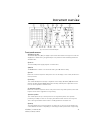
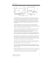
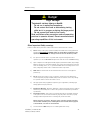
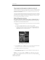
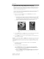
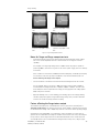
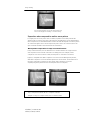
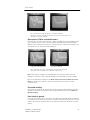
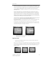
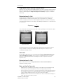
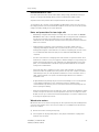
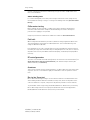
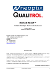
Surge Testing It is critical to perform a winding resistance test with a milli-ohmmeter or micro-ohmmeter whenever evaluating the condition of a motor winding. The surge test may not detect an open among parallel windings. Rotor loading (coupling) when testing assembled motors When testing assembled motors, the rotor can influence the shape of the surge wave pattern. These influences are as follows: 1) Loss of wave pattern amplitude: The inductive loading of the rotor causes rapid damping (little to no cycles of the ringing pattern) of the wave pattern. 2) Separated wave pattern comparison for good windings: Unbalance in the inductive coupling between the rotor and stator winding causes the wave pattern of two good phases to appear separated when they are compared. By turning the rotor, this coupling affect can be balanced out so the wave patterns superimpose. Rotor loading can be understood when the rotor is considered as a secondary of a transformer. When one phase being surged has a different number of rotor bars adjacent to its stator windings than the other phase being surged and compared, there is a different transformer action for each phase. The wave patterns on the display indicate this difference patterns when they are compared. Not all motors exhibit this characteristic. It is most prevalent in smaller, high efficiency motors with small air gaps. Separation of wave patterns that are due to rotor coupling can be determined when the wave patterns separate from the first positive peak downward, cross one another at the bottom (first most negative point) and separate again as they go upward (positive). Fig 5-22 Wave pattern comparisons for motor with rotor in place. The recommended procedure for testing assembled motors when rotor coupling may occur is as follows. Refer to Three Phase Motor Surge Test and Set-Up for detailed instructions for surge testing. If the rotor cannot be turned, carefully observe the wave pattern as the test voltage is slowly raised. Watch for a sudden shift to the left, instability or flickering which would indicate a winding fault. Many winding insulation failures will not be visible at low voltages but become apparent at a higher voltage. Note: Rotor coupling does not impede the surge impulse from stressing the turn-to-turn or phase-to-phase insulation. It only causes the rapid damping of the wave pattern. The surge test can still detect turn-to-turn or phase-to-phase shorts. Unstable, flickering wave patterns clearly indicate a fault in assembled motors whether rotor coupling is present or not. 12/2/2009 | 71-002-V5 EN ST103A, ST106A, ST112A 52 Surge Testing Fig 5-23 Motor with rotor in place and with faulty windings. One trace shifts significantly to the left. Testing assembled motors from the switchgear The Surge and HiPot tests are valid tests when testing from the switchgear at the motor control center. Not only are the windings of the motor tested, but the insulation on the connections and feeder cables phase-to-phase and phase-to-ground are tested. Follow all the procedures for surge testing (refer to Surge Testing). Keep in mind that different types and sizes of motors will give different traces, but the principle of testing assembled motors is still the same. When interpreting the wave patterns for good or bad windings, stability and symmetry are the most important factors. Warning The motor must be de-energized before testing! Connect the test leads to only the load side of the open disconnect! Notes and tips for testing from the switchgear − The test motor should be properly tagged during the test as a safety precaution. − All of the limitations and guidelines covered for testing assembled motors apply here (see Rotor Loading (Coupling) when Testing Assembled Motors). − Any power factor capacitors, surge suppression, etc., in the circuit must be disconnected. If power factor capacitors are present, no waveform will be observed when the voltage is raised. This will also happen if the motor was not connected to the cable. Only a rise in the trace on the far left will be noted. − The surge test circuit will be loaded by the feeder cable capacitance as well as the motor. Significantly higher Output settings will be needed to reach the required test voltage. If the surge tester is too small to handle both the cable and the motor load, a trace will be observed but the proper test voltage will not be reached. A higher output surge tester model will be required or the motor may have to be tested while disconnected from the feeder cable. There is no precise science to determine what size motor, with what size and length feeder cable a particular surge tester can adequately test. In general, the closer the size of the motor is to the recommended maximum motor size for a given model surge tester, the shorter the 12/2/2009 | 71-002-V5 EN ST103A, ST106A, ST112A 53 Surge Testing cables can be and still allow testing at the required voltage. Conversely, the small the motor size, the longer the cable can be. Transformers Transformers contain similar insulation systems as motors: ground, turn-to-turn and phase insulation. However, the spectrum of winding characteristics for transformers is much broader than for motors. The Surge Test is only one of many tests that should be performed to properly test a transformer. If the transformer has thousands of turns, the surge tester may not be sensitive enough to detect a single shorted winding. It may also sense the high inductance of a transformer as an open. The following testing procedures for single phase and three phase transformers provide the basics necessary to surge test transformers. Please call Baker Instrument Company, an SKF Group Company at 800-752-8272 or 970-282-1200 for further assistance or if difficulties are encountered when testing transformers. Single phase transformers 1) Jumper (or short out) the secondary side (low side) of the transformer. 2) Select TLS 1-2. Follow the diagram below to connect test leads #1 and #2 to H1 and test lead #3 to H2 of the transformer. The black ground lead connects to the frame. Fig 5-25 Single Phase Transformer connections 3) Surge test the winding following the procedures outlined for Single Phase Motors and Two Terminal Devices. The discussion of determining a fault applies. Note: Secondary winding insulation problems are reflected into the primary winding, and will be observed on the display. 4) After completing the test, reverse the test leads (connect the hot leads to H2 and the ground (#3) lead to H1) and repeat the surge test. This is commonly referred to as shooting it in the other direction. 5) Repeat this test procedure for each tap position. Three phase transformers It is beyond the scope of this manual to cover all possible transformer connections. It is important to remember that each line high side connection point must be surge tested to the other end of its own coil, and that the secondary side of the coil being surged must be shorted out (jumpered together and to ground). 12/2/2009 | 71-002-V5 EN ST103A, ST106A, ST112A 54 Surge Testing Note: A wye-wye transformer with the star point internally tied can be surge tested without opening the tie point. 1) Use TLS position1-2. 2) Connect the black ground test lead to the frame (ground) of the transformer. 3) Follow one of the charts below for connection for wye-wye or delta-wye transformers. The transformer winding should be surge tested for all the configurations shown. 4) Test procedures follow identically as for Single Phase transformer testing (refer to Single Phase Motors and Two Terminal Devices). Determination of a fault The determination of a fault when surge testing a transformer winding follows that of the Two Terminal Device (refer to Single Phase Motors and Two Terminal Devices). Wye-Wye transformers Test Leads #1 & #2 H1 H2 H3 Delta-Wye transformers Test Lead #1 & #2 H1 H1 H2 H2 H3 H3 12/2/2009 | 71-002-V5 EN ST103A, ST106A, ST112A Test Lead #3 Jumper H0 H0 H0 X0 to X1 X0 to X2 X0 to X3 Test Lead #3 Jumper H2 H3 H1 H3 H2 H1 X0 to X2 X0 to X1 X0 to X2 X0 to X3 X0 to X3 X0 to X1 55 Surge Testing 12/2/2009 | 71-002-V5 EN ST103A, ST106A, ST112A 56 6 Additional Tests The Baker Instrument Company, an SKF Group Company Surge/HiPot Tester is capable of performing two tests in addition to DC HiPot and Surge Tests. These are the Polarization Index (PI) and Step-Voltage Tests. Danger High Voltage To prevent serious injury or death: - Do not use in explosive atmospheres. Do not contact test leads or device being testing while test is in progress or during discharge period. - Do not connect test leads to live circuits. Read and follow safety precautions and safe operating practices in operator manual. Do not exceed maximum operating capabilities of this instrument. Other Important Safety warnings Failure to follow these precautions could result in severe electrical shock or death. 21) Never attempt a two-party operation. Always know what test is being performed and when. FOR EXAMPLE: DO NOT adjust test leads when footswitch is being operated. Leads will have live voltage and severe electric shock may result. 22) For capacitor-started motors or systems with surge arrestors/power factor capacitors, be sure to disconnect all capacitors from the test circuit before testing. 23) Upon completion of a DC High Potential, Megohm, Polarization Index, Step Voltage, Dielectric absorption, or Continuous Ramp test, before disconnecting the test leads, short the winding, motor, etc., to ground and allow time for discharge. If this is not done, voltage may still be active on leads and tested components. 24) Make sure the tester leads are disconnected before the motor is energized or powered up. 25) Do not remove the product covers or panels or operate the tester without the covers and panels properly installed. Components on inside of tester carry voltage for operation and if touched can render a shock. 26) Use appropriate safety equipment required by your organization, including high voltage globes and eye protection. 12/2/2009 | 71-002-V5 EN ST103A, ST106A, ST112A 57 Additional Tests 27) Repair Parts Warning : Defective, damaged, or broken test leads must be replaced with factory-authorized parts to ensure safe operation and maintain performance specifications. 28) Ground the product : This product is grounded through the grounding conductor of the power cord. To avoid electrical shock, plug the power cord into a properly wired/grounded receptacle before connecting the product test leads. Danger from loss of ground – Upon loss of the protective ground connection, all accessible conductive parts, including knobs and controls that may appear to be insulated, can cause an electric shock! 29) This instrument is NOT waterproof or sealed against water entry. 30) The unit is for indoor use. If used outdoors, the unit must be protected from rain, snow and other contaminants. Polarization Index test (PI) The Polarization Index (PI) test is useful for testing apparatus with complex insulation such as large motors and generators, where repeatable insulation resistance readings are difficult to obtain. This test measures the ratio between insulation resistance tests taken at one minute and ten minutes. Once you have valid resistance readings at each of these time increments, use the following formula to determine the polarization index: R at 10 Minutes = Polarization Index (PI) R at 1 Minute There are a number of advantages in using the Polarization Index test over a possibly everchanging insulation resistance test. − Temperature compensation is NOT necessary because you are comparing two resistance readings at the same temperature to determine the ratio. (See Resistance Temperature Compensation) − The PI test can determine insulation faults in larger test pieces with much more insulation than smaller test pieces. − Determination of the polarization index only requires two measurements. Polarization Index test evaluation − Follow IEEE Standard 43 to evaluate Polarization Index Test results. Step-Voltage test Another test that can be performed is the Step-Voltage test. This test, if used properly, can indicate the condition of winding insulation. The best results can be gained if you maintain historical records of multiple Step-Voltage tests, beginning with measurements made when the winding is new. Use the same voltage increments and time intervals for all subsequent Step-Voltage tests. Baker Instrument Company, an SKF Group Company recommends that you plot out your results on graph paper in order for you to make quick comparisons of different tests. It is important for the insulation to be free of moisture and dirt when this test is performed. 12/2/2009 | 71-002-V5 EN ST103A, ST106A, ST112A 58 Additional Tests 1) Determine the number of steps you wish to perform, at what voltages and time increments that suit your needs. For example, if your maximum voltage is12,000 volts, you may wish to use six steps of 2000 volts each. The time interval that you use will depend upon the capacitance of the test piece and the type of insulation it uses. Choose an interval that allows for a noticeable change in resistance readings at each step. Oneminute step intervals are fairly standard for many windings. 2) Take note of the resistance reading for each step. For example, with a 12kV test voltage, using steps of 2000 volts and one minute intervals, note the stabilized resistance readings at 2000 volts at one minute, 4000 volts at two minutes, 6000 volts at three minutes, 8000 volts at four minutes, 10,000 volts at five minutes and 12,000 volts at six minutes. Raise the output voltages on the tester in single motions to get the most accurate rise from one test voltage to the next. When plotted on graph paper, the results should resemble a set of ascending steps. Each step should be flat, indicating a steady resistance value. 12/2/2009 | 71-002-V5 EN ST103A, ST106A, ST112A 59 Additional Tests 12/2/2009 | 71-002-V5 EN ST103A, ST106A, ST112A 60 Typical Winding Faults Appendix A Typical Winding Faults For initial determination of winding faults, refer to the following figures. These wave patterns are typically seen for three phase, wye-connected, lap-wound induction stators. They provide a reference for associating a characteristic wave pattern with a fault-type. Note: Variation from these wave patterns is to be expected. Do not consider these wave patterns as absolute. Remember, that due to the variety of motor windings and connections that exist, each motor winding will have its own signature wave pattern. Memorization of exact matches to the following wave patterns is NOT necessary when testing. Fig A-1 Good Coil Fig A-2 Shorted Single Winding Fig A-3 Partial ground 12/2/2009 | 71-002-V5 EN ST103A, ST106A, ST112A 61 Typical Winding Faults Fig A-5: Turn-to-Turn Short Fig A-4: Ground coil Fig A-6: Coil-to-Coil Short Fig A-7: Phase-to-Phase Short Note: If all wave pattern comparisons during surge testing show considerable separation when testing three phase windings, the motor has a phase-to-phase short. Because two phases are faulty, a good wave pattern will not be achieved in any position of the TLS switch. Fig A-8: Group-to-Group short or reversed coil 12/2/2009 | 71-002-V5 EN ST103A, ST106A, ST112A 62 Appendix B Troubleshooting Please review this section before you call Baker Instrument Company, an SKF Group Company or return the unit. Self help and diagnostics Problems in testing often crop up. If you are experiencing a problem and believe the problem might be with the Baker Instrument Company, an SKF Group Company Surge/DC HiPot Tester, please take the following steps before calling or returning the unit. By performing these procedures and having the requested information available, Baker Instrument Company, an SKF Group Company’s Service or Applications Departments will be able to better analyze your situation and provide the appropriate response. Either department may be reached toll-free at 800-752-8272 or 970-282-1200 for assistance. Step #1: Basic information Take down all basic instrument information, including the following: Model # Serial # Product # example: ST112A example: A951 example: 99-115-0894 Note: All information above is located on the rear panel product label. If the tester has special options installed that you are aware of, please note these. Any and all information you know or can derive would be of help! A great tool would be a printout or sketch of the waveforms displayed on the tester. Step #2: Applications or service problem? Generally, if a problem is noted Only when testing a specific motor/generator or other coil type, then Applications would be involved. See Applications: What to do First! Please call Baker Instrument Company, an SKF Group Company, Sales Department for Applications assistance. If you can Not say the problem is associated with any One type of motor/generator, or other coil type, then Service would be involved. See Service: What to do first! Applications: What to do first! Review the section below on Common Application Problems. Please have Basic Information about your tester and specific information about the motor you are testing available when calling or faxing to assist Baker Instrument Company, an SKF Group Company personnel in determining a solution to your problem. Examples: Hp rating kW rating RPM rating Operating voltage & current How the item being tested is wound and/or number and type of coils Application of motor/generator 12/2/2009 | 71-002-V5 EN ST103A, ST106A, ST112A 63 Troubleshooting In short, any and all information you know or can derive from the motor name plate would be of help. A great tool is a printout or sketch of the waveforms displayed on the tester. If you have a FAX available, send a draft to 970-282-1010, attn: Applications. Common application problems There are a few common application-related problems which many users encounter. Please review the following cases. − The surge tester will not give the desired output test voltage for the apparatus being tested. This may happen when the test motor is too large for the surge tester, or if the impedance of the windings is too low. Refer to Chapter 5 Surge Testing for specific test procedures and results. There may also be a problem with the tester in this case. DO NOT continue testing until you have contacted Baker Instrument Company, an SKF Group Company Applications Department. − Separation of compared wave patterns is seen when surge testing on coils that are assumed to be good, even on brand new motors or windings. Often separation is seen in all three possible comparisons but to varying degrees. There may not be separation throughout the whole wave pattern. This situation can be seen in DC field or rotating poles. Be sure the coils being compared are being tested in identical configurations; i.e. both coils are wound clockwise beginning to end. On very large equipment, slight differences in capacitance may be the cause. At low voltage levels, begin the test again with the black ground lead removed from the motor frame. If the separation is now gone, capacitance was affecting the test. If the above situation does not apply there is probably an unbalance of the impedance windings that is inherent to the design. The most common case is found in basket or concentric wound motors. The phases are not magnetically balanced due to different coil lengths. To verify that the tester is working properly, perform the following test. Parallel the test leads by connecting both of the hot, red leads, indicated by the selected TLS position, from the tester to one end of a coil and the remaining red grounded lead to the other end of the coil. In this configuration, both hot leads are looking at the same coil. Therefore, there should not be any separation of the wave patterns on the display. If separation of the wave patterns is not seen (traces superimpose), the tester is operating properly and there is probably a faulted winding or a factor in the winding design that is causing the separation. If there is still separation in the wave patterns after paralleling the test leads, there is a problem with the tester and it will need to be serviced. − There is no damped sinusoidal wave pattern on the display when testing a coil. The wave pattern rises on the left and then slowly drops as it trails off to the right. It may or may not cross the zero/base line. The pattern looks like that in the figure on the next page. The test coil probably has too high an impedance to get a good working pattern. The coil may be very high in resistance and turns count. The inability to surge test this coil, or group of coils in series, will remain unless they can be broken down to smaller units of lower impedance. 12/2/2009 | 71-002-V5 EN ST103A, ST106A, ST112A 64 Troubleshooting You may also have a broken test lead or lead to the test winding. With heavy use, test leads should be checked weekly to ensure there is no breakage. Test leads are easily checked for breakage by firmly grasping the boot and clip in one hand while pulling on the lead with the other. A broken lead will stretch. A good lead will not. Service: What to do first! STOP! Do not aggravate any possible problem by INCREASING OUTPUT TO MAXIMUM looking for a screen display! NOTICES NEVER raise the output control to attain a display from a blank screen! NEVER attempt simulated problems by disconnecting the leads and positioning them to ARC against each other. NEVER come in contact with the item being tested and the test leads or with the tester and the item being tested! NEVER attempt a two-party operation. Always know what test is being performed and WHEN! NEVER attempt a BURN OUT of a detected fault with the tester! Because history has shown that several simple solutions which do not require return of a unit may arise, please perform the following checks. Open Condition Display Note the figures below. Is the display you are seeing like any of these? If yes, the unit may have at least one broken test lead causing an Open condition. In most cases, the test lead in common with the two TLS positions that produces these types of wave patterns is the lead which is broken. Verify this by pulling on the book/clip assembly of the lead. A broken test lead will stretch. If it does not repeat this procedure at one foot intervals for the length of the lead. If the leads of the tester are good, check the connections and continuity of the test winding. Display check of dual pattern There is concern about the wave pattern display. There is always one trace, never two to indicate a fault. Perform the following check. During a surge test of a coil or three phase motor, stop the test and simply disconnect one hot lead from the winding (a hot lead is one of the numbers of the selected TLS position). The display should look like one of the figures above, showing an open condition. If not, call Baker Instrument Company, an SKF Group Company Service Department for assistance. Note: Perform this test at a very low voltage. Use extra caution during the check. The disconnected test lead is still energized! 12/2/2009 | 71-002-V5 EN ST103A, ST106A, ST112A 65 Troubleshooting HiPot display checks The HiPot display shows only the VOLTAGE or CURRENT bar. One of three problems might exist. − The item being tested is in fact faulty and has either low insulation resistance or open connections. − The tester has an internal problem. − The tester has a test lead problem as shown above for an Open Condition. Disconnect the test leads from the motor and isolate the tester from any grounded surface. Reduce the Output to minimum and attempt a HiPot test with an open lead condition. Your display should indicate a rising voltage bar. The current bar may rise slightly but fall back to zero when the output increase is stopped. Do not exceed 10% rotation of the Output control! There is no need to perform this test at high voltage. If the display still shows NO voltage bar call Baker Instrument Company, an SKF Group Company Service Department. Use a meter to confirm the insulation resistance of the device being tested. Current bar operation can be tested by shorting test lead #1 and the ground lead together. Under this condition, the voltage bar will NOT move off the zero line and the current bar should rise very rapidly and activate the HiPot Overcurrent Trip warning light (HiPot Trip). If the HiPot Trip light does not light, check for open test leads at either test lead #1 or the ground lead (see Open Condition Display). If the problem persists, contact Baker Instrument Company, an SKF Group Company Service Department. HiPot trip check The HiPot trip lamp either does not activate (under known shorted conditions) or it will not go out when test is discontinued. Call the Service Department immediately for assistance. Please record information off the unit and the specific problem prior to calling. Open ground check The Open Gnd Lamp is on and you are not able to test. Answer these questions: 1) Have you recently moved the unit to a new location with possibly an ungrounded outlet? 2) Is the unit being operated in a field where the AC power source is unknown? 3) Is the unit being operated on a scope cart that has its own outlet or power source? 4) Is the unit being operated using a two-wire extension cord? 5) Are you testing from a generator? 6) Is the unit being operated on a transformer isolated circuit? 12/2/2009 | 71-002-V5 EN ST103A, ST106A, ST112A 66 Troubleshooting If you answer is yes to any of these questions, the unit is probably operational and indicating you have an open AC line ground connection. In the case of numbers 1 through 3 above, use an outlet tester to assure proper wiring connections to the outlet. For number 4, replace the two-wire extension cord with a twowire/with ground extension cord. For number 5, or any of the conditions noted above, use a grounding strap to a good earth ground. In the case of number 6, call Baker Instrument Company, an SKF Group Company Service for assistance. There is an override available but precautions should be taken. Limited output Surge waveform The display shows a limited output (amplitude) surge waveform. The display rises normally but stops at some point. Alternatively, you must continually increase the output control for successive tests to achieve the same output test amplitude. Call the Service Department immediately for assistance on this or any other abnormal condition noted. Please record basic information from the tester and the specific problem prior to calling. Warranty return Please review the Warranty Notes and Shipment sections at the beginning of this manual before sending your tester to Baker Instrument Company, an SKF Group Company for Warranty repair. The Warranty Return Form on the following page MUST BE FILLED OUT and RETURNED with the tester to obtain warranty service. This form will help to ensure that Baker Instrument Company, an SKF Group Company will identify the problem, quickly repair our unit, and return it to you. 12/2/2009 | 71-002-V5 EN ST103A, ST106A, ST112A 67 Troubleshooting Warranty return form Please fill out all the following information and return this form with your tester. Make a copy for your records before sending this to Baker Instrument Company, an SKF Group Company. Note: Be sure to follow the guidelines for shipping when sending your tester to Baker Instrument Company, an SKF Group Company. Company Name: _________________________________________________ Your Name: _____________________________________________________ Mailing Address: _________________________________________________ Shipping Address: ________________________________________________ Phone Number: _______________ Fax: ____________________ From the Name Plate on the back of the Tester: Baker Product Number: ___________________________________________ Model Number: _________________________________________________ Serial Number: _________________________________________________ Description of the Problem: Please give as much information as possible (what is not working, when it happened, what was being tested, any unusual noises, etc.) even if you already talked to someone at Baker Instrument Company, an SKF Group Company by phone. Use the back of this form if necessary. Person Contacted at Baker: ____________________________________ Ship the Tester to: Baker Instrument Company, an SKF Group Company, 4812 McMurry Avenue, Fort Collins, CO 80525, Attn: Service Manager 12/2/2009 | 71-002-V5 EN ST103A, ST106A, ST112A 68 Appendix C Model AT101 bar-to-bar armature test accessory Bar-to-bar armature test accessory The Model AT101 Bar-to-Bar Armature Testing Accessory is an adaptor which converts any Baker Instrument Company, an SKF Group Company surge tester with an output of up to 15 kV into a low impedance, high current, bar-to-bar armature tester. The bar-to-bar test method is recognized as superior to the span test method for testing armatures. To illustrate the difference between the bar-to-bar and span tests, consider this example. A manufacturer of lap wound elevator motor armatures determines that, to thoroughly test the turn-to-turn and coil-to-coil insulation, a test voltage of 400 volts across each coil is required. However, the impedance of a single coil in the armature is so low that it appears as a dead short to a conventional surge tester designed for testing AC stators. Even with the current of a 12 kV surge tester, only a few hundred volts may be generated into such a load. Most of this voltage is actually lost in the test leads of the surge tester. Consequently, the span test was developed (see the figures below). In the span test, the test contacts are placed several bars apart, so that the impedance of several coils in series is large enough to be tested with the surge tester. For example, to generate 400 volts across each coil of a 10 bar span, the test voltage must be increased to 4000 volts. However, 4000 volts at the high voltage contacts delivering the surge test will over-stress the ground insulation at the first coil in series. Therefore, the maximum test voltage must be decreased to the same level as the safe DC HiPot voltage for that motor, or about 2000 volts. Now the coils are not adequately being tested, since the bar-to-bar is only 200 volts. In a bar-to-bar surge test, 400 volts is applied directly to each coil without over-stressing the ground insulation (see figure below). The AT101 Bar-to-Bar Testing Accessory provides a specially designed low output impedance surge tester with low impedance test leads to make this test possible. Span Test 12/2/2009 | 71-002-V5 EN ST103A, ST106A, ST112A Bar-to-Bar Test 69 AT101 Bar-to-Bar Armature Test Accessory The AT101, when connected between a surge tester and an armature, converts the surge tester output from high voltage to lower voltage with high current. This is necessary for barto-bar armature testing of low impedance coil windings. The AT101 contains a high energy pulse transformer which steps down the surge tester voltage by a factor of 10 and increases the current by a factor of 10. The basic procedure involves connecting the surge tester output leads to the input of the AT101. The output of the AT101 travels through a low impedance cable assembly and armature contactor. The bar-to-bar output voltage is monitored by a peak-hold voltmeter in the AT101. The surge test wave pattern and test voltage are displayed concurrently on the surge tester CRT screen. Test voltage is measured directly at the contactor, so there is no measurement error from test lead losses. When a faulty coil is detected, the output voltage on the peak voltmeter will drop dramatically. A corresponding collapse in the amplitude and left shift of the surge test wave pattern will be evident. This is easily simulated by shorting the two bars under test with a screwdriver. In fact, the AT101 will detect shorted bars that are four or five bars away from the bars under test. Operation Note: The AT101 will show on its rear panel that it has been set up and calibrated for the specific tester you are using. It may say that it has been calibrated for an A Series Tester. 1) Ensure the AT101 line voltage selector is positioned for the line voltage to be used. 115 VAC must be showing through the window for 110 to 120 volts operation, and 230 VAC must show for 220 to 240 Volt operation. 2) Plug in the AT101. There is no power switch. The voltmeter will show 000. (The AT101 draws only 5 watts of power for the peak voltmeter, which is about the same power as an electric clock. The AT101 may be plugged in at all times, even when not testing. Note: If only one electric outlet is available, the surge tester may be plugged into the Line Out accessory plug provided on the AT101 front panel. 3) Make the appropriate connections between the AT101 surge tester. − The interconnect cable between the AT101 surge tester has a BNC connector at one end and an AMP connector at the other. Connect the BNC connector to the front panel of the AT101. The AMP plug connects to the port on the surge tester marked Auxiliary. − Connect the surge tester leads #1 and #2 to the recessed bar on the rear of the AT101. Connect surge tester leads #3 to the un-insulated ground terminal on the rear of the AT101. − The black surge tester ground lead must be connected to the armature shaft. If testing single low impedance coils using ATP02 alligator clips, connect the surge tester ground lead to the core material. Note: When using alligator clips or test probes on armatures that have bars that are wired in series, it is very important to ground at least two bars of the armature a few bars away from those that are being surged. If this in not done, very high potential voltages to ground can develop in the armature due to a transformer effect in the coils. 4) Set the surge tester Test Lead Select (TLS) switch to position 1-2. 12/2/2009 | 71-002-V5 EN ST103A, ST106A, ST112A 70 AT101 Bar-to-Bar Armature Test Accessory 5) Turn the Function knob of the surge tester to Aux. Note: The Volts/Div setting need to be divided by 10 for the bar-to-bar test when the tester is in the Aux function position. For example, 500 volts/division becomes 50 volts/division on the surge tester display. 6) Turn the surge tester Output Control to minimum. 7) Connect the armature test fixture to be used (the hand-held contactor, test probes, or test alligator clips) to the blue braided harness. (Instructions that follow will be for the hand held contactor.) The black cover may be removed to access the brushes and shape them as necessary for best contact. 8) Place the AT101 contactor on the armature commutator, making sure the contact brushes are on adjacent bars, not the same bar. 9) Press the surge tester Test (or depress the Footswitch) and raise the Output control slowly. A wave pattern should be visible on the surge tester screen and a voltage should be indicated on the AT101. Adjust the Output control until the desired bar-to-bar voltage is reached. Note: The Zero Start Interlock (ZSI) is disabled to conveniently perform this test. Positioning the Function switch to Aux automatically disables the ZSI. The true test peak voltage is correctly measured from the surge tester display as the contactor head is moved around the commutator. Be sure to divide the voltage reading by 10 during these tests. Determination of a fault As the contactor approaches a shorted pair of bars, the waveform becomes increasingly distorted, shifting left and with lower amplitude. The test brushes are over the faulty, shorted bars when the waveform amplitude is lowest. Faulty bars are read through the equalizer but the amplitude of the waveform will not be as low as when the test brushes are directly contacting the shorted bars. Fig. E-1: Determination of a Fault Note: A slight, regular rhythmic shift may be observed when moving the bar-to-bar fixture around the commutator. This is generally due to the equalizer windings and can be ignored. Hard shorted turns or insulation breakdown will be evident by an obvious change in the surge test wave pattern. When testing coils with ATP02 alligator clips, a fault should be interpreted in one of two ways: 1) A single coil should be tested by observing the wave pattern from zero volts up to the desired test voltage level. A coil with good insulation will show the same wave pattern at 12/2/2009 | 71-002-V5 EN ST103A, ST106A, ST112A 71 AT101 Bar-to-Bar Armature Test Accessory increasing voltage levels. A fault will show by the drop in amplitude and a shift to the left of the wave pattern. 2) A group of single coils may be tested by examining and recording a known good coil first. − Using the good coil, adjust the display controls to obtain the desired wave pattern on the display to be used as the reference wave pattern. − Leave all surge tester controls unchanged or record these reference settings. Begin testing on the other coils. The other coils surge test wave patterns should fit very closely to that of the first coil if they are in good condition. A shorted coils pattern will be collapsed and shifted left of the pattern of the reference coil. A piece of solder can be used to short two bars. This will simulate a fault for demonstration purposes. Application recommendations − Most armatures requiring the use of an AT101 will be tested to at least 350 volts bar-to-bar. − It is recommended that Baker Instrument Company, an SKF Group Company 6 kV model surge tester be used with the AT101 only for special applications which do not exceed 300 volts. This is quite common for lift truck armatures. − Armatures which require bar-to-bar test voltages up to 600 volts should use Baker Instrument Company, an SKF Group Company 12 kV model surge testers with the AT101. − Very large armatures, such as diesel locomotive traction motor armatures, require testing up to 750 volts bar-to-bar. These necessitate at least a 15 kV Baker Instrument Company, an SKF Group Company surge tester used in conjunction with the AT101. Alternatively, a Multiple Tester from Baker Instrument Company, an SKF Group Company may be required. Please contact us for information regarding stand alone high power armature surge and HiPot testers for large AC and DC motor work, especially heavy rail traction motors. − A 24 kV test may be used with the AT101. Its output should be limited so that the peak voltage measurement on the AT101 never exceeds 950 volts. AT101 specifications Surge Input – Maximum Voltage: 15,000 volts peak Testable Induction Range: 0.4 to 20 micro-henries (μh) Cable and Test Head Inductance: 1.0 micro-henries (μh) Transformer Turns Ratio: 10:1 Observed Voltage Step-Down: 10:1 for 5 microhenries (μh) or greater test load 20:1 for 1 microhenries (μh) load Display: Fast Acquisition peak hold voltmeter 3-1/2 Digit Liquid Crystal ½” height Maximum reading of 1999 volts Line Input: 90-135 VAC or 180-270 VAC 50/60 hertz 5 VAC maximum 500 ma fuse 12/2/2009 | 71-002-V5 EN ST103A, ST106A, ST112A 72 Appendix D Technical Specifications Technical specifications This information conforms to the requirements of MIL-M-7298D. Surge Test Output Voltage Max Output Current Pulse Energy Sweep Range Volts/Division DC HiPot Phys. Char. Repetition Rate Voltage Measurement & Accuracy Output Voltage Max Output Current Current Resolution Over-Current Trip Settings Voltage & Current Measurement & Accuracy Weight Dimensions (WxHxD) Pwr. Required ST103/06/12 A ST203/06/12 A 12/2/2009 | 71-002-V5 EN ST103A, ST106A, ST112A ST103/203A ST106/206A ST112/212A 0-3000 Volts 0-6000 Volts 0-12000 Volts 200 amps 380 amps 800 amps 0.18 joules 10-100 μ seconds 250/500/1000 /2500 60 Hz (ST103) 50 Hz (ST203) 0.72 joules 10-100 μ seconds 250/500/1000 / 2500 60 Hz (ST106) 50 Hz (ST206) 2.88 joules 10-100 μ seconds 250/500/1000/ 2500 60 Hz (ST112) 50 Hz (ST212) +/- 10% +/- 10% +/- 10% 0-3000 Volts 0-6000 Volts 0-12000 Volts 1000 μ amps 1000 μ amps 1000 μ amps 1/10/100 μ amps division 10/100/1000 μ amps 1/10/100 μ amps division 10/100/1000 μ amps 1/10/100 μ amps division 10/100/1000 μ amps +/- 5% +/- 5% +/- 5% 50 lbs./22.2 Kg 50 lbs./22.2 Kg 58 lbs./25.0 Kg 21” x 9” x 19” 560 x 210 x 480 mm Same Same 120V/60Hz/ 118W 230V/50Hz/ 118W 120V/60Hz/ 118W 230V/50Hz/ 118W 120V/60Hz/ 350W 230V/50Hz/ 350W 73 Technical Specifications 12/2/2009 | 71-002-V5 EN ST103A, ST106A, ST112A 74 Index A Auxiliary port · 14 O Open circuit · 37, 40 Operation · 8, 70 Output Voltage · 9, 73 C Cathode ray tube · 11 D Delta-connected · 39, 40, 41, 42 dielectric · 10, 19, 27 E P precautions · 46, 67 Pulse Energy · 73 R Recommended voltages · 16 Repetition Rate · 73 Resistance temperature compensation · 25 Environmental · 10 S F Footswitch · 14, 32, 33, 48, 49, 50, 51, 71 Function selector · 12 G Ground · 8, 12, 13, 14, 22, 24, 31, 33, 37, 49 H HiPot · 1, 11, 12, 13, 14, 15, 16, 19, 20, 22, 24, 25, 41, 50, 53, 57, 63, 66, 69, 72, 73 Horizontal position · 11 I Surge · 1, 12, 15, 16, 20, 27, 28, 29, 30, 31, 32, 33, 34, 35, 36, 37, 42, 44, 45, 47, 48, 49, 52, 53, 54, 57, 63, 64, 67, 72, 73 Sweep · 11, 32, 33, 51, 73 Sweep Range · 73 Synchronous · 17, 47, 48 T Test lead connections · 14 Test leads · 14, 40, 43, 65 V Vertical position · 11 Volts/div · 12 Volts/Division · 73 Intensity · 11, 16 W Wye-connected · 38, 39, 40, 42 12/2/2009 | 71-002-V5 EN ST103A, ST106A, ST112A 75 Index 12/2/2009 | 71-002-V5 EN ST103A, ST106A, ST112A 76