1
USOO8447366B2
(12) United States Patent
(10) Patent No.:
Ungari et al.
(54)
(45) Date of Patent:
CHARGING STATION FOR MOBILE
DEVICES THAT ALLOWS ACCESS TO
DEVICE SERVICES
Miller, Paul, “Sony Ericsson and Fossil team up for Bluetooth
watch,” Engadget, Sep. 28, 2006, pp. 1-16, Weblogs, Inc. http://www.
(73) Assignee: T-Mobile USA, Inc., Bellevue, WA (US)
Notice:
Subject to any disclaimer, the term of this
patent is extended or adjusted under 35
U.S.C. 154(b) by 880 days.
engadget.corn/2006/09/28/s0ny-ericsson-and-fossil-team-up-for
bluetooth-watch/ [Internet accessed: Jul. 22, 2009].
Quilty-Harper, Conrad, “Sony Ericsson’s MBW-lOO Bluetooth
watch reviewed,” Engadget, Oct. 28, 2006, pp. 1-10, Weblogs, Inc.
http://www.engadget.com/2006/10/28/s0ny-ericss0ns-mbw-100
bluetooth-watch-reviewed/ [Internet accessed: Jul. 20, 2009].
“Bluetooth Headset User Manual: Jabra BT800,” 2004, pp. 1-41,
Jabra Corporation, United States of America.
International Search Report and Written Opinion for PCT/US2009/
045531; Applicant: T-Mobile USA, Inc.; Date of Mailing: Jul. 14,
(21) Appl.No.: 12/130,627
2009, 12 pages.
(22) Filed:
* cited by examiner
May 30, 2008
(65)
Primary Examiner * Temica M Beamer
Prior Publication Data
US 2009/0298553 A1
Assistant Examiner * Joel Ajayi
Dec. 3, 2009
(57)
Int. Cl.
H04B 1/38
(52) US. Cl.
(51)
ABSTRACT
A charging station for mobile devices that allows a user to
(2006.01)
access mobile device services while a mobile device is con
USPC .......... .. 455/74.1, 552.1, 554.2, 556.1, 556.2,
tacting a charging pad or is otherwise being charged at the
charging station. The charging station includes a charging pad
where a mobile device is placed to initiate automatic charging
455/557, 566, 573, 158.4
See application ?le for complete search history.
without having to connect the mobile device to a charging
cable. The charging station also includes a display and com
USPC
(58)
May 21, 2013
OTHER PUBLICATIONS
(75) Inventors: Joseph Ungari, Seattle, WA (US);
Winston Wang, Bellevue, WA (US);
Robert Buck, Bellevue, WA (US)
(*)
US 8,447,366 B2
........................................................ ..
455/573
Field of Classi?cation Search
munication components for wirelessly linking the charging
(56)
References Cited
station with the mobile device. When the mobile device is
within proximity of the charging station, the charging station
U.S. PATENT DOCUMENTS
6,201,957 B1*
6,825,669 B2
2002/0119800 A1*
2004/0210933 A1*
3/2001
11/2004 Raichle et al.
8/2002 Jaggers et al.
10/2004
3/2006 Suzuki
2007/0036154 A1
2/2007 Lipman
2007/0279002 A1
5/2007
.. 455/550
Dresti et al. .................. .. 725/40
2006/0052141 A1
2007/0114967 A1*
establishes a connection with the mobile device to allow the
Son et al. .................... .. 455/406
services offered by the mobile device to be accessed via the
charging station. The display on the charging station may be
larger than the display of the mobile device or may be con
?gured with different dimensions than the display on the
mobile device.
Peng ........................... .. 320/101
12/2007 Partovi
29 Claims, 8 Drawing Sheets
US. Patent
May 21, 2013
Sheet 1 0f8
US 8,447,366 B2
US. Patent
May 21, 2013
Sheet 2 0f8
US 8,447,366 B2
US. Patent
May 21, 2013
US 8,447,366 B2
Sheet 3 0f 8
mom
cosmEz?h
0mmown
{02:
wc:o=mEz o “$63920!
own
S
m
5
o
mwm
{0sz5H
ownmen
0mmmom
369021
263502a
2052 /
cor
mow
@=05:9m2e0
£065
0mmm5
@29B0mz m
Ewmxbaouw
o>m9t3E.5
Emowm
w20a:u6o.i5
momoow
mwmwww
9$hwx8m0a6w
$2@8536192/50
motwg
US. Patent
May 21, 2013
Sheet 4 0f8
US 8,447,366 B2
Detect mobile device?
460
Transmit inquiry to mobile
device
Response to
inquiry received?
No
475
Has
detected
mobile device been
Request pairing
information
previously
480
airing information
received?
aired?
Yes
490
Retrieve stored pairing
Store pairing information
information
i
495
Establish trusted relationship A
with mobile device
i
498
Access mobile device services
End
FIG. 4
US. Patent
May 21, 2013
oom
Sheet 5 0f 8
$2
R22,
owm.A
O
O”
wmpoc 65%m
32 6 x0 9 O 250E Eco
OED 2 :8 62:8
G 9:.832 O
US 8,447,366 B2
US. Patent
May 21, 2013
US 8,447,366 B2
Sheet 6 0f 8
cow
mrmk
1f
\
“M$2u5m,2 y
#5sz
o92m6>w:n@QEnNP
5a. 0?o%sm
05v
w2
UR2==8CO>m
wE8m1:S?2A
wmmg
J
\
“A.@F?
f\/:9%:@\8E2ow/?m>no m(O
G8a2
R22,O
L.x
.“820635:3\l
j
muENE
US. Patent
000
May 21, 2013
US 8,447,366 B2
Sheet 7 0f 8
8%
\L
R23
R22,m
14
@oEQE\
<HNF
Kf5m9bh20ao9?mi>nu5m
wM?m$n2?0mw >1rwa5-0m2l.omj\
DuENE
\/3E95:$h90ow?m>ngm
.mw>BEQEU=6Nmc?w<0 $2N§-0m8w
J
\
Qw~ka
US. Patent
May 21, 2013
US 8,447,366 B2
Sheet 8 0f 8
can
©Egg05.55
NF
2
E‘
m?
m:
t.
w_\
mmvNFNQNQF
> mow
ommmmN N
y
US 8,447,366 B2
1
2
CHARGING STATION FOR MOBILE
DEVICES THAT ALLOWS ACCESS TO
DEVICE SERVICES
includes a display and communication components for wire
lessly linking the charging station with the mobile device.
When the mobile device is within proximity of the charging
station, the charging station establishes a connection with the
mobile device to allow the services offered by the mobile
device to be accessed via the charging station. For example, if
BACKGROUND
When mobile devices, such as mobile telecommunications
the mobile device is a mobile phone, a user may make calls
devices (e.g., mobile phones, personal digital assistants
from the charging station by accessing the address book of the
mobile phone, selecting a number to call, and placing the call
(PDAs), portable email devices, Blackberrys, etc.), personal
media players, or like devices are being charged, they are
from the charging station. The charging station thereby
typically not used by a user. A user’s hesitancy to use a mobile
greatly extends the usability of a mobile device in a home,
business, or other setting.
In some embodiments, the display on the charging station
may be larger than the display of the mobile device or may be
con?gured with different dimensions than the display on the
mobile device. As a result, the charging station display may
portray multiple services, may portray a greater amount of
device during charging periods may arise for different rea
sons. In some situations, the power cord used to connect a
mobile device to a power outlet may be too short to allow a
user to comfortably use the device. In some situations, the
power outlet used to charge the device may be in a location
that isn’t conducive to use of the device. For example, the
power outlet may be located in a high traf?c area like a kitchen
information for a single service, or may format information in
a different fashion for presentation to a user. The display of
where a user may not feel comfortable holding a conversation
for a long period of time or where the general noise level may
20
the charging station thereby enhances the amount and type of
data that may be accessed by the user using the services of the
make it dif?cult to use the device. And in some situations, a
mobile device may be charged in a location where there are
more convenient options for communication or other services
mobile device.
offered by the mobile device. For example, rather than use a
mobile telecommunications device (e.g. a mobile phone), a
station may be replaced with a dock or traditional cable that
allows the mobile device to be connected to a power supply
In some embodiments, the charging pad of the charging
25
user may be more inclined to use a landline phone at his/her
for recharging. While less convenient than the charging pad,
residence because of the convenience of the landline phone.
a dock or traditional cable require no modi?cations to mobile
As another example, rather than use a PDA to access a
weather service and obtain a weather forecast, a user may be
devices in order to allow device charging.
more inclined to use a home computer or turn on a television 30
services offered by other nearby devices. For example, the
charging station may include communication components for
wirelessly linking the charging station with a computer or
In some embodiments, the charging station offers access to
to obtain a weather forecast. By limiting the use of a mobile
device during charging periods, users cannot ?llly take
advantage of the services that are provided by the mobile
other Internet appliance that is located in close proximity to
device. As a result, it would be advantageous to improve on
the charging station. A user may use the charging station to
establish a connection with the proximate device and access
the manner and circumstances in which mobile devices can be
35
the services offered by the device via the charging station.
Although the charging station may offer minimal functional
ity on its own, the charging station therefore provides an
utilized.
BRIEF DESCRIPTION OF THE DRAWINGS
interface to other proximate devices that are able to offer
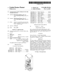
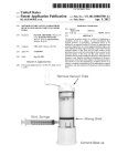
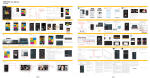
FIG. 1 is a perspective diagram of a charging station with a
40 useful services to a user.
Various embodiments of the invention will now be
mobile device positioned on the charging station for charging.
FIG. 2 is a perspective diagram of a charging station for
described. The following description provides speci?c details
mobile devices used in a consumer setting.
for a thorough understanding and an enabling description of
FIG. 3 is a block diagram of components in a charging
station and in a mobile device to enable charging of the
mobile device and the use of services offered by the mobile
device.
these embodiments. One skilled in the art will understand,
however, that the invention may be practiced without many of
45
these details. Additionally, some well-known structures or
functions may not be shown or described in detail, so as to
avoid unnecessarily obscuring the relevant description of the
various embodiments. The terminology used in the descrip
tion presented below is intended to be interpreted in its broad
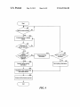
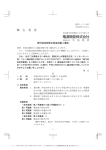
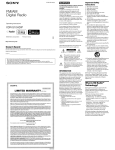
FIG. 4 is a ?ow chart of a process for detecting a mobile
device and services offered by the mobile device.
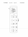
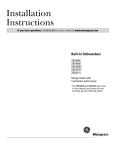
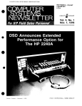
FIG. 5 is a representative user interface on the charging 50
est reasonable manner, even though it is being used in con
station to allow a user to access services offered by the mobile
device.
junction with a detailed description of certain speci?c
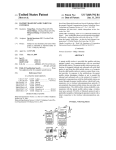
FIGS. 6A-6D are representative screenshots of a user inter
Iace which depict a user accessing an address book and com
embodiments of the invention.
FIG. 1 is a perspective diagranr of a charging station 100
that allows a mobile device 110 to be charged while at the
munication service through the mobile device.
55
same time allowing a user to access communication or other
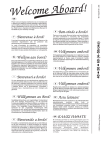
FIG. 7 is a representative user interface which depicts a
user accessing a calendar service through the mobile device.
services that are offered by the mobile device or by another
device. The mobile device 110 may be a mobile telecommu
60
nications device (e. g., a mobile phone, a personal digital
assistant (PDA), a portable email device, a Blackberry, etc.),
65
mobile device having batteries and offering services via a
wireless connection. The charging station 100 includes a
charging pad 120 upon which a mobile device is placed to
engage the charging station’s charging features. Various tech
DETAILED DESCRIPTION
A charging station for mobile devices that allows a user to
access mobile device services while a mobile device is being
charged at the charging station or is located adjacent the
charging station is disclosed. The charging station includes a
charging pad where a mobile device is placed to initiate
automatic charging without having to connect the mobile
device to a charging cord or cable. The charging station also
a personal media player such as an iPod or Zune, or any other
nologies may be used to automatically implement cordless
charging. In some embodiments, the charging pad 120 is
US 8,447,366 B2
3
4
comprised of a plurality of conductive strips through which
interface on the display. In embodiments where the display is
not a touchscreen, a keypad, buttons, knobs, or other controls
current may ?ow. A mobile device is con?gured with a plu
rality of contact points that protrude from the case of the
may be used on the charging station to allow a user to select
functions or enter text. For example, one or more keys may be
mobile device and which come into contact with two or more
deployed aron the periphery of the display 150, and the
of the plurality of conductive strips when the mobile device is
placed on the conductive pad. The connection formed
between the contact points and the conductive strips allow
current to ?ow from the charging pad to the mobile device,
which may be used to charge the batteries of the mobile
user may select a key that corresponds to text that is displayed
adjacent to that key on the display.
The display 130 on the charging station is typically larger
under the WildChargeTM brand. In some embodiments, the
than the display that is contained on the mobile device 110. As
a result, the display 130 may be used to display a greater
amount of information than would normally be viewable on a
single screen of the mobile device. To take advantage of this
charging pad 120 operates using magnetic induction. A vary
ing magnetic ?eld is generated by the charging pad. A mobile
tioned into a number of regions that each has a different
device. Such contact-point-based charging pad technology is
offered by WildCharge, Inc. of Scottsdale, Ariz. and sold
capability, in some embodiments the display may be parti
device placed on the charging pad is brought within the mag
purpose. For example, the display 130 shown in FIG. 1 has
been partitioned into a ?rst region 140 that is devoted to
displaying the time and date, and a second region 150 that is
netic ?eld, and current is inductively induced in a receiver that
is built into the mobile device and used to charge the batteries
of the mobile device. Such magnetic-?eld-based charging
currently being used to depict the status of a phone call being
pad technology is offered by Splashpower Ltd. of Cambridge,
20
made by a user through the mobile device. As another
example, the ?rst region may be devoted to one mobile device
25
service (e.g., an address book) while the second region may
be devoted to another service (e.g., a chat application). It will
be appreciated that a greater or lesser number of regions may
be displayed to a user, and the purpose of each region may be
?xed or may be dynamically changed over time.
UK, and sold under the SplashpowerTM brand. It will be
appreciated that other cordless charging technologies may be
used to construct the charging pad 120.
While only a single mobile device 110 is depicted in FIG.
1 as being charged on the charging pad 120, two or more
mobile devices may be charged at the same time. The number
While the charging pad 120 is depicted as extending in
front of the display 130 in FIG. 1, it will be appreciated that
the charging pad may instead extend to the side of, behind,
of mobile devices that may be simultaneously charged
depends on the size of the charging pad, the size of each
mobile device, and the cordless charging method used by the
charging pad. Moreover, although the charging station 100
single charging pad technology, it will be appreciated that the
above (e.g., on a top surface) or beneath (e.g., in a shelf or
opening) the display. Since it is not necessary for a user to be
able to see or manipulate the mobile device 110 while the
charging station may have two or more charging pads based
device is on the charging pad, the charging pad may be placed
on the same or different charging pad technologies. The use of
in any location that minimizes any interference with the
operation of the display 130 or any associated controls on the
depicted in FIG. 1 has only a single charging pad based on a
30
multiple technologies to implement the charging pad allows
the charging station to accommodate a greater range of
mobile devices.
35
In addition to a charging pad 120, the charging station 100
includes a display 130, which in some embodiments is a
touchscreen display. The touchscreen display may be a Liq
uid Crystal Display (LCD), an Organic Light-Emitting Diode
(OLED) display, a Liquid Crystal on Silicon (LCOS) display,
40
mobile device and the use of services offered by the mobile
device through the charging station. The mobile phone 300
etc.As will be described in additional detail herein, the charg
ing station includes communication components that enable
includes a data storage medium component 305 (e.g., hard
drive, ?ash memory, memory card, etc.) that stores content
services of the mobile device or of other proximate devices to
be accessed via the display. For example, if the mobile device
charging station. The charging pad may also be placed in a
location that maximizes the aesthetic aspects of the charging
station.
FIG. 3 is a block diagram of various components in the
charging station 100 and a mobile device, in the depicted
example a mobile phone 310, that enable charging of the
45
and other data (e.g., processing instructions, con?guration
being charged is a mobile phone, a user may use the charging
settings, etc.), and a processor 310 for executing processing
pad 120 to make a telephone call by accessing the address
instructions and implementing phone services. To allow a
book of the mobile phone via the charging pad’s display 130,
user to interact with and use the communication and other
selecting a number to call, and placing the call. As another
example, a user may use the display 130 to look up an address
contained in an address book of the mobile device. As another
50
example, a user may use the display 130 to select and play
music that is stored in a media player mobile device. When a
a
a
I
,
services of the mobile phone, the mobile phone may include
a display 315, a keypad or touchpad 320, a microphone 325,
and a speaker 330. A power module 335 having a charging
interface 340 and a battery 345 provide power to the mobile
phone. As discussed above, the charging interface 340 may be
'
display allows a user to access functionality that is resident in
55
the charging station. For example, the charging station may
The mobile phone 300 includes two communications com
ponents. The mobile phone includes a Bluetooth component
include a clock component and a radio tuner. When a mobile
device is absent, the user may view the time or listen to a radio
360 or other communication component that implements a
station using the charging station. FIG. 2 depicts, for
example, a bedroom environment 200 in which the charging
60
short-range communication protocol (e.g., WiFi, Ultra-wide
band, ZigBee, infrared, etc.). The mobile phone 300 also
includes a network communication component 350 that
station is used as a clock radio.
The charging station 100 allows a user to select options or
enter text by various interfaces that are presented on the
display 150. If the display is a touchscreen, the user may
select options by touching icons or operating controls that are
point or magnetic ?eld charging.
enables the mobile phone to communicate by transmitting
and receiving wireless signals using licensed, semi-licensed
or unlicensed spectrum over a telecommunications network
65
355. Telecommunications networks include third-party tele
present on the display. To allow a user to enter text, the
communications networks such as a Global System for
charging station may present a keyboard or other text-entry
Mobile (GSM) mobile telecommunications network, a code/
US 8,447,366 B2
5
6
time division multiple access (CDMA/TDMA) mobile tele
communications network, a 3rd Generation (3G) mobile tele
communications network (e. g. General Packet Radio Service
(GPRS/EGPRS), Enhanced Data rates for GSM Evolution
(EDGE), or Universal Mobile Telecommunications System
(UMTS)), or other telecommunications network. Those
skilled in the art will appreciate that various other compo
nents (not shown) may be included in the mobile phone to
enable network communication. For example, if the mobile
allow a user to select functions and enter data. The charging
station 100 also includes a power supply 395 that is coupled
to the charging pad 120. The charging station is typically
plugged into an electrical outlet, and the power supply regu
lates the power and converts the power into a form that is
required by the charging pad. As discussed above, the charg
ing pad 120 may utilize one of a variety of cordless charging
technologies, such as contact-point or magnetic ?eld charg
ing.
The charging station 1000 includes at least one communi
phone is con?gured to communicate over a GSM mobile
telecommunications network, the mobile phone may include
cations component. For instance, the charging station 100
a Subscriber Identity Module (SIM) card that stores an Inter
may include a Bluetooth component 405 to allow the charg
ing station to communicate with a mobile device. In lieu of or
in addition to the Bluetooth component, the charging station
may include any other communication components that oper
national Mobile Subscriber Identity (IMSI) number that is
used to identify the mobile phone on the GSM mobile tele
communications network. If the mobile phone is con?gured
ate using a short-range communication protocols (e. g., Wi-Fi,
Ultra-wideband, ZigBee, infrared, etc.) that are necessary to
to communicate over another telecommunications network,
the mobile phone may include other components that enable
it to be identi?ed on the other telecommunications network.
In some embodiments, the mobile phone 300 includes com
ponents that enable it to connect to a telecommunications
communicate with a mobile device or with other proximate
devices. In some embodiments, the charging station may
20
network using Generic Access Network (GAN) or Unli
censed Mobile Access (UMA) standards and protocols. For
example, the mobile phone may include components that
support Internet Protocol (IP)-based communication over a
Wireless Local Area Network (WLAN) and components that
25
broad range of mobile devices and other proximate devices.
The components depicted in FIG. 3 create two interfaces
between the charging station 100 and the mobile phone 300.
The ?rst interface is a charging interface 375 that is estab
lished between the charging pad 120 of the charging station
and the charging interface 340 of the mobile phone. The
charging interface 375 allows the mobile phone to engage the
enable communication with the telecommunications network
over the IP-based WLAN.
With the exception of the charging interface 340 that is
unique to the type of cordless charging technology that is
being used, the components in the mobile phone 300 are
include multiple short-range communication components in
order to enable the charging station to communication with a
charging station 100 charging features, permitting the battery
30
345 of the mobile phone to be charged from power provided
phones. The mobile phone may contain application programs
by charging station. The charging is performed cordlessly and
automatically when the mobile phone is brought into close
that allow a user to access various services that are local to the
proximity or into contact with the charging pad. The second
therefore those that are typically found in most mobile
phone. For example, the mobile phone may contain an appli
cation that is stored in the phone memory and that allows a
interface is a communications interface 399 that is estab
35
lished between, for instance, the Bluetooth module 405 of the
charging station and the Bluetooth module 360 of the mobile
phone. The communications interface allows the charging
station to wirelessly exchange data and commands with the
mobile phone. The communications interface thereby allows
40
a user of the charging station to access communications and
user to play a game on the mobile phone even if the mobile
phone is not connected to a telecommunication network. The
mobile phone may also contain an operating system or appli
cations that allow a user to access various services that are not
located on the phone. For example, the mobile phone may
other services that are offered by the mobile phone.
In some embodiments, the components depicted in FIG. 3
allow a user to access an address book or pictures that are
stored on a remote server that is accessed through a telecom
munication network. Further, the mobile phone may contain
data ?les consisting of images or video that may be displayed
on the mobile phone’s display.
While the mobile phone 300 depicted in FIG. 3 contains
components that enable both short and long range communi
cations, it will be appreciated that other mobile devices 110
45
established between the charging station and one or more
proximate devices via Wi-Fi or other short-range communi
cation protocols. The communications interface allows the
charging station to wirelessly exchange data and commands
may incorporate components that implement only short range
communications. For example, a mobile media player device
may only offer short range communication capability via
50
thereby allows a user of the charging station to access com
infrared, etc.
Turning to the charging station 100, the charging station
55
settings, etc.), and a processor 370 for executing processing
60
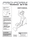
mobile device, and to pair with the mobile device in order to
utilize the services offered by the mobile device. At a decision
block 455, the charging station 100 waits to detect that a
mobile device has been placed on (i.e., has been engaged
with) the charging pad 120 for charging. In some embodi
ments, the charging station is able to detect such engagement
as a result of periodic beacon signals transmitted by the charg
vices of the mobile device, the charging station includes the
display 130, a microphone 380, and one or more speakers
385. The charging station may include various user interface
controls 390 (e.g., keypad, buttons) to allow a user to select
functions and enter data. If the display 130 is a touchscreen
display, however, the interface controls 390 may be omitted or
limited and the display used as the primary mechanism to
charging station 100 to detect a mobile device 110 (such as a
mobile phone 300), to ascertain services offered by the
and other data (e.g., processing instructions, con?guration
instructions. To allow a user to interact with the charging
station and gain access to the communication and other ser
with the proximate device. The communications interface
munications and other services that are offered by the proxi
mate device(s).
FIG. 4 is a ?ow chart of a process 450 implemented by the
protocols such as Bluetooth, WiFi, Ultra-wideband, ZigBee,
includes a data storage medium component 365 (e.g., hard
drive, ?ash memory, memory card, etc.) that stores content
also create an interface between the charging station 100 and
other proximate devices (not shown) such as a computer or
Internet appliance. A communications interface may be
ing station and/or mobile device. In some embodiments, the
65
charging station is able to detect such engagement as a result
of detection of additional weight placed on the charging pad
120. In some embodiments, the charging station is able to
US 8,447,366 B2
7
8
detect such engagement by monitoring the delivery of power
via the charging pad (e.g., when charging is detected, it is
associated with a service available on the mobile device. A
user may select a service by pressing the appropriate icon on
the touchscreen of the charging station. For example, the user
may access the voicemail of the mobile device by selecting
the “voicemail” icon. As another example, the user may
access pictures and videos stored on the mobile device by
selecting the “media” icon. While nine icons are displayed in
the representative interface 500, it will be appreciated that a
greater or lesser number of icons may be displayed by the
charging station. When the charging station detects that an
icon has been selected, the charging station issues an appro
priate command to the mobile device via the communications
interface 399. The mobile device transmits responsive service
data to the charging station if the data is stored locally on the
presumed that a mobile device is present). At a block 460, the
charging station transmits an inquiry to the mobile device in
which it requests the device name, device class, list of ser
vices and other technical information about the device. At a
decision block 465, the charging station waits to receive a
response from the mobile device. If a response is not received
within a certain time period, the charging pad will transmit
another inquiry to the mobile device at block 460. If a
response is received from the mobile device within a certain
time period, processing continues to decision block 470.
At decision block 470, the charging station determines
whether it has previously paired with the mobile device. The
determination may be made by comparing the identi?cation
mobile device, or accesses a remote service via the telecom
munications network 355 if the service involves remote data
information received in the response from the mobile device
with a table of previously-paired devices that is stored in the
data storage area 365. If the mobile device has not been
or communication with another party. By exchanging data
previously paired with the charging station, processing con
tinues to block 475 where the charging station requests pair
ing information from the user. The pairing information
enables the charging station and the mobile device to estab
lish a trusted relationship. At a decision block 480, the charg
ing station waits to receive pairing information from the
mobile device. If pairing information is received from the
mobile device (i.e., if pairing information is con?rmed by a
user), at a block 485 the pairing information is stored in the
data storage area 365 for future reference. Processing then
20
In some embodiments, the software necessary to offer a
service to a user may entirely reside on the mobile device 110
25
continues at block 495. If at decision block 470 it is deter
mined that the mobile device has been previously paired with
the charging station, processing continues to block 490 where
the charging station retrieves stored information from the data
storage area 365 that allows the charging station to pair with
the mobile device. At block 495, the charging station estab
30
lishes a trusted relationship with the mobile device. The
trusted relationship may or may not involve the encryption of
35
munication services (e.g., voice, text), calendars, address
books, notes, reminders, media (e.g., pictures, music, video)
appreciate that software functionality may be advantageously
offered via a mobile device. In some embodiments, the charg
ing station may offer a signi?cant number of local services to
40
In some embodiments, the software on the charging station
mobile device and integrate the data received from the
accessed services for simultaneous display on the charging
45
presented on the mobile device, although scaled or truncated
to ?t the display of the mobile device. Alternatively, the user
station display 130. For example, the charging station may
display a menu to allow a user to make a phone call at the same
50
time as a calendar is being displayed. On the mobile device,
the phone call and the calendar are normally accessed via
different menu screens, but because of the larger display size
on the charging station the menu and calendar may be brought
together and displayed on the same screen.
In some embodiments, the software on the charging station
acts as an intermediary between a mobile device and a proxi
mate device such as a computer or an Internet appliance. For
55
books, notes, reminders, media (e.g., pictures, music, video)
or any other services that may be implemented on a mobile
device or that are accessible through a mobile device.
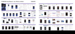
FIG. 5 is a representative user interface 500 that may be
presented on the charging station display 130 to allow a user
to access services offered by the mobile device. The user
interface may be a duplicate of the user interface that is
a user and a limited number of services may be accessed via
a mobile device.
may allow a user to access a number of services offered by the
station is allowed to access will depend on the type of mobile
device and the speci?c user or manufacturer settings of the
mobile device. Services that may be accessed include com
munication services (e.g., voice, text), calendars, address
mance. In some embodiments, the majority of the services
that a user accesses at a charging station are services that are
or any other services that may be implemented on a mobile
device or that are accessible through a mobile device.
At a block 498, the charging station is allowed to access
communication and other services offered by the mobile
device. The number and type of services that the charging
and only user interface data is transmitted to the charging
station. In some embodiments, the charging station may
include software that executes on the charging station and that
aids in offering a service to the user. For example, the charg
ing station may execute a user interface application that refor
mats, enhances, or supplements data received from the
mobile device for display on the charging station display. As
another example, the charging station may execute a data
compression algorithm to speed the transmission of data over
the wireless communications link. Those skilled in the art will
divided between the station and the device to improve perfor
data that is exchanged between the charging station and the
mobile device.
At a block 498, the charging station is allowed to access
communication and other services offered by the mobile
device. The number and type of services that the charging
station is allowed to access will depend on the type of mobile
device and the speci?c user or manufacturer settings of the
mobile device. Services that may be accessed include com
with the charging station over the communications interface
399, the mobile device enables the user to remotely access
services that are typically accessed using the mobile device.
instance, the charging station may be con?gured to signal a
proximate device whenever a mobile device is within range of
and establishes communications with the charging station or
when a mobile device commences charging via the charge
pad.
60
In some embodiments, a mobile device user is allowed to
limit the services that may be accessed from a charging sta
tion. For example, the mobile device user may desire to limit
the ability to make long distance telephone calls using a
charging station. The mobile device may therefore provide a
interface may be a reformatted or enhanced user interface that 65 settings management menu to allow a user to enable or dis
is mapped to the user interface of the mobile device. The
interface depicts a number of icons 510, each icon being
able services that are to be offered through the charging
station.
US 8,447,366 B2
10
FIGS. 6A-6D are screenshots of a representative interface
510, the user would be taken to a calendar that is maintained
on the mobile device or in a service utilized by the mobile
device. FIG. 7 is a screenshot of an interface 700 to a calendar
that is presented on the charging station display 130. The
screenshots depict a series of screens that a user might use to
access a communication service through a mobile device.
FIG. 6A depicts a ?rst screen 600 that allows a user to select
a device. If more than one mobile device has engaged the
service. A ?rst region 705 in the interface depicts the month at
a glance, so that a user can see and easily select a particular
day of the month. A second region 710 of the interface depicts
charging system of the charging station, a user may initially
a detailed schedule for three days of the month, with the
various activities associated with each day displayed on the
schedule. It will be appreciated that the display 120 of the
need to select which device the user would like access. In the
depicted example, two mobile devices are identi?ed in a
message 605 that is displayed to a user. The devices may be
charging station may be signi?cantly larger than the display
identi?ed by device type (e.g., Samsung Beat, Nokia 6103,
Motorola RAZR), by nickname (e.g., “Rick’s phone”), by
of the mobile device. As a result, a greater amount of infor
mation may be contained in charging station user interfaces
when compared to mobile device user interfaces. For
example, a mobile device may not be able to depict the ?rst
user name associated with the phone (e.g., “John Smith”), by
photo, by icon, or by any other identi?er. The user may select
which device to access by selecting a radio button 610 asso
ciated with the device. In some embodiments, the user may be
required to enter a password or otherwise verify that they are
authorized to use the device before proceeding.
Once a device is selected, the user is presented with a menu
of services that may be accessed through the selected device.
and second regions shown in FIG. 7 in the side-by-side man
ner that is shown.
From the foregoing, it will be appreciated that speci?c
20
made without deviating from the spirit and scope of the inven
FIG. 6B depicts a second screen 615 that allows the user to
select a service. The second screen identi?es which device is
being utilized in a banner 620 that appears at the top of the
screen. The second screen also depicts a number of icons 625,
each icon being associated with a service available on the
mobile device. A user may select a service by pressing the
appropriate icon on the touchscreen of the charging station. It
will be appreciated that the number of services that are dis
tion. Although wireless technologies were discussed for use
in implementing the charging pad 120, it will be appreciated
25
played will depend on the particular device that is being
accessed by the user and other factors.
If the user selects one of the services accessible though the
mobile device, the user may be presented with a menu asso
ciated with the selected service or with data associated with
selected service. FIG. 6C depicts a third screen 630 that
presents additional details of the selected service. To arrive at
the third screen depicted in FIG. 6C, the user selected the
“address book” icon from the set of displayed icons 625 in the
second screen 615. The user’s address book 635 is therefore
displayed to the user, sorted alphabetically by last name. The
user may scroll within the address bookusing a scroll bar 640.
that various wired solutions may be used in lieu of the charg
ing pad. For example, a dock, a cable, or other coupling
component may be used to provide power from the charging
station 100 to the mobile device 110 for purposes of recharg
ing the batteries of the mobile device. Accordingly, the inven
tion is not limited except as by the appended claims.
30
We claim:
1. A charging station for charging a mobile telecommuni
cations device while enabling access to services through the
mobile telecommunications device, the charging station com
35
prising:
a power supply;
a charging pad coupled to the power supply, the charging
pad con?gured to charge a mobile telecommunications
device in proximity to the charging station via a cordless
40
connection;
a communication component for establishing a wireless
communication link with the mobile telecommunica
tions device while the mobile telecommunications
When a user ?nds the name of a party that he/ she would like
to call, the user may select that name by tapping or otherwise
selecting the name. In FIG. 6C, the name “James Andrew” has
been selected by the user as indicated by the highlighting 645
that is applied to the name after selection.
embodiments of the invention have been described herein for
purposes of illustration, but that various modi?cations may be
device is being charged by the charging pad, the wireless
45
communication link enabling access to at least one ser
Once the user has selected a name from the third screen
vice offered by the mobile telecommunications device,
630, the mobile device may be con?gured to automatically
the at least one service selected from a voice service, a
text message service, a calendar service, an address
book service, or a multimedia service;
dial the user. FIG. 6D depicts a fourth screen 650 that indi
cates that a call is being made to “James Andrew.” Progress of
the call may be displayed to the user in a message 655.
50
a touchscreen display for displaying an icon that depicts at
least one service offered by the mobile telecommunica
tions device and for receiving the selection by a user of
one of the displayed services by detecting a touch of the
55
a controller coupled to the communication component and
to the input component, wherein the controller receives
Although the selection of the party to call is made on the
charging station, the connection to a wireless telecommuni
cations network to complete the call is made by the wireless
device. When the call has been initiated, the user may com
municate with the other party by speaking into the micro
phone 380 of the charging station 100 and listening to the
other party via the speaker 385 of the charging station. All
user on the icon; and
a selection of a service by the user and allows the user to
voice signals are transmitted from the charging station to the
mobile device via the Bluetooth connection, before being
communicated from the mobile device to the other party via
the telecommunication network 355. The charging station
60
access the selected service offered by the mobile tele
communications device via the wireless communication
link.
2. The charging station of claim 1, wherein the charging
pad creates a varying magnetic ?eld to induce a charging
current in the mobile telecommunications device.
thereby increases the opportunity to use mobile device ser
vices at times when services would typically go unused, such
as during charging periods.
through the charging station. If, for example, the user selected
3. The charging station of claim 1, wherein the charging
pad provides a charging current to the mobile telecommuni
cations device when conductive contact is made between the
the icon corresponding to the “calendar” in the set of icons
mobile telecommunications device and the charging pad.
Other mobile device services may, of course, be accessed
65
US 8,447,366 B2
11
12
4. The charging station of claim 1, wherein the communi
cation component communicates via a protocol selected from
a set comprising Bluetooth, WiFi, Zigbee, ultra-wideband
and infrared.
5. The charging station of claim 1, wherein the selected
service is implemented on the mobile telecommunications
device.
6. The charging station of claim 1, wherein the selected
service is implemented remote from the mobile telecommu
nications device and accessed via the mobile telecommuni-
cations device
17. The charging station of claim 16, wherein the controller
receives a selection of a second service from the user and
accesses the selected second service on the mobile device via
the wireless communication link, and wherein the display is
con?gured to simultaneously display the selected ?rst and
second services.
18. The charging station of claim 9, wherein the selected
service is accessed after the mobile device has been charged.
19. The charging station of claim 9, wherein the mobile
10
-
-
.
.
.
.
deV1ce 1s a mobile telecommunications deV1ce.
7. The charging station of claim 1 wherein the selected
20'The Chgrgifg.smi°n°f°1aim9’Whereifaponlon Ofthe
service is accessed after the mobile telecommunications
seleCted sen/Ice ls Implemented by the mOblle deVICe and a
device has been Charged
portion of the selected service is implemented by the charging
-
-
'
-
-
-
8. The charging station of claim 1, wherem a portion of the 15 S
selected service is implemented by the mobile telecommuni-
tation.
_
21' An.aPPara.ms for. the remOte. access. Of? self/Ice Offered
cations device and a portion of the selected service is imple-
by a mOblle deVICe
mented by the charging station.
the ap?arams compnsmg:
9. A charging station for charging a mobile device and
1e the mOblle deVICe ls bemg Charged’
?
d
h
b.1
a (Ci afgmg. 00111133111th con g“? to C arge a mo le
displaying a list of services available on the mobile device 20
eVICe Vla a,cor ess connectllon’
thatausermay access through the charging station, the charg-
b1, hi
. 1
a commumpanpn 0.011113011th or em} 15 1.1g a ere ess
ing station comprising:
a power supply
a Charging component coupled to the power supply the
Charging component con?gured to Charge a mgb?e 25
communication link With the mobile deV1ce while the
mobile device is being charged by the charging compo
nent, the Wireless communication link enabling access
to at least one service offered by the mobile device, the
device in proximity to the charging station via a cordless
at leaSt one SeTVlce seleCted from 2.1 VOlce serVICe’ a teXt
connection
message serV1ce, a calendar serV1ce, an address book
a communication component for establishing a wireless
Servlce’ or a mulnmedla sen/1,0 e,; and
communication 1ink With the mobile device While the
an interface component for rece1vmg from a user a selec
mobile device is being charged by the charging compo- 30
non Ofap Icon that deplqs at leaSt one sen/Ice? Offeer by
nent, the wireless communication link enabling access
to at least one service offered by the mobile device, the
the mOblle deche’ the Inlerfapé component lncmdmg a
touchscreen (115131.213, that IS utlhzed by the user to selém
at least one service selected from a voice service, a text
message service a calendar service an address book
the con that deplots the sen/Ice Offered by the mOblle
deV1ce, the interface component accessing the selected
service or a muf?media service,
’
35
service on the mobile device via the wireless communi
a touchscreen display for displaying an icon that depicts at
canon 119k afld prOVIdmg the sen/Ice to the user’ Wherem
least one service offered by the mobile device and for
the S.erVICe. ls accessed from the apparatus usmg the
receiving the selection by a user of one of the displayed
2211319113116 deVICe' f 1 . 21 h . h h .
services by detecting a touch of the user on the icon; and
' . e apllfarams 0 g alm ’ W eremt e C argmg com
a controller coupled to the communication component and 40 pogngllsl a C arglng paf '1 . 22 h . h h .
d
to the input component, wherein the controller receives
'
e apparatus 0
alm
’
erem t e C .argmg pa
a selection of a service from a user and accesses the
,Creates a Varymg magnet” ?eld to Induce a Chargmg current
selected service offered by the mobile device via the
In the mOblle deVICe'
.
.
.
Wireless communication 1i 11k
24. The apparatus of claim 23, wherem the charging pad
10. The charging station of claim 9, wherein the charging 45 provldes a Chargmg current to the mOblle eVICe,When con
componem is a Charging pad
duct1ve contact is made between the mobile deV1ce and the
11. The charging station of claim 10, wherein the charging
pad creates a varying magnetic ?eld to induce a charging
current in the mobile device'
Chgrsgl¥ig1pad
f 1 . 21 h . h
. .
' eapparatu59 C mm, ’W erelnt ecommumcanon
component communicates Via a protocol selected from a set
12. The charging station of claim 11, wherein the charging 50 ,Cotlnpnsmg BluetOOth’ WIFI’ Zlgbee’ unra-Wldeband and
pad provides a charging current to the mobile device when
m Ezrein'l
conductive contactis made between the mobile device and the
_
Charging pad'
is accessed after the mobile deV1ce has been charged.
13 The Charging station of Claim 9 wherein the CO
'
’
u_
mm
nication component communicates Via a protocol selected 55
from a set comprising Bluetooth, WiFi, Zigbee, ultra-wideband and infrared
'
m
e apparel
f 1 .
21
S O C ?lm
h
. th
{W erem
1
t d
.
e 5e ec e sen/Ice
27. The apparatus of claim 21, wherein the mobile device is
a m
1mm min
"mm";
M;
m Am;
Q
" “‘Uu‘“ “‘“W‘mmwwmf‘m “W‘W'
_
_
28' The apparat‘ls Of Clalm 21’ Wherem the Interface com
ponent further receives from the user one or more commands
14 The Charging Station of Claim 9 wherein the service is
for controlling the service and transmits the commands to the
implémemed on the mobile device ’
mobile device via the wireless communication link.
15. The charging station of claim 9, wherein the service is 60
29' The apparatus Of Clalm 21’ Wherem a pomon Of the
selected service is implemented by the mobile device and a
implemented remote from the mobile device and accessed via
portion of the selected service is implemented by the appara
the mobile device.
16. The charging station of claim 9, wherein the display is
con?gured to display the selected service.
tus.
UNITED STATES PATENT AND TRADEMARK OFFICE
CERTIFICATE OF CORRECTION
PATENT No.
: 8,4413 66 B2
APPLICATION NO.
: 12/130627
DATED
:May 21, 2013
INVENTOR(S)
: Ungari et al.
Page 1 of 1
It is certified that error appears in the above-identi?ed patent and that said Letters Patent is hereby corrected as shown below:
On the Title Page:
The first or sole Notice should read -
Subject to any disclaimer, the term of this patent is extended or adjusted under 35 U.S.C. 154(b)
by 1003 days.
Signed and Sealed this
Thirtieth Day of December, 2014
WMZ44L_
Michelle K. Lee
Deputy Director 0fthe United States Patent and Trademark O?ice