1
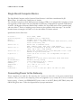
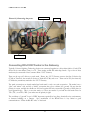
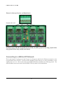
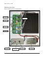
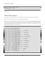
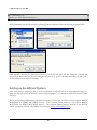
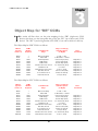
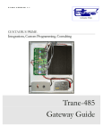
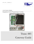
2 / 2 0 1 1 V E R S I O N 1 . 0 CENTAURUS PRIME Integrations, Custom Programming, Consulting “ULT” Gateway Guide 2 / 2 0 1 1 V E R S I O N 1 . 0 INTEGRATIONS, CUSTOM PROGRAMMING, AND CONSULTING “ULT” Gateway Guide 2011 by Centaurus Prime 4425 Cass Street • Suites B-C• San Diego, CA Phone 858.270.4452 • Fax 858.273.7769 www.centaurusprime.com Table of Contents Introduction i CHAPTER 1 “Devices” Menu Options 12 Gateway Installation, Basic Information 1 “Point” Menu Options 13 Summary 1 “Control” Menu Options 15 Single Board Computer Basics 2 “Watch” Menu Options 18 Connecting Power to the Gateway 2 Uploading and Downloading files to the Connecting ULT-Trunks to the Gateway 3 Gateway 20 Connecting To the Modbus Master 4 Setting Up The BACnet System 21 Connecting to a BACnet/IP Network 4 TEMPLATE Files 22 Gateway Overview and Identification 5 CHAPTER 2 CHAPTER 3 Commissioning the Gateway with the Object Map for “DR” CCMs 24 Object Map for “DY” CCMs 24 Index 26 Local user Interface 6 Creating and Downloading the GATEWAY.INI file 6 Creating and Downloading the SOCKET,CFG File 8 Local Mode Menu Options 8 Auto Discovery and Database Generation 8 “Summary” Menu Options 11 C E N T A U R U S P R I M E Chapter 1 Gateway Installation Basic Information Summary T his section will help to give a basic overview and quick summary of the procedures needed to install the “ULT” Gateway Panel. Detailed instructions are also provided later in this guide. The Centaurus Prime “ULT” Gateway allows most any modern front-end system that communicates using the industrystandard BACnet protocols (BACnet/IP, Annex J) to communicate to Universal Lighting Technology DCL controllers (also known as CCMs: Computer Control Modules) field equipment, that use the Modbus protocol. Each of the DCL devices will appear to the front-end system as a series of BACnet Devices. Real time point data from the DCL/CCM controllers is mapped from the registers, coils, and bits that the CCM use as AI, BI, AO, and BO objects on the BACnet system. All operations are transparent to the user and host computer. Connections to the “ULT” Gateway are simple and clearly marked. They are: I C O N K E Y Valuable information • Power Supply, 120 Volts AC (optionally, 220 or 240 Volts AC) • DCL/CCM trunks (up to four; these are RS-485 multi-drop trunks) • BACnet/IP Network (10 megabaud Ethernet connection) • Local Mode Port for commissioning via Laptop Computer All Hardware necessary to connect the Gateway to the ULT devices is included in the 16” X 14” X 8” plastic cabinet that is easily mounted in a convenient location. The BACnet/IP network is a 10-Mbaud Ethernet, only. This is the “routable” BACnet (“Annex J”) protocol, NOT the original non-routable “BACnet over Ethernet” protocol. 1 C E N T A U R U S P R I M E Single Board Computer Basics The Single Board Computer used in Centaurus Prime Gateways is the Ether 6 manufactured by JK Microsystems. It is made in the United States of America. The controller is based on an Intel 386Ex processor running at 25Mhz. It is equipped with 1 megabyte of static ram organized as 512K 16-bit words. Also included are 512K bytes of flash memory organized as DOS drives A and B. A 40 Megabyte M-Systems DiskOnChip is added to the 32-pin DIP socket on the controller board, and acts as drive C: There is a switching power converter on the controller, which can accept 7-34 volts DC. Nominal current consumption is 250mA at 12 volts with 10Base-T Ethernet selected. Specifications for the Ether 6 are: Processor : Operating System : Memory : Ethernet : Serial Port 1 : Serial Port 2 : Serial Port 3-6 : Digital I/O : Watchdog : Clock/Calendar : Supply Power : Humidity : Temperature : Weight : Dimensions : Intel 386Ex, 25MHz XDOS(MS/PC DOS 3.3 compatible) 1M SRAM, 512K Flash, 40MB Flash 10BASE-T, NE2000 compatible automatic media detection, Link status and Activity LEDs RS-232 with 5 handshake lines COM1, address 0x3F8, IRQ4 115200 baud maximum RS-232 no handshaking or RS-485 half duplex, COM2, address 0x2F8, IRQ 3 115200 baud maximum RS-232 with handshake lines, 16554 UART,COM3-6 115200 baud maximum 16 byte Rx and Tx FIFO 5 Bits (P1.4-P1.7 & P3.1) Pin configurable as input or output 8mA souce/sink Hardware, 1.6 second timeout Generates board wide Reset Hardware, battery backup 7-34V unregulated DC ±10%, 3 Watts 5 - 90%, non-condensing -4 to +158 °F (-20 to +70 °C) 53 oz (1.5 kg) 8.30" x 6.76" x 2.28" (210.8mm x 171.7mm x 57.9mm) Connecting Power to the Gateway Power connections are made by first removing the 2 screws on either side of the power terminal block enclosure. Then, you remove the temporary power cord (supplied for you; actually left in from our internal burn-in testing). Connect your PERMANENT power source to the HOT (Black), NEUTRAL (white) and GROUND (green) wires. Follow the diagram below for proper terminations. 2 C E N T A U R U S P R I M E Picture 1.0, Connecting the power 120 Volt Neutral Ground 120 Volt Hot Connecting DCL/CCM-Trunks to the Gateway Typically, Universal Lighting Technology devices are connected together in a daisy-chain fashion. Each CCM device has its own address, from 1 to 63. These trunks are RS-485 multi-drop trunks. Up to four of these trunks may be connected to the Centaurus Prime “ULT” Gateway. There can be up to 63 devices on each trunk. Hence, the “ULT” Gateway reserves the first 63 devices for CCMs on Trunk #1; the second 63 devices to Trunk #2 CCMs, and so on. There can be 252 (four times 63) CCM devices, maximum, attached to the “ULT” Gateway. The trunk connections are clearly marked and each trunk is only a two-wire connection. The trunks have a “plus” and “minus” side, and also a “shield” connection that goes to cabinet (AC) ground. Be sure that the polarity is correct, and that the shields are ALL tied together and only connected to ground at ONE place (to avoid ground-loops). This is a two-wire trunk, so it does not matter if you land the field trunk wires on TX+/TX-, or on RX+/RX-. Just make sure the polarity is right! The avoidance of “ground” loops is VERY important, especially in long lines, electrically noisy environments, or between buildings on a campus. Also, termination of the RS-485 lines is very critical to good communications. Follow the RS-485 “rules” to the letter! 3 C E N T A U R U S P R I M E Picture 1.2, Gateway Overview and Identification Channel A, B, C, & D Installed jumpers: 2W/4W, Baud0, Baud1, Data DCD, Data RTS, J2 (end of line only), J3 (end of line only), J4 (end of line only), and J15 (static bleed) Connecting to a BACnet/IP Network This is quite simple: You plug in an 8-pin Category 5 or Category 6 cable into the Ethernet connection on the top right-hand corner of the PC. You must set the IP address of the Gateway to a static, fixed address, on the segment that you are in. This is done with the GATEWAY.INI file, described in the following section. The same IP address must also be used in the SOCKET.CFG file, which is also described later. 4 C E N T A U R U S P R I M E Gateway Overview Picture 1.3, Gateway Overview and Identification ULT Trunk 4 Single Board Computer ULT Trunk 3 ULT Trunk 2 ULT Trunk 1 On/Off Switch 1 Amp Fuse Remove Cover for Power Connections 5 Power Supply C E N T A U R U S P R I M E Chapter 2 Commissioning the Gateway with the Local User Interface Creating and Downloading the GATEWAY.INI file The following is an example of the GATEWAY.INI file that must be edited to match your particular installation. There are several sets of parameters in the INI file. One set of parameters deals with the BAUD rates on the four ULT trunks. Another parameter sets the Ethernet IP Address of the gateway (it must be a FIXED IP address!), which is used for the BACnet/IP protocol. Also, for BACnet, another set of parameters tells the gateway about several network options of BACnet. The lines for BAUD1, BAUD2, BAUD3, and BAUD4 must be set for the respective CCM Device trunk baud rates which will be “9600” usually, but may be “19200. If you have unused trunks, then the baud rate should be set to “0” as seen in the example below for BAUD3 and BAUD4. See “Uploading and Downloading files to the Gateway” for information on accomplishing the upload/download procedures. The line for IP_ADDR is required for the Ethernet (i.e., BACnet/IP protocol). You have to set up the FIXED IP Address of this gateway computer in two places: here in the GATEWAY.INI file, and also in the SOCKET.CFG file (more on that later). But just be aware that they MUST match! If the SOCKET.CFG specifies a different IP address from the GATEWAY.INI file, you will never receive anything from the Gateway! For the BACnet/IP (Annex J) protocol, a couple other global parameters are necessary. Internally the gateway maps devices in a very simple fashion: Devices 1 through 63 on trunk 1; Devices 64 through 126 on trunk 2, Devices 127 through 189 on trunk 3, and Devices 190 through 252 on trunk 4. But you might not want to use those as your Device “Instance numbers”, if you have some other addressing scheme (or a number of these gateways) on a system. The BACNET_OFFSET allows you to have these devices show up as a different set of Instances rather than just 1 to 252. The number that you specify is added to the internal device number. Hence, if your offset is 5000, and you are interested in (local) device #68 (the fourth gizmo on trunk #2), the BACnet system sees this device as Instance # 5068. Also, if you have multiple gateways on one system, you will need to have each of them be a different Network Number (set via the BACNET_NETWORK parameter in the Gateway.ini file). This is so that there is no confusion between the devices on one gateway and any others (they all could have local device numbers be the same; by having different Network Numbers for each gateway, they become unique, as far as the underlying BACnet protocol works). 6 C E N T A U R U S P R I M E // -------------------------------------------------------------------------// // Required for 4 ports: Set the baud rate (set to 0 if channel unused) // // Valid baud rates are: 4800 – standard Siemens/Landis baud rate // 9600 or 19200 (possibly; newer or non-Siemens) // 0 -- <means that nothing is on that trunk> BAUD1, 4800 BAUD2, 4800 BAUD3, 4800 BAUD4, 0 // // -------------------------------------------------------------------------// // “IP_ADDR” is used for the IP address of what you want this box to be. // ( And it MUST match the SOCKET.CFG IP Address! ) // IP_ADDR, 192.168.0.204 // // -------------------------------------------------------------------------// // “BACNET_NETWORK” is used for what BACnet network number we are on // BACNET_NETWORK, 1042 // // “BACNET_OFFSET” is what we will add to the local device numbers (1..252) // to yield the BACnet object_ID instances of each mapped BACnet “device” // BACNET_OFFSET, 1042000 // Creating and Downloading the SOCKET.CFG file The following is an example of the SOCKET.CFG file that must be edited to match your particular installation, if you are using the Modbus/TCP or BACnet/IP protocols. If you are not doing an Ethernet connection, this text file is irrelevant, and can be ignored and left as it comes from the factory. ONLY ONE LINE SHOULD BE CHANGED—the line that begins with “ip address”. Here is an example: # SOCKET.CFG is the configuration file to be executed by SOCKETP.EXE ip address 192.168.0.204 interface pdr if0 dix 1500 10 0x60 7 C E N T A U R U S P R I M E # The following line will just display the info for easy verification: ip address # The following lines set TCP/IP parameters (commented out in this case): #ip ttl 15 #tcp mss 1460 #tcp window 2920 The “ip address 192.168.0.204” line should be modified to be whatever static IP address that the “ULT” Gateway will have. Note that DHCP is not an option; this device requires a static, fixed, IP address. Local Mode Menu Options Once connected via the local mode port you may press <enter> at any time to display this top level menu: (H)elp, (S)ummary, (D)evice, (P)oint, (C)ontrol, (W)atch, (A)utoDisc, (X)-it When you type “H” <enter> you will get the following: Hit a single key to get to a submenu. Your Options are: H (for Help), which gives you this screen. S (for Summary), which allows you to get various status summaries. D (for Devices), which allows you to manage and get data on devices. P (for Points), which allows you to manage and get data on points. C (for Control), which allows you to control various field objects. W (for Watch), which allows you to watch protocol streams. A (for AutoDisc),which allows you to auto-discover trunks. X (for "X-it"), which exits this gateway program. (H)elp, (S)ummary, (D)evice, (P)oint, (C)ontrol, (W)atch, (A)utoDisc, (X)-it : X – will always take you back to the top level menu options Auto Discovery and Database Generation Before you can use any of the other menu options you must first create your database by using the (A) option, which will give you the following text: AUT: (A)uto-Discovery, (S)ave Discovery, (X)-it :A AUTODISCOVERY: You may select a TRUNK to auto-discover. 8 C E N T A U R U S P R I M E Enter a TRUNK NUMBER (1 through 4) : 1 Trunk #1 will now be auto-discovered... AUT: (A)uto-Discovery, (S)ave Discovery, (X)-it : AutoDiscovery" on Trunk: 1, DCL Device #1 Getting data from CCM... CCM # 1 Discovered on Trunk #1 -- DR CCM "AutoDiscovery" on Trunk: 1, DCL Device #2 CCM # 2 Discovered on Trunk #1 -- DR CCM "AutoDiscovery" on Trunk: 1, DCL Device #3 CCM # 2 Discovered on Trunk #1 -- DY CCM "AutoDiscovery" on Trunk: 1, DCL Device #4 "AutoDiscovery" on Trunk: 1, DCL Device #5 "AutoDiscovery" on Trunk: 1, DCL Device #6 "AutoDiscovery" on Trunk: 1, DCL Device #7 Getting data from CCM... Getting data from CCM... Getting data from CCM... Getting data from CCM... Getting data from CCM... Getting data from CCM... Etc… "AutoDiscovery" on Trunk: 1, DCL Device #62 Getting data from CCM... "AutoDiscovery" on Trunk: 1, DCL Device #63 Getting data from CCM... State: “AutoDiscovery” on Trunk 1, COMPLETED! When Auto Discover is invoked the Gateway will scan for all CCM device addresses possible on the requested trunk. As you can see in the example above, “CCM” Device address #1 and #2 were discovered, which were both “DR” type controllers. Note that a “DY” type CCM device was discovered at address #3. This process should be completed for all trunks that have “ULT” devices. When all trunks have been Auto Discovered, you can then use the (S)ave Discovery option. Note 1: This is a lengthy process, taking 3-4 minutes per trunk on a 9600-baud trunk. Be patient--wait for it to complete! (Coffee is always good, here) Note 2: If a controller is dead, unplugged, or not communicating when Auto-Discover is done, you can manually add the controller to the discovered data file. You must download the data file to your PC, edit it to add a line about the missing controller, and then upload the modified file back into the Gateway. See “Uploading and Downloading files to the Gateway” Note 3: Files that are in the Gateway on drive C:, and their purpose, are: STARTUP .BAT GATEWAY.INI SOCKET.CFG - Startup Batch file - Sets all baud rates, IP Address, BACnet parameters - IP Configuration file 9 C E N T A U R U S P R I M E SOCKETP .EXE - TCP/IP Socket stack NE2000.COM - Ethernet Driver ULT_GWAY.EXE - Does all the magic DATABASE.DAT - Database that is created from Save Discovery DISC_1 .TXT - Trunk #1 Auto Disc File DISC_2 .TXT - Trunk #2 Auto Disc File DISC_3 .TXT - Trunk #3 Auto Disc File DISC_4 .TXT - Trunk #4 Auto Disc File CONFIG .TXT - Device configuration file created when the Auto-Discovery files are merged XPING.EXE - Test program to verify Ethernet connectivity WATCHDOG.TXT - Only exists if you want the Gateway to reboot if ALL trunk communications fails. (H)elp, (S)ummary, (D)evice, (P)oint, (C)ontrol, (W)atch, (A)utoDisc, (X)-it :A AUT: (A)uto-Discovery, (S)ave Discovery, (X)-it :S AUTODISCOVERY: You may SAVE and MERGE all trunk auto-discovery maps. ARE YOU SURE? If so, enter "Y" for YES; and then the ENTER key. (or any other keys if you do NOT want to merge the maps :Y Discovery File Merging, trunk #1 Merging ULT unit #1, Trunk #1; Device #1 Type: DR Merging ULT unit #2, Trunk #1; Device #2 Type: DR Merging ULT unit #3, Trunk #1; Device #3 Type: DY Discovery File Merging, trunk #2 Merging ULT unit #1, Trunk #2; Device #64 Type: DY Merging ULT unit #2, Trunk #2; Device #65 Type: DY Merging ULT unit #3, Trunk #2; Device #66 Type: DY Merging ULT unit #4, Trunk #2; Device #67 Type: DY Discovery File Merging, trunk #3 Merging, ULT unit #1; Trunk #3; Device #127 Type: DR Merging, ULT unit #2; Trunk #3; Device #128 Type: DR No Discovery File on trunk #4 This option will merge all of the discovery files for each trunk thereby giving you a completed database for the CCM devices on all “ULT” trunks. After the merge is complete, the Gateway will have created a file called CONFIG.TXT. When the Gateway is rebooted, this new Database Configuration file will be initialized and communications to the field devices will commence. 10 C E N T A U R U S P R I M E The Save Discovery option automatically assigns BACnet device numbers to the CCM devices it finds, in order. First, devices on trunk #1 are assigned, in order of Modbus slave devices (that is, the settings of the CCMs) 1 through 63 (note that there are a maximum of 63 CCM devices for EACH trunk – this is the limitation of the Universal Lighting Technology’s Modbus protocol implementation). Similarly, the ULT devices found on Trunk #2 are assigned (in the order that they are discovered) to BACnet device numbers 64 through 126. And of course, BACnet device numbers 127 to 189 are for the CCM devices found on Trunk #3, and finally BACnet device numbers 190 to 252 are assigned to P1 devices on Trunk #4 (in order of discovery). “Summary” Menu Options SUM: (D)evices, (A)larms, (C)ontrolled, (U)nreliable, (X)-it : After the (S)ave Discovery has been completed, you can then reboot and the Gateway will begin to poll the discovered devices. The summary menu option will display further options detailed below. (D)evices : Devices will display all the status of all devices configured for the Gateway. SUM: (D)evices, (A)larms, (C)ontrolled, (U)nreliable, (X)-it :D # 1 TagID: "DCL #1, Trunk 1 (BACnet #1)" is ON-LINE & RELIABLE # 2 TagID: "DCL #2, Trunk 1 (BACnet #2)" is ON-LINE & RELIABLE # 64 TagID: "DCL #1, Trunk 2 (BACnet #64)" is OFF-LINE! <MUST INIT> (SlowScan) # 65 TagID: "DCL #2, Trunk 2 (BACnet #65)" is ON-LINE & RELIABLE # 66 TagID: "DCL #3, Trunk 2 (BACnet #66)" is ON-LINE & RELIABLE # 67 TagID: "DCL #4, Trunk 2 (BACnet #67)" is ON-LINE & RELIABLE #127 TagID: "DCL #1, Trunk 3 (BACnet #127)" is ON-LINE & RELIABLE #128 TagID: "DCL #2, Trunk 3 (BACnet #128)" is ON-LINE & RELIABLE (A)larms: With BACnet, this does have meaning, but only for points that have alarm states or limits (intrinsic alarms) defined. At the present time, the Centaurus Prime gateways do NOT support BACnet alarming, either “intrinsic” or “algorithmic”. (C)ontrolled: This command will display all controlled points for all BACnet devices. SUM: (D)evices, (A)larms, (C)ontrolled, (U)nreliable, (X)-it :C Internal Global Controls Queue: Head = 987 Tail = 987; Controls Today = 1529 *** Gateway has NO controls to do! *** 11 C E N T A U R U S P R I M E This is the usual condition of the gateway. If you have a bunch of controls that happen at a particular time, you may be able to catch the gateway with some controls that it needs to do. In that case, it will list all the objects in the queue that need to be controlled, and what those controls are. The “head and tail” numbers will then be different, too. If you find that the gateway has lots of controls to do, or the number of controls keeps building up, you have some run-away logic external to the gateway which is over-controlling! (U)nreliable: This will display all unreliable points for all devices. SUM: (D)evices, (A)larms, (C)ontrolled, (U)nreliable, (X)-it :U DEVICE #1 is field device/subdevice/type 1/0/0 --BACnet ID 4 (AI) RCPU TEMP is UNRELIABLE DEVICE #64 is field device/subdevice/type /0/16936 ***** DEVICE is OFF-LINE (All points under it are “unreliable”) “Devices” Menu Options The Devices menu is used to display all of the configured devices (A) or to “target” a specific device and get data about it. (S)elect: Target a specific device. This allows you to work with ONE device, rather than them all. This is the FIRST thing you do when you want to look at one point, on one device, or control a point. First, you select the device, then go to the POINT menu, to select the point. (And if you want to control it, then go to the CONTROL menu, and issue controls to it) Here’s how you would select device #2 (the second device on trunk #1): DEV: (S)elect, (A)ll, (D)etail, (O)ff-line, (C)omm Stats, (X)-it :S DEV: You may select a DEVICE to target into. Enter a DEVICE number (1..240 or 0 for all): 2 Device #2 is now the targeted device. (A)ll: View all configured devices. This is just a summary of the current status of all devices. In the following example, Device #62 is dead, but all the others are doing just fine: DEV: (S)elect, (A)ll, (D)etail, (O)ff-line, (C)omm Stats, (X)-it :A # 1 TagID: "DCL #1, Trunk 1 (BACnet #1)" is ON-LINE & RELIABLE # 2 TagID: "DCL #2, Trunk 1 (BACnet #2)" is ON-LINE & RELIABLE # 64 TagID: "DCL #1, Trunk 2 (BACnet #64)" is OFF-LINE! <MUST INIT> (SlowScan) 12 C E N T A U R U S P R I M E # 65 TagID: "DCL #2, Trunk 2 (BACnet #65)" is ON-LINE & RELIABLE # 66 TagID: "DCL #3, Trunk 2 (BACnet #66)" is ON-LINE & RELIABLE # 67 TagID: "DCL #4, Trunk 2 (BACnet #67)" is ON-LINE & RELIABLE #127 TagID: "DCL #1, Trunk 3 (BACnet #127)" is ON-LINE & RELIABLE #128 TagID: "DCL #2, Trunk 3 (BACnet #128)" is ON-LINE & RELIABLE (D)etail: Will display the following details of selected device. DEV: (S)elect, (A)ll, (D)etail, (O)ff-line, (C)omm Stats, (X)-it :D DEVICE #2 is field device/subdevice/type 1/0/2092 Device Name: DCM #1; Trunk 1 (BACnet #1) Device Description: CCM #1 on Trunk #1 Location: West Conference Room # 1 TagID: "DCM #1; Trunk 1 (BACnet #1)" is ON-LINE & RELIABLE I/O Trunk: 1, had last COMM at 17:13:12 on Jan 28, 2011 Scan time (secs): 42. Device has 14 objects under it. First link =54 (O)ffline: This will display the Offline status of devices. Hopefully none are, but if any are, they will be displayed in a list. DEV: (S)elect, (A)ll, (D)etail, (O)ff-line, (C)omm Stats, (X)-it :O # 64 TagID: "DCL #1, Trunk 2 (BACnet #64)" is OFF-LINE! <MUST INIT> (SlowScan) (C)omm Stats: This will display communication statistics of the selected device. DEV: (S)elect, (A)ll, (D)etail, (O)ff-line, (C)omm Stats, (X)-it :C # 1 TagID: "DCM #1; Trunk 1 (BACnet #1)" statistics: Packets Today: 101902 RX Errors Today: 92 % Error: 0.090 TX Errors Today: 509 % Error: 0.499 Last Comm at: 17:13:26 on Jan 28, 2011 “Point” Menu Options The “Point” menu has three options, Select, All, and Detail. PNT: (S)elect, (A)ll, (D)etail, (X)-it : 13 C E N T A U R U S P R I M E (A)ll: This will display all points and their current values for the targeted device. What follows below is an example from a “DR” type device attached to the Gateway: PNT: (S)elect, (A)ll, (D)etail, (X)-it :A TagID: "DCM #1; Trunk 1 (BACnet #1)", has 14 objects under it, 1st one at: 14 --BACnet ID 45 (AO) " Zone-A Fade Index" Fld: 0 ==> 0.00 --BACnet ID 44 (AO) " Zone-A Scene Index" Fld: 0 ==> 0.00 --BACnet ID 43 (AO) " Zone-A Fade Rate" Fld: 0 ==> 0.00 --BACnet ID 42 (AO) " Zone-A Desired Pwr Lvl" Fld: 100 ==> 100.00 --BACnet ID 25 (AI) " CCM Error Code" Fld: 0 ==> 0.00 --BACnet ID 24 (AI) " Zone-A Power Level" Fld: 100 ==> 100.00 --BACnet ID 23 (AI) " CCM Amperage" Fld: 1018 ==> 0.13 --BACnet ID 22 (AI) " CCM Voltage" Fld: 640 ==> 117.57 --BACnet ID 21 (AI) " CCM Temperature" Fld: 221 ==> 63.85 --BACnet ID 2 (BI) " Power LED Status" Fld: 1 ==> GREEN --BACnet ID 1 (BO) " Relay Control" Fld: 1 ==> ON --BACnet ID 203 (AV) " K-Packets TX/RX Today" Fld: 3 ==> 3.15 --BACnet ID 204 (AV) " TX Error Rate" Fld: 0 ==> 0.00 --BACnet ID 205 (AV) " RX Error Rate" Fld: 0 ==> 0.00 (S)elect: With Select, you can target a specific point for the Device that you have targeted using the “Devices” menu. This, along with the DEVICE that you have selected, now uniquely defines a point of interest to you. You have to select the object TYPE and ID for BACnet, to uniquely specify an object. An example: PNT: (S)elect, (A)ll, (D)etail, (X)-it :S PNT: You may select an OBJECT ID to target into. Enter an existing BACnet Object TYPE/ID (0 to 4, 1 to 1000) : 0, 1 The object with TYPE 0 and Object ID #1is now selected. You have to remember that BACnet types are an “enumerated value” (in BACnet-speak). These are, for those who don’t remember such minutae: • • • • • 0 = AI 1 = AO 2 = AV 3 = BI 4 = BO 14 C E N T A U R U S P R I M E (D)etail: will display details associated with the selected point, for BACnet points, in a format like this: PNT: (S)elect, (A)ll, (D)etail, (X)-it :D BACnet Object ID = 1, Type = BO Object Name: “Relay Control” Description: “Main Relay Control” …No elements in priority/control array …BACnet Relinquish Default Value: NULL Field Unit / Subunit : 42 / 0 Field Address :1 Object Flags / Errors : 3 / 0 Field In / Out Counts : 1 / 0 Field Value : 1.000 Field Lo / Hi Range : 0.000 / 1.000 Eng. Units : OFF / ON “Control” Menu Options In BACnet, you control things at sixteen different priority levels, and you can “release” control from any particular level. Now, before you can control a point object you must first have selected a device number and point number (see the point map, Chapter 3). (S)elect: Use this to select a valid point. Here is an example, selecting AO #42 (the Zone-A Desired power level): CTL: (S)elect, (P)riority, (C)ontrol, (R)elease, (D)etail, (X)-it :S CTL: You may select an OBJECT ID to target into. Enter a valid, existing, BACnet Object TYPE/ID (0 to 4), (1 to 16000): 1,42 The object with Type 1 and Instance #142 is now selected. (C)ontrol:. This option will let you control the selected point. Here is a simple example of a digital point control to “off” (zero ); for example, this might be BO #1, the main relay control: CTL: (S)elect, (C)ontrol, (D)etail, (X)-it :C CTL: You may enter a new value to set the selected object to. Enter a field value (0 or 1 for digitals; valid number for analogs) : 0 15 C E N T A U R U S P R I M E The new value of the object will be : 0 (P)riority: (BACnet ONLY) Use this to select the priority that you will issue subsequent control and release operations at. CTL: (S)elect, (P)riority, (C)ontrol, (R)elease, (D)etail, (X)-it :P PRI: Enter a PRIORITY to do your controls at (1 to 16): 4 Control and Release Operations will now be done at Priority 4. Now let’s talk about BACnet (alias BADnet) priorities for a bit. There are sixteen priorities. These are given below: Priority 1 2 3 4 5 6 7 8 9 10 11 12 13 14 15 16 BACnet Default Manual Life-Safety Automatic Life-Safety Miscellaneous Miscellaneous Critical Equipment Control Minimum On/Off Custom Programming—High Manual Operator VAV Air Systems Chiller Plant Control Area Control Manual Operator—Low Miscellaneous Timed-Override Time-of-Day Scheduling Custom Programming—Low N/A Relinquish Default Comments User-Emergency use only! Critical! (Programmatic; no mins) Commonly: Demand Limiting Commonly: “Minimum on/off” Custom Programming—High Pri. Standard “Operator Control” Commonly: VAV “group” control Usually Chiller Plant Control Usually: Area Control (non-VAV) Infrequently used Overrides a “standard” schedule Time-of-Day Scheduling Custom Programming—Low Pri. Relinquish Default Note in the “Comments” we have given what the majority of control systems use for their “Default” was for the priorities in question. This is informational only, but might help. Each controllable point in BACnet (that is, an AO or a BO) has a “priority array” which is generally sparsely populated. Nothing in a particular priority level is specified by “Null”, which means that priority level is unused. 16 C E N T A U R U S P R I M E As an example, consider a warehouse exhaust fan which is turned on and off by a time schedule at priority 15. In a demand-limiting situation, this point may also have control at priority 5 (shut down ancillary systems in energy peak situations). But programmatically, a logic block that detects a fire might want to override everything and keep the fan on in order to pressurize an area and keep the fire from spreading, so that might be at priority 2. When control is “released” from the higher levels, the next lowest control is issued. Hence, after the fire is over, the fan that was overridden ON might go OFF from its priority 7 demand-limiting shutdown. But if that priority 7 control had been released, then the control descends to the priority 15 time-schedule control. You have to know what your plant’s priority system is, and what each point’s capabilities and control options are—this is not a trivial control philosophy! The “Relinquish Default” value, if any is specified, is the control that is given out to a point if there is NOTHING in this priority array (that is, all 16 levels of control have been released). If there is no “Relinquish Default” value (i.e., “NULL”), then the point just sits there, at it’s last control. Now, before you can control a point object you must first have selected a device number , a point type/instance, and a priority. Then you can set the control value, and that value will go into the object’s priority-array. That does NOT mean that control will be issued, remember, since you may be at a lower priority level than what is controlling the point right now. (R)elease: This option will let you release control for the selected point at your selected priority level: CTL: (S)elect, (P)riority, (C)ontrol, (R)elease, (D)etail, (X)-it :R RLS: Are you sure that you want to RELEASE this object? ARE YOU SURE? If so, enter Y for Yes, and then the ENTER key. (or any other keys if you do NOT want to RELEASE the object) : Y The object AO #114 has been released from Priority #4. (D)etail: will display details associated with the selected point.. Let’s first look at a Modbus version of an object’s detail: CTL: (S)elect, (P)riority, (C)ontrol, (R)elease, (D)etail, (X)-it :D BACnet Obj_ID 44, Type = AO Object Name: “Zone-A Scene Index” Description: “Zone-A Scene Index (0-28)” …No elements in priority/control array …BACnet Relinquish Default Value: 65.000 Field Unit / Subunit : 4 / 0 Field Address :40044 Object Flags / Errors : 0 / 0 Field In / Out Counts : 7 / 7 Field Value : 7.000 17 C E N T A U R U S P R I M E Field Hi / Lo Range : 0.000 / 4095.000 Engineering Units : UNITS Had any priorities have controls in them, it would have displayed the priority and the control value, for EACH priority level. “Watch” Menu Options The “Watch” menu will let you select various methods for monitoring the real time data from the field. (Q)uiet: Use the (Q) key to halt any of the following monitoring options. (1),(2),(3),(4) to Watch Trunks: Enter the number of a P1 trunk to monitor (1-4). This will display the field scan of all Trunk devices and the status of their points in real time. What is displayed below is the Modbus variant (it shows the register numbers in the second column); the BACnet variation is the same except it shows the BACnet object instances in the second column: WCH: (Q)uiet, (1),(2),(3),(4) to watch trunks; (V)erbose, (M)odbus, (X)-it :1 *** TRUNK 1 is now being MONITORED *** SCAN --- Device: 1 DCL #1 Register: 40045 1(BC # 1) AO 45 Zone-A Fade Index Field: 0 = 0.00 UNITS SCAN --- Device: 1 DCL #1 Register: 40044 1(BC # 1) AO 44 Zone-A Scene Index Field: 0 = 0.00 UNITS SCAN --- Device: 1 DCL #1 Register: 40043 1(BC # 1) AO 43 Zone-A Fade Rate Field: 0 = 0.00 SECNDS SCAN --- Device: 1 DCL #1 Register: 40042 1(BC # 1) AO 42 Zone-A Desired Pwr Lvl Field: 100 = 100.00 PERCNT SCAN --- Device: 1 DCL #1 Register: 30025 1(BC # 1) AI 25 CCM Error Code Field: 0 = 0.00 CODE SCAN --- Device: 1 DCL #1 Register: 30024 1(BC # 1) AI 24 Zone-A Power Level Field: 100 = 100.00 PERCNT SCAN --- Device: 1 DCL #1 Register: 30023 1(BC # 1) AI 23 CCM Amperage Field: 1018 = 0.13 AMPS SCAN --- Device: 1 DCL #1 Register: 30022 1(BC # 1) AI 22 CCM Voltage Field: 638 = 118.22 VOLTS SCAN --- Device: 1 DCL #1 Register: 30021 1(BC # 1) AI 21 CCM Temperature Field: 219 = 70.90 DEG F SCAN --- Device: 1 DCL #1 Register: 2 1(BC # 1) BI 2 Power LED Status Field: 1 = GREEN SCAN --- Device: 1 DCL #1 Register: 1 1(BC # 1) BO 1 Relay Control Field: 1 = ON 18 C E N T A U R U S P R I M E ...etc… (V)erbose: When (V) is pressed while in monitor mode, the full protocol data packets will be displayed as well for each scanned device. Here’s another partial example: *** Now in VERBOSE MODE (full packets) for monitored trunks 1->> To: 02 03 00 2C 00 01 45 F0 <Read Holding Regs, from 40045> 1<<- Frm: 02 03 02 00 02 7D 85 2(BC # 2) AO 45 Zone-A Fade Index Field: 2 = 2.00 UNITS SCAN --- Device: 2 DCL #2 Register: 40044 1->> To: 02 03 00 2B 00 01 F4 31 <Read Holding Regs, from 40044> 1<<- Frm: 02 03 02 00 00 FC 44 2(BC # 2) AO 44 Zone-A Scene Index Field: 0 = 0.00 UNITS SCAN --- Device: 2 DCL #2 Register: 40043 1->> To: 02 03 00 2A 00 01 A5 F1 <Read Holding Regs, from 40043> 1<<- Frm: 02 03 02 00 0A 7C 43 2(BC # 2) AO 43 Zone-A Fade Rate Field: 10 = 10.00 SECNDS SCAN --- Device: 2 DCL #2 Register: 40042 1->> To: 02 03 00 29 00 01 55 F1 <Read Holding Regs, from 40042> 1<<- Frm: 02 03 02 00 2C FD 99 2(BC # 2) AO 42 Zone-A Desired Pwr Lvl Field: 44 = 44.00 PERCNT SCAN --- Device: 2 DCL #2 Register: 30025 1->> To: 02 04 00 18 00 01 B1 FE <Read Input Regs, from 30025> 1<<- Frm: 02 04 02 00 00 FD 30 2(BC # 2) AI 25 CCM Error Code Field: 0 = 0.00 CODE SCAN --- Device: 2 DCL #2 Register: 30024 1->> To: 02 04 00 17 00 01 81 FD <Read Input Regs, from 30024> 1<<- Frm: 02 04 02 00 64 FC DB 2(BC # 2) AI 24 Zone-A Power Level Field: 100 = 100.00 PERCNT SCAN --- Device: 2 DCL #2 Register: 30023 1->> To: 02 04 00 16 00 01 D0 3D <Read Input Regs, from 30023> 1<<- Frm: 02 04 02 03 FA 7D 83 2(BC # 2) AI 23 CCM Amperage Field: 1018 = 0.13 AMPS <new> SCAN --- Device: 2 DCL #2 Register: 30022 1->> To: 02 04 00 15 00 01 20 3D <Read Input Regs, from 30022> 1<<- Frm: 02 04 02 02 82 7C 31 2(BC # 2) AI 22 CCM Voltage Field: 642 = 116.91 VOLTS SCAN --- Device: 2 DCL #2 Register: 30021 1->> To: 02 04 00 14 00 01 71 FD <Read Input Regs, from 30021> 1<<- Frm: 02 04 02 00 DC FC A9 2(BC # 2) AI 21 CCM Temperature Field: 220 = 67.38 DEG F …etc… 19 <new> C E N T A U R U S P R I M E (B)ACnet: When (B) is pressed while in monitor mode, the full BACnet protocol data packets (addressed globally or to this gateway only) will be displayed in real-time. Note that this significantly slows down the BACnet channel, and we recommend that this mode NOT be utilized for any length of time. Uploading and Downloading files to the Gateway In order to upload/download files to the Gateway, you will need to use a VT-100 Terminal emulator (Hyperterminal or the like). You will need to set it up to use a Comm Port (Comm1 typically) and use the following settings: Baud=9600, Databits=8, Stop bits=1, Parity=None, and no Flow Control. The Gateway has two utilities for transferring files. UP.COM is used to send files to the Gateway and DOWN.COM is used to received files from the gateway. When you are connected to the gateway in local mode, hit X-it once or twice and you will be asked to type “YES” to quit the program which will take you to DOS prompt. Sending a file to the Gateway (uploading) From the dos prompt, you must type “UP filename” (filename being the name of the file to send with extension). The response will look like the following. C:\>up test.txt Ready, start X-modem upload now, Press CNTL-C to abort... …… In Hyperterminal, start the file transfer by selecting Transfer/Send and follow the following sequence below. Click Transfer > Send File: Browse for file to send and make sure that Xmodem is selected. Click the send button and the file will be sent to the Gateway. Receiving a file from the Gateway (downloading) From the dos prompt, you must type “DOWN filename” (filename being the name of the file to receive with extension). The response will look like the following. 20 C E N T A U R U S P R I M E C:\>down disc_1.txt Ready, start X-modem download now... In Hyperterminal, start the file transfer by selecting Transfer/Send and follow the following sequence below. Click Transfer > Receive File: Enter the location to save the file and make sure that Xmodem is selected and then click the Receive button. The next dialog box will ask you to specify a filename and when you click “OK” the file will be received from the Gateway. Setting up the BACnet System After the Gateway is ready to go and you have your database configured, one of the most important steps is to make sure that you have your BACnet system configured properly to communicate with the Centaurus Prime Gateway. The most important parameter that some BACnet systems need to know is whether a device supports READMULTIPLE and WRITE-MULTIPLE services. The Centaurus Prime Gateways only support READMULTIPLE, not WRITE-MULTIPLE services. All Centaurus Prime Gateways conform to the BACnet “PICS” statement published and available on our web site, www.CentaurusPrime.com. 21 C E N T A U R U S P R I M E There is some difference in the way many host systems work. Some require our gateway to be on a separate network number (e.g., Jace, ALC); some prefer the gateway to be on the same network (e.g., Alerton), and some don’t care (most). In the GATEWAY.INI you should change the parameter “BACNET_NETWORK” to an appropriate value. Typically, installers have chosen the BACNET_NETWORK to be a certain number, and then made the BACNET_OFFSET to be 1000 times that number; so that the BACnet instance numbers of the devices are all prefixed by the network number. As an example, if you set the BACNET_NETWORK number to 333 and the BACNET_OFFSET to 333000, then you would end up with BACnet device numbers 333001, 333002, 333003, etc., on network #333. Makes it simple, no? Just a suggestion! DO NOT over-tax the BACnet network! At about 30 BACnet/IP packets per second directed TO THE GATEWAY, the Gateway will saturate; any more packets than that, and they are lost. Any more than that will cause retries and actually SLOW DOWN the BACnet system! This is because BACnet/IP is a “connectionless” system—the requestor sends a packet to the Gateway, and the network gives it a “best effort” to deliver it. If the network is saturated, and our Gateway does not receive the packet, the requestor has to time-out, and then retries its request packet. This may mean that control logic will “stall” (depending upon the software implementation in the controller) until that retry occurs. TEMPLATE Files An added feature of the Centaurus Prime Gateways is that you can set up “Templates”. The default naming and ranges are adequate for most applications. But perhaps you don’t like English (American) units, and want to “Go Metric”. Or you might want to change the names of all the objects, because you have a particularly fussy user, with a specific naming convention for their site. You would then need to download to the Gateway any “regular” and/or “custom” templates that will be used in your building. Say that you had a system with a specific naming convention, and they didn’t want to bring out the Fade Index or Scene Index. You would need to create a template (let’s do an example: // Application for my building with special name; no Fade Index or Scene Index // //Type, Point, ID-Name, 0-Units/Zero, 1-Units/Range, Ana.-Units, Full-Name, Comments // BO, 1, Main Control, OFF, ON, , Primary Relay for CCM , BI, 2, Power LED State, OFF, ON, , LED Status , Red is “off” AI, 21, CCM Temperature, 0.0, 4095.0, DEG F, Room Temperature , AI, 22, CCM Voltage, 0.0, 4095.0, VOLTS, CCM Voltage , AI, 23, CCM Current, 0.0, 4095.0, AMPS, CCM Current Usage , AI, 24, Zone-A Power Level, 0.0, 4095.0, PERCENT, Power Level in Zone-A , instantaneous AI, 25, CCM Error-Code, 0.0, 4095.0, UNITS, Error-Code from CCM , OK = 0 AO, 42, Zone-A Power CMD, 0.0, 4095.0, PERCENT, Command Power in Zone-A , desired power AO, 43, Zone-A Fade-Rate, 0.0, 4095.0, SECONDS, Fade-Rate in Zone-A , secs/unit-change One philosophy is to put all points in the Gateway (i.e., either use the “defaults”, or use template files with all points, and download them to the Gateway), and just NOT map the ones that you don’t want. The other philosophy is to DELETE the points you will never want to expose from these template files, before you download them to the Gateways. The good point of the first philosophy is that all the points are there, if you 22 C E N T A U R U S P R I M E ever want to map them later; the bad news is that the Gateway has to scan these points, and that affects performance in a bad way. The good point of the second philosophy is that the scan is quicker, and you are only getting the data you want; the bad news is that if you want to add points in the future, you will need to download modified TEMPLATE files to the Gateway in order to add those points. Note that what you are doing is sending down “custom” templates for a particular device. They are named simply, “TPL_x_yy.CSV”, where “x” is the trunk number, and “yy” is the CCM unit number. Hence, for CCM #15 on Trunk #2, and we would create a special “custom template” called “TPL_2_15.CSV” (the “2” being for trunk #2, the “15” being for CCM #15 By downloading these custom files to the Gateway, you can get the Gateway to use them for a certain ULT device on a particular trunk, instead of the “standard” template for that application. How sweet it is! You can customize the system to your heart’s desire! 23 C E N T A U R U S P R I M E Chapter 3 Object Map for “DR” CCMs T his section will first show you the point mapping for the “DR” (single-zone) CCM devices, then show you the extra points that go into the “DY” (up to three zones) CCM devices. The “DY” is just the big-brother of the “DR”, if you want to think of it that way. The Object Map for “DR” CCMs is as follows: BACnet Type and Instance # CCM’s Modbus Register # Point Name and Usage Range ( for Analogs) State Descriptions (for Digital) BO #1 BI #2 AI #21 AI #22 AI #23 AI #24 AI #25 AO #42 AO #43 AO #44 AO #45 1 2 30021 30022 30023 30024 30025 40042 40043 40044 40045 Main Control Relay Power LED CCM Temperature CCM Voltage CCM Current Current Power Level, Zone-A CCM Error Code Desired Power level, Zone-A Fade Rate, Zone-A Scene Index, Zone-A Fade Index, Zone-A 0 = Off; 1 = On 0 = Abnormal; 1 = Normal Custom; Deg F. (fixed) Custom; Volts(fixed) Custom; Amps (fixed) 0 to 100 Percent (fixed) 0 = normal 0-100 % (fixed) 0-127 Seconds (fixed) 0-28 (Scene #, fixed) 0-14 (also fixed) Notes & Comments Range Note 1 Range Note 1 Range Note 1 Range Note 2 Range Note 3 Range Note 2 Range Note 2 Range Note 2 Range Note 2 The Object Map for “DY” CCMs is as follows: BACnet Type and Instance # CCM’s Modbus Register # Point Name and Usage Range ( for Analogs) State Descriptions (for Digital) BO #1 BI #2 AI #21 AI #22 AI #23 AI #24 AI #25 AO #42 AO #43 AO #44 AO #45 AI #124 AO #142 1 2 30021 30022 30023 30024 30025 40042 40043 40044 40045 30124 40142 Main Control Relay Power LED CCM Temperature CCM Voltage CCM Current Current Power Level, Zone-A CCM Error Code Desired Power level, Zone-A Fade Rate, Zone-A Scene Index, Zone-A Fade Index, Zone-A Current Power Level, Zone-B Desired Power level, Zone-B 0 = Off; 1 = On 0 = Abnormal; 1 = Normal Custom; Deg F. (fixed) Custom; Volts(fixed) Custom; Amps (fixed) 0 to 100 Percent (fixed) 0 = normal 0-100 % (fixed) 0-127 Seconds (fixed) 0-28 (Scene #, fixed) 0-14 (also fixed) 0 to 100 Percent (fixed) 0-100 % (fixed) 24 Notes & Comments Range Note 1 Range Note 1 Range Note 1 Range Note 2 Range Note 3 Range Note 2 Range Note 2 Range Note 2 Range Note 2 Range Note 2 Range Note 2 AO #143 AO #144 AO #145 AI #224 AO #242 AO #243 AO #244 AO #245 40143 40144 40145 30224 40242 40243 40244 40245 Fade Rate, Zone-B Scene Index, Zone-B Fade Index, Zone-B Current Power Level, Zone-C Desired Power level, Zone-C Fade Rate, Zone-C Scene Index, Zone-C Fade Index, Zone-C 0-127 Seconds (fixed) 0-28 (Scene #, fixed) 0-14 (also fixed) 0 to 100 Percent (fixed) 0-100 % (fixed) 0-127 Seconds (fixed) 0-28 (Scene #, fixed) 0-14 (also fixed) Range Note 2 Range Note 2 Range Note 2 Range Note 2 Range Note 2 Range Note 2 Range Note 2 Range Note 2 NOTE 1: The Temperature, Current, and Voltage are custom calculations from the raw A/D value that the CCM returns. The range cannot be changed. NOTE 2: The Power levels (both desired and current) are always 0 to 100 percent, and cannot be changed in the CCM. Also, the Fade Rate is in seconds (a multiplier: This value times the stepchange is the total time it takes to get from one power level to another). The Fade Index and Scene Index are just numbers, which relate to the pre-programmed Fades and Scenes within the CCM. NOTE 3: The Error-code is described in great detail in “Table 3” of the MC20DCLUNV Protocol document. It is shown here, for your convenience, but the detail in the Universal Lighting Technologies document is more detailed: Value = 0 Value = 1 Value = 2 Value = 3 Value = 4 Value = 5 Value = 6 Value = 7 Value = 8 Value = 9 Value = 10 Value = 11 Value = 12 No error (good news) Power_ON or Watchdog-timer reset (LED is solid red; does not blink) Heart-Beat timeout (CCM did not get anything from Gateway) Over Temperature (not used; can “never” happen) Erase Error (CCM could not erase it’s internal memory) Data Overrun (problem on communication port in CCM) Bad Relay event (internal CCM failure) Bad Command (should never happen, but might occur) Bad Timer units (internal firmware error) Write Error (something wrong with CCM microprocessor) Missing Zero-Crossing (Line voltage problem) Low-voltage detected; Microprocessor has been reset (hardware error) Serial number programming fault (software error) 25 Index (A)larms, 11, 12 Downloading, i, 6, 7, 9, 20 (C)ontrol, 8, 10, 15, 16, 17 Gateway Overview, 5 (C)ontrolled, 11, 12 jumpers, 4 (D)etail, 12, 13, 14, 15, 16, 17 Local Mode, 8 (D)evices, 11 Memory, 2 (H)elp, 8 Modbus Master, i, 4 (M)odbus, 18 Power, 2, 3 (S)elect, 12, 13, 14, 15, 16, 17 Power Supply, 1 (V)erbose, 18, 19 Processor, 2 “Devices” Menu Options, 12 Receive File, 21 “Point” Menu Options, 13 RS-232, 2 “Summary” Menu Options, 11 Send File, 20 220 or 240 Volts AC, 1 Serial Port, 2 Auto Discovery, 8 Setting up the BACnet System, 21, 22 BAUD.TXT, i, 6 Smart II Device Buss, 1 Commissioning, 6 SOCKET.CFG, 7 communication statistics, 13 targeted device, 14 Creating and Downloading the GATEWAY.INI Uploading, i, 6, 9, 20 file, 6 Watch, i, 8, 18 Database Generation, 8 26