1
2
7
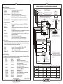
Modes Of Operation:
1. Three Preset RPM High Idle Modes:
Function:
Increase idle to a preset rpm value
Terminals:
RPM1, RPM2, RPM3
Activation:
Apply +12 V to terminal
Range of Calibration: 900 to 2250 rpm (gas engines)
1200 to 2300 rpm (2005 - 2010 diesel engine)
900 to 3000 rpm (2011 and later diesel engine)
Enable:
Disengage:
RPM Range:
PTO
GEAR
On Solid
GEAR
Flashing
PK BRK
PK BRK
SR BRK
SR BRK
VSPEED
VSPEED
On Solid
Flashing
On Solid
Flashing
On Solid
Flashing
Indication
Module ON and functioning
Module ON, but a problem with CAN
bus communications
Transmission in PARK position or
Clutch Pedal released
Transmission not in PARK position or
Clutch Pedal activated
Park Brake set
Park Brake not set
Service Brake at rest (not activated)
Service Brake activated
Vehicle stationary
Vehicle moving
ETM51 OM-54H
Ground
GND
InPower
ETM51
REF
RPM1
CANL
CANH
Shield
CANH (Yellow)
RPM2
RPM3
Yellow
Green
VRPM
1 2 3 4 5 6 7 8
9 10 11 12 13 14 15 16
CANL (Green)
View looking into OBD-II connector
located on lower dash on drivers side.
Customer To Supply
Fast Idle
RPM 1
On
RPM 2
*
Off
RPM 3
*
Status Indicators
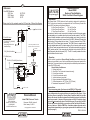
A 10 segment LED provides status and problem detection information. Refer
to the following table for coding of these functions.
Status
On Solid
Flashing
Shield
(Pin 5)
Yellow
(Pin 6)
+12V
RPM
Highest - Will override RPM2, RPM3, VRPM
Second - Will override RPM3, VRPM
Third - Will override VRPM
Lowest - Will only activate when other modes are off
LED
BUSS
BUSS
Green
(Pin 14)
RPM3 RPM2 RPM1
3. Mode Priorities:
A mode priority selection scheme is provided that will eliminate conflicts if more
than one mode is selected at a time. In the case of one or more modes being
selected, the following priorities will be established:
RPM1
RPM2
RPM3
Variable RPM
WARNING! Do not connect any 12 volt
source to the PTO terminal wiring.
Three potentiometers accessible from the top of the
module
Varies rpm as a function of voltage on VRPM input
terminal
VRPM
10K Ohm potentiometer between the VRPM terminal
and ground
Turn potentiometer down to zero resistance, then slowly
increase until desired rpm is reached
Turn potentiometer down to zero and rpm will drop to
standard idle speed
900 to 2250 rpm (gas engines)
1200 to 2300 rpm (2005 - 2010 diesel engine)
900 to 3000 rpm (2011and later diesel engine)
OBD-II
Diagnostic
Connector
Ford SEIC Blunt-Cut Wires
(See table for wire colors)
RPM1
RPM2
RPM3
VRPM
APDL
Terminal:
Adjustment:
X X X
Ford Chassis
VSPD
2. Variable RPM Mode:
Function:
PTO
PTO RPM
PTO VREF
BUS
GEAR
PK BRK
SR BRK
Type of Adjustment:
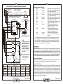
DIESEL ENGINE CHASSIS WIRING DIAGRAM
Fuse
+12 V Ignition (This supply
must be from a circuit with
no other loads such as relays
that might generate electrical
noise)
RPM Control
*
10,000 Ohm
10-Turn
Chassis Ground
(Battery Neg.)
* Optional
FORD SEIC WIRE COLOR CHART
F-Series Diesel
Function
PTO
2005 - 2007
6.0 L
Orange
2008 - 2010
6.4 L
2011 and later
6.7 L
E-Series Diesel
2005 - 2008
6.0 L
2009
6.0 L
Yellow/Green
Yellow/Green
Purple/Lt. Blue
Yellow/Green
PTO RPM
Orange/Yellow
Green
Green
Orange/Yellow
Green
PTO VREF
Orange/Red
White/Brown
White/Brown
Orange/Red
White/Brown
ETM51 OM-54H