1
SIMATIC RF200
1
___________________
Introduction
2
___________________
Safety notes
SIMATIC Ident
RFID systems
SIMATIC RF200
3
___________________
System overview
4
___________________
RF200 system planning
5
___________________
Readers
6
___________________
Antennas
System Manual
7
___________________
Transponder
8
___________________
Accessories
9
___________________
System integration
10
___________________
System diagnostics
A
___________________
Appendix
09/2013
J31069-D0227-U001-A8-7618
Legal information
Warning notice system
This manual contains notices you have to observe in order to ensure your personal safety, as well as to prevent
damage to property. The notices referring to your personal safety are highlighted in the manual by a safety alert
symbol, notices referring only to property damage have no safety alert symbol. These notices shown below are
graded according to the degree of danger.
DANGER
indicates that death or severe personal injury will result if proper precautions are not taken.
WARNING
indicates that death or severe personal injury may result if proper precautions are not taken.
CAUTION
indicates that minor personal injury can result if proper precautions are not taken.
NOTICE
indicates that property damage can result if proper precautions are not taken.
If more than one degree of danger is present, the warning notice representing the highest degree of danger will
be used. A notice warning of injury to persons with a safety alert symbol may also include a warning relating to
property damage.
Qualified Personnel
The product/system described in this documentation may be operated only by personnel qualified for the specific
task in accordance with the relevant documentation, in particular its warning notices and safety instructions.
Qualified personnel are those who, based on their training and experience, are capable of identifying risks and
avoiding potential hazards when working with these products/systems.
Proper use of Siemens products
Note the following:
WARNING
Siemens products may only be used for the applications described in the catalog and in the relevant technical
documentation. If products and components from other manufacturers are used, these must be recommended
or approved by Siemens. Proper transport, storage, installation, assembly, commissioning, operation and
maintenance are required to ensure that the products operate safely and without any problems. The permissible
ambient conditions must be complied with. The information in the relevant documentation must be observed.
Trademarks
All names identified by ® are registered trademarks of Siemens AG. The remaining trademarks in this publication
may be trademarks whose use by third parties for their own purposes could violate the rights of the owner.
Disclaimer of Liability
We have reviewed the contents of this publication to ensure consistency with the hardware and software
described. Since variance cannot be precluded entirely, we cannot guarantee full consistency. However, the
information in this publication is reviewed regularly and any necessary corrections are included in subsequent
editions.
Siemens AG
Industry Sector
Postfach 48 48
90026 NÜRNBERG
GERMANY
Order number: J31069-D0227-U001
Ⓟ 10/2013 Technical data subject to change
Copyright © Siemens AG 2010 - 2013.
All rights reserved
Table of contents
1
Introduction ........................................................................................................................................... 13
2
Safety notes .......................................................................................................................................... 15
3
System overview ................................................................................................................................... 17
4
5
3.1
RFID components and their function ...........................................................................................18
3.2
Overview of transponders ............................................................................................................20
RF200 system planning......................................................................................................................... 23
4.1
4.1.1
4.1.2
4.1.3
4.1.4
4.1.5
4.1.6
4.1.7
4.1.8
Fundamentals of application planning .........................................................................................23
Selection criteria for SIMATIC RF200 components .....................................................................23
Transmission window and read/write distance ............................................................................23
Width of the transmission window................................................................................................26
Permissible directions of motion of the transponder ....................................................................27
Operation in static and dynamic mode ........................................................................................27
Dwell time of the transponder ......................................................................................................28
Communication between communication module, reader and transponder ...............................29
Impact of secondary fields ...........................................................................................................32
4.2
4.2.1
4.2.2
Field data of transponders and readers .......................................................................................35
Field data .....................................................................................................................................35
Minimum clearances ....................................................................................................................40
4.3
4.3.1
4.3.2
4.3.3
4.3.4
4.3.4.1
4.3.4.2
4.3.4.3
4.3.4.4
4.3.4.5
4.3.4.6
4.3.5
4.3.5.1
4.3.5.2
4.3.5.3
Installation guidelines ...................................................................................................................42
Overview ......................................................................................................................................42
Reduction of interference due to metal ........................................................................................43
Effects of metal on different transponders and readers ...............................................................45
Impact of metal on the transmission window ...............................................................................46
RF210R ........................................................................................................................................47
RF220R ........................................................................................................................................50
RF240R ........................................................................................................................................52
RF250R ........................................................................................................................................55
RF260R ........................................................................................................................................60
RF290R ........................................................................................................................................62
Installation and connection of 2 to 6 antennas with one reader ..................................................66
Installation options with the antenna splitter (2-4 antennas) .......................................................67
Antenna installation ......................................................................................................................70
Installation options with the antenna multiplexer (2-6 antennas) .................................................74
4.4
Further information .......................................................................................................................74
Readers ................................................................................................................................................ 75
5.1
5.1.1
5.1.2
5.1.3
5.1.4
5.1.5
SIMATIC RF210R ........................................................................................................................76
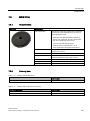
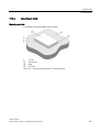
Features .......................................................................................................................................76
RF210R ordering data .................................................................................................................76
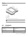
Pin assignment RF210R with RS422 interface ............................................................................77
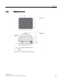
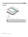
Display elements of the RF210R reader ......................................................................................77
Minimum distance between RF210R readers ..............................................................................78
SIMATIC RF200
System Manual, 09/2013, J31069-D0227-U001-A8-7618
5
Table of contents
5.1.6
5.1.7
5.1.8
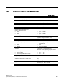
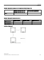
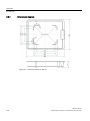
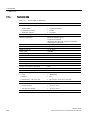
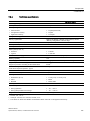
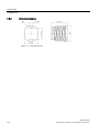
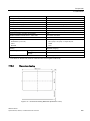
Technical specifications of the RF210R reader .......................................................................... 79
Approvals .................................................................................................................................... 80
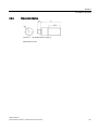
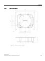
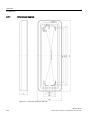
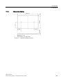
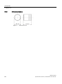
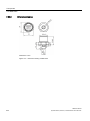
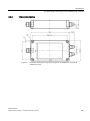
Dimension drawing ...................................................................................................................... 81
5.2
5.2.1
5.2.2
5.2.3
5.2.4
5.2.5
5.2.6
5.2.7
5.2.8
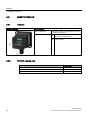
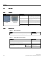
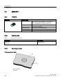
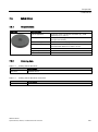
SIMATIC RF220R ....................................................................................................................... 82
Features ...................................................................................................................................... 82
RF220R ordering data................................................................................................................. 82
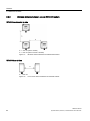
RF220R pin assignment with RS422 interface ........................................................................... 83
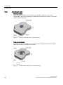
Display elements of the RF220R reader ..................................................................................... 83
Minimum distance between RF220R readers ............................................................................. 84
Technical specifications of the RF220R reader .......................................................................... 85
Approvals .................................................................................................................................... 86
Dimension drawing ...................................................................................................................... 86
5.3
5.3.1
5.3.2
5.3.3
5.3.4
5.3.5
5.3.6
5.3.7
5.3.8
SIMATIC RF240R ....................................................................................................................... 88
Features ...................................................................................................................................... 88
RF240R ordering data................................................................................................................. 88
Pin assignment RF240R ............................................................................................................. 89
Display elements of the RF240R reader ..................................................................................... 89
Minimum distance between several RF240R readers ................................................................ 90
Technical specifications of the RF240R reader .......................................................................... 91
Approvals .................................................................................................................................... 92
Dimension drawing ...................................................................................................................... 92
5.4
5.4.1
5.4.2
5.4.3
5.4.4
5.4.5
5.4.6
5.4.7
SIMATIC RF250R ....................................................................................................................... 94
Features ...................................................................................................................................... 94
Ordering data RF250R ................................................................................................................ 94
Pin assignment RF250R ............................................................................................................. 95
Display elements of the RF250R reader ..................................................................................... 95
Technical specifications of the RF250R reader .......................................................................... 96
Approvals .................................................................................................................................... 97
Dimension drawing ...................................................................................................................... 97
5.5
5.5.1
5.5.2
5.5.3
5.5.4
5.5.5
5.5.6
5.5.7
5.5.8
SIMATIC RF260R ....................................................................................................................... 99
Features ...................................................................................................................................... 99
Ordering data for RF260R........................................................................................................... 99
Pin assignment RF260R ........................................................................................................... 100
Display elements of the RF260R reader ................................................................................... 100
Minimum distance between several RF260R ........................................................................... 101
Technical data of the RF260R reader ....................................................................................... 102
Approvals .................................................................................................................................. 103
Dimension drawing .................................................................................................................... 103
5.6
5.6.1
5.6.2
5.6.3
5.6.4
5.6.5
5.6.5.1
5.6.5.2
5.6.5.3
5.6.6
5.6.7
5.6.8
SIMATIC RF290R ..................................................................................................................... 105
Features .................................................................................................................................... 105
Ordering data RF290R .............................................................................................................. 105
Pin assignment RF290R ........................................................................................................... 107
Display elements of the RF290R reader ................................................................................... 109
Installing the RF290R reader .................................................................................................... 110
Wall mounting ........................................................................................................................... 110
Installing on the S7-300 standard rail ....................................................................................... 111
Installation on a DIN rail ............................................................................................................ 111
Technical specifications of the RF290R reader ........................................................................ 113
Approvals .................................................................................................................................. 114
Note on the use of the RF290R as a replacement for SLG D10 / SLG D10S .......................... 115
SIMATIC RF200
6
System Manual, 09/2013, J31069-D0227-U001-A8-7618
Table of contents
5.6.9
6
Dimension drawing ....................................................................................................................116
Antennas ............................................................................................................................................ 117
6.1
6.1.1
6.1.2
6.1.3
6.1.4
6.1.5
6.1.6
6.1.7
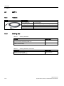
ANT 8 .........................................................................................................................................118
Features .....................................................................................................................................118
Ordering data .............................................................................................................................118
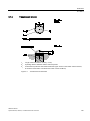
Transmission window .................................................................................................................119
Flush-mounted in metal .............................................................................................................120
Minimum spacing .......................................................................................................................120
Technical data ............................................................................................................................122
Dimension drawing ....................................................................................................................122
6.2
6.2.1
6.2.2
6.2.3
6.2.4
6.2.5
6.2.6
6.2.7
ANT 12 .......................................................................................................................................123
Features .....................................................................................................................................123
Ordering data .............................................................................................................................123
Transmission window .................................................................................................................124
Flush-mounted in metal .............................................................................................................125
Minimum spacing .......................................................................................................................125
Technical data ............................................................................................................................127
Dimension drawing ....................................................................................................................127
6.3
6.3.1
6.3.2
6.3.3
6.3.4
6.3.5
6.3.6
6.3.7
ANT 18 .......................................................................................................................................128
Features .....................................................................................................................................128
Ordering data .............................................................................................................................128
Transmission window .................................................................................................................129
Flush-mounted in metal .............................................................................................................130
Minimum spacing .......................................................................................................................130
Technical data ............................................................................................................................132
Dimension drawing ....................................................................................................................132
6.4
6.4.1
6.4.2
6.4.3
6.4.4
6.4.5
6.4.6
6.4.7
ANT 30 .......................................................................................................................................133
Features .....................................................................................................................................133
Ordering data .............................................................................................................................133
Transmission window .................................................................................................................134
Flush-mounted in metal .............................................................................................................135
Minimum spacing .......................................................................................................................135
Technical data ............................................................................................................................137
Dimension drawing ....................................................................................................................137
6.5
6.5.1
6.5.2
6.5.3
6.5.4
6.5.5
6.5.6
6.5.7
ANT D5 ......................................................................................................................................138
Features .....................................................................................................................................138
Ordering data .............................................................................................................................138
Transmission window .................................................................................................................139
Flush-mounted in metal .............................................................................................................140
Minimum spacing .......................................................................................................................140
Technical data ............................................................................................................................142
Dimension drawing ....................................................................................................................143
6.6
6.6.1
6.6.2
6.6.3
6.6.4
6.6.5
6.6.6
ANT D6 ......................................................................................................................................144
Features .....................................................................................................................................144
Ordering data .............................................................................................................................144
Transmission window .................................................................................................................145
Metal-free area ...........................................................................................................................146
Minimum spacing .......................................................................................................................146
Technical data ............................................................................................................................147
SIMATIC RF200
System Manual, 09/2013, J31069-D0227-U001-A8-7618
7
Table of contents
7
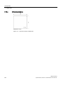
6.6.7
Dimensional diagram ................................................................................................................ 148
6.7
6.7.1
6.7.2
6.7.3
6.7.4
6.7.5
6.7.6
6.7.7
ANT D10.................................................................................................................................... 149
Features .................................................................................................................................... 149
Ordering data ............................................................................................................................ 149
Transmission window ................................................................................................................ 150
Metal-free area .......................................................................................................................... 151
Minimum spacing ...................................................................................................................... 152
Technical data ........................................................................................................................... 153
Dimensional diagram ................................................................................................................ 154
Transponder ........................................................................................................................................155
7.1
7.1.1
7.1.2
7.1.3
7.1.4
7.1.5
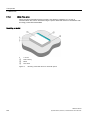
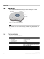
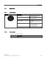
MDS D100 ................................................................................................................................. 155
Characteristics .......................................................................................................................... 155
Ordering data ............................................................................................................................ 155
Metal-free area .......................................................................................................................... 156
Technical data ........................................................................................................................... 158
Dimension drawing .................................................................................................................... 159
7.2
7.2.1
7.2.2
7.2.3
7.2.4
7.2.5
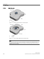
MDS D117 ................................................................................................................................. 160
Features .................................................................................................................................... 160
Ordering data ............................................................................................................................ 160
Mounting in metal ...................................................................................................................... 160
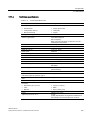
Technical specifications ............................................................................................................ 161
Dimension drawing .................................................................................................................... 162
7.3
7.3.1
7.3.2
7.3.3
7.3.4
7.3.5
7.3.6
MDS D124 ................................................................................................................................. 163
Characteristics .......................................................................................................................... 163
Ordering data ............................................................................................................................ 163
Mounting on metal ..................................................................................................................... 164
Technical specifications ............................................................................................................ 165
Use of the MDS D124 in hazardous area ................................................................................. 166
Dimension drawing .................................................................................................................... 168
7.4
7.4.1
7.4.2
7.4.3
7.4.4
MDS D126 ................................................................................................................................. 168
Characteristics .......................................................................................................................... 168
Ordering data ............................................................................................................................ 168
Technical specifications ............................................................................................................ 169
Dimension drawing .................................................................................................................... 170
7.5
7.5.1
7.5.2
7.5.3
7.5.4
7.5.5
MDS D127 ................................................................................................................................. 171
Features .................................................................................................................................... 171
Ordering data ............................................................................................................................ 171
Mounting in metal ...................................................................................................................... 172
Technical specifications ............................................................................................................ 173
Dimension drawing .................................................................................................................... 174
7.6
7.6.1
7.6.2
7.6.3
7.6.4
7.6.5
7.6.6
MDS D139 ................................................................................................................................. 175
Characteristics .......................................................................................................................... 175
Ordering data ............................................................................................................................ 175
Metal-free area .......................................................................................................................... 176
Technical specifications ............................................................................................................ 176
Use of the MDS D139 in hazardous areas ............................................................................... 178
Dimension drawings .................................................................................................................. 180
SIMATIC RF200
8
System Manual, 09/2013, J31069-D0227-U001-A8-7618
Table of contents
7.7
7.7.1
7.7.2
7.7.3
7.7.4
7.7.5
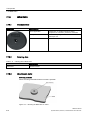
MDS D160..................................................................................................................................182
Characteristics ...........................................................................................................................182
Ordering data .............................................................................................................................182
Mounting on metal .....................................................................................................................183
Technical specifications .............................................................................................................183
Dimension drawings ...................................................................................................................185
7.8
7.8.1
7.8.2
7.8.3
7.8.4
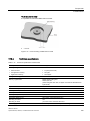
MDS D165..................................................................................................................................186
Features .....................................................................................................................................186
Ordering data .............................................................................................................................186
Technical data ............................................................................................................................187
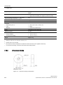
Dimension drawing ....................................................................................................................188
7.9
7.9.1
7.9.2
7.9.3
7.9.4
7.9.5
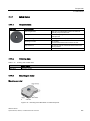
MDS D200..................................................................................................................................188
Features .....................................................................................................................................188
Ordering data .............................................................................................................................188
Mounting on metal .....................................................................................................................189
Technical data ............................................................................................................................190
Dimension drawing ....................................................................................................................191
7.10
7.10.1
7.10.2
7.10.3
7.10.4
MDS D261..................................................................................................................................192
Features .....................................................................................................................................192
Ordering data .............................................................................................................................192
Technical data ............................................................................................................................193
Dimension drawing ....................................................................................................................194
7.11
7.11.1
7.11.2
7.11.3
7.11.4
7.11.5
MDS D324..................................................................................................................................195
Characteristics ...........................................................................................................................195
Ordering data .............................................................................................................................195
Metal-free area ...........................................................................................................................196
Technical specifications .............................................................................................................197
Dimension drawing ....................................................................................................................198
7.12
7.12.1
7.12.2
7.12.3
7.12.4
7.12.5
7.12.6
7.12.7
MDS D339..................................................................................................................................199
Characteristics ...........................................................................................................................199
Ordering data .............................................................................................................................199
Mounting on metal .....................................................................................................................200
Mounting in metal .......................................................................................................................201
Technical specifications .............................................................................................................201
Use of the MDS D339 in hazardous areas ................................................................................202
Dimensional drawing ..................................................................................................................204
7.13
7.13.1
7.13.2
7.13.3
7.13.4
7.13.5
MDS D400..................................................................................................................................206
Features .....................................................................................................................................206
Ordering data .............................................................................................................................206
Mounting on metal .....................................................................................................................207
Technical specifications .............................................................................................................208
Dimension drawing ....................................................................................................................209
7.14
7.14.1
7.14.2
7.14.3
7.14.4
7.14.5
MDS D421..................................................................................................................................210
Characteristics ...........................................................................................................................210
Ordering data .............................................................................................................................210
Mounting on metal .....................................................................................................................211
Technical specifications .............................................................................................................213
Dimension drawing ....................................................................................................................214
SIMATIC RF200
System Manual, 09/2013, J31069-D0227-U001-A8-7618
9
Table of contents
8
7.15
7.15.1
7.15.2
7.15.3
7.15.4
7.15.5
MDS D422 ................................................................................................................................. 215
Characteristics .......................................................................................................................... 215
Ordering data ............................................................................................................................ 215
Mounting on metal ..................................................................................................................... 215
Technical specifications ............................................................................................................ 216
Dimension drawing .................................................................................................................... 217
7.16
7.16.1
7.16.2
7.16.3
7.16.4
7.16.5
MDS D423 ................................................................................................................................. 218
Characteristics .......................................................................................................................... 218
Ordering data ............................................................................................................................ 218
Mounting on metal ..................................................................................................................... 218
Technical specifications ............................................................................................................ 219
Dimensional drawing ................................................................................................................. 220
7.17
7.17.1
7.17.2
7.17.3
7.17.4
7.17.5
MDS D424 ................................................................................................................................. 221
Characteristics .......................................................................................................................... 221
Ordering data ............................................................................................................................ 221
Mounting on metal ..................................................................................................................... 221
Technical specifications ............................................................................................................ 222
Dimension drawing .................................................................................................................... 223
7.18
7.18.1
7.18.2
7.18.3
7.18.4
7.18.5
MDS D425 ................................................................................................................................. 224
Characteristics .......................................................................................................................... 224
Ordering data ............................................................................................................................ 224
Application example of MDS D425 ........................................................................................... 225
Technical specifications ............................................................................................................ 225
Dimension drawing .................................................................................................................... 227
7.19
7.19.1
7.19.2
7.19.3
7.19.4
MDS D426 ................................................................................................................................. 228
Characteristics .......................................................................................................................... 228
Ordering data ............................................................................................................................ 228
Technical specifications ............................................................................................................ 228
Dimension drawing .................................................................................................................... 230
7.20
7.20.1
7.20.2
7.20.3
7.20.4
7.20.5
MDS D428 ................................................................................................................................. 231
Characteristics .......................................................................................................................... 231
Ordering data ............................................................................................................................ 231
Application example of MDS D428 ........................................................................................... 232
Technical specifications ............................................................................................................ 232
Dimension drawing .................................................................................................................... 234
7.21
7.21.1
7.21.2
7.21.3
7.21.4
7.21.5
MDS D460 ................................................................................................................................. 235
Characteristics .......................................................................................................................... 235
Ordering data ............................................................................................................................ 235
Mounting on metal ..................................................................................................................... 236
Technical specifications ............................................................................................................ 237
Dimension drawings .................................................................................................................. 238
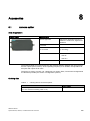
Accessories .........................................................................................................................................239
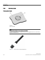
8.1
Antenna splitter ......................................................................................................................... 239
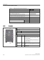
8.2
8.2.1
8.2.2
8.2.3
8.2.4
Antenna multiplexer SIMATIC RF260X .................................................................................... 241
Characteristics .......................................................................................................................... 241
Ordering data ............................................................................................................................ 241
Description ................................................................................................................................ 242
Principle of operation ................................................................................................................ 243
SIMATIC RF200
10
System Manual, 09/2013, J31069-D0227-U001-A8-7618
Table of contents
8.2.5
8.2.6
8.2.7
8.2.8
8.2.9
8.2.10
Connectors .................................................................................................................................243
Configuration ..............................................................................................................................244
Parameterization ........................................................................................................................245
RF260X commands ...................................................................................................................246
Technical specifications .............................................................................................................247
Dimensional drawing ..................................................................................................................248
8.3
8.3.1
8.3.2
8.3.3
8.3.4
8.3.5
8.3.6
8.3.7
8.3.8
8.3.9
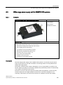
Wide-range power supply unit for SIMATIC RF systems ..........................................................249
Features .....................................................................................................................................249
Scope of supply..........................................................................................................................250
Ordering data .............................................................................................................................250
Safety Information ......................................................................................................................250
Connecting .................................................................................................................................252
Technical specifications .............................................................................................................252
Pin assignment of DC outputs and mains connection ...............................................................254
Dimension drawing ....................................................................................................................255
Certificates and approvals .........................................................................................................256
9
System integration .............................................................................................................................. 257
10
System diagnostics ............................................................................................................................. 259
A
10.1
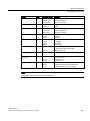
Error codes of the RF200 readers .............................................................................................259
10.2
10.2.1
10.2.2
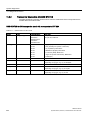
Diagnostic functions ...................................................................................................................260
Reader diagnostics with SLG STATUS .....................................................................................260
Transponder diagnostics with MDS STATUS ............................................................................262
Appendix............................................................................................................................................. 263
A.1
Certificates and approvals .........................................................................................................263
A.2
A.2.1
A.2.2
A.2.3
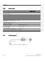
Connecting cable .......................................................................................................................265
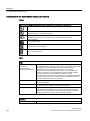
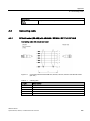
RF2xxR reader (RS-422) with ASM 456 / RF160C / RF170C / RF180C ..................................265
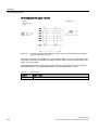
Reader RF2xxR (RS-422) with ASM 475 ..................................................................................267
Reader RF240R/RF260R/RF290R (RS232) with PC ................................................................268
A.3
Ordering data .............................................................................................................................269
A.4
Service & Support ......................................................................................................................278
Glossary ............................................................................................................................................. 281
Index................................................................................................................................................... 287
SIMATIC RF200
System Manual, 09/2013, J31069-D0227-U001-A8-7618
11
Table of contents
SIMATIC RF200
12
System Manual, 09/2013, J31069-D0227-U001-A8-7618
Introduction
1
Introduction
SIMATIC RF200 is a compact RFID system in the SIMATIC RF product family. The product
range comprises cost-efficient RF readers that are ideal for use in small assembly lines or in
intralogistics. SIMATIC RF200 RFID readers only support the RFID standard ISO 15693 and
are therefore ideal for operation with the extensive range of MOBY D transponders.
All readers of the RF200 product family are available with an RS-422 interface and 3964R
transmission protocol (6GT2821-xAC10). These readers are designed for operation in
conjunction with communications modules. To operate with third-party controllers (without
communications modules), RF200 reader variants are available with an RS-232 interface
(RF240R/RF250R/RF260R/RF290R). Depending on the reader type and order number,
communication is with the 3964R transmission protocol or with simple ASCII communication.
Readers with an internal antenna have a particularly compact design
(RF210R/RF220R/RF240R/RF260R). RF250R and RF290R are designed for operation with
external antennas either to achieve longer distances or larger field sizes (RF290R with ANT
D5/D6/D10) or to allow installation where there is very little space (RF250R with ANT
8/12/18/30).
Scope of validity of this document
This documentation is valid for all variants of the SIMATIC RF200 system and describes the
devices shipped as of September 2013.
Registered trademarks
SIMATIC ® is a registered trademark of the Siemens AG.
Further information
You will find more detailed information in MOBY D System Manual
(http://support.automation.siemens.com/WW/view/en/13628689/0/en), Function Manual FB
45 (http://support.automation.siemens.com/WW/view/en/21738808) or in RF300 system
manual (http://support.automation.siemens.com/WW/view/en/21738946).
SIMATIC RF200
System Manual, 09/2013, J31069-D0227-U001-A8-7618
13
Introduction
History
The following issues of the SIMATIC RF200 system manual have been published:
Output
Note
03/2011
First edition
05/2011
Expansion of the documentation with the addition of the device variant RF260R with
RS-232 interface
09/2011
Expansion of the documentation with the device variant RF240R
03/2013
Expansion of the documentation with the device variant RF290R
09/2013
Expansion of the documentation by the following:
•
the device variant RF250R
•
the device variants RF240R and RF260R with ASCII interface
•
Antennas ANT 8, ANT 12, ANT 18 and ANT 30
•
Transponders
SIMATIC RF200
14
System Manual, 09/2013, J31069-D0227-U001-A8-7618
2
Safety notes
SIMATIC RFID products comply with the salient safety specifications to IEC, VDE, EN, UL
and CSA. If you have questions about the validity of the installation in the planned
environment, please contact your service representative.
NOTICE
Alterations to the devices are not permitted.
Failure to observe this requirement shall constitute a revocation of the radio equipment
approval, CE approval and manufacturer's warranty.
Repairs
Repairs may only be carried out by authorized qualified personnel.
WARNING
Unauthorized opening of and improper repairs to the device may result in substantial
damage to equipment or risk of personal injury to the user.
System expansion
Only install system expansion devices designed for this device. If you install other upgrades,
you may damage the system or violate the safety requirements and regulations for radio
frequency interference suppression. Contact your technical support team or your sales outlet
to find out which system upgrades are suitable for installation.
NOTICE
If you cause system defects by installing or exchanging system expansion devices, the
warranty becomes void.
SIMATIC RF200
System Manual, 09/2013, J31069-D0227-U001-A8-7618
15
Safety notes
SIMATIC RF200
16
System Manual, 09/2013, J31069-D0227-U001-A8-7618
System overview
3
SIMATIC RF200 is an inductive identification system that is compatible with the ISO 15693
standard and was specially designed for use in industrial production for the control and
optimization of material flows.
In contrast to SIMATIC RF300, SIMATIC RF200 is intended for RFID applications where
performance requirements are not very high, for example with regard to data volume,
transfer rate or diagnostics options. SIMATIC RF200 is characterized by particularly
favorable prices.
SIMATIC RF200
System Manual, 09/2013, J31069-D0227-U001-A8-7618
17
System overview
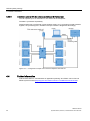
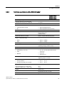
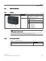
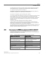
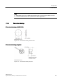
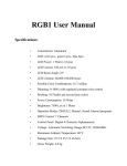
3.1 RFID components and their function
3.1
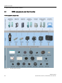
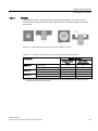
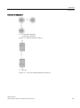
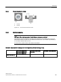
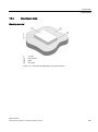
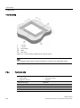
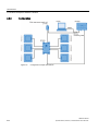
RFID components and their function
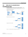
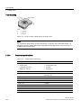
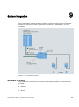
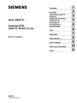
RF200 system components
Figure 3-1
RF200 system overview
SIMATIC RF200
18
System Manual, 09/2013, J31069-D0227-U001-A8-7618
System overview
3.1 RFID components and their function
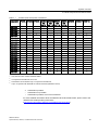
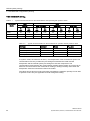
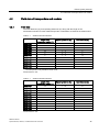
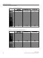
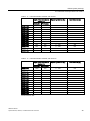
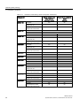
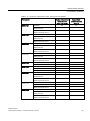
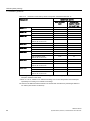
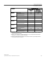
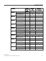
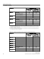
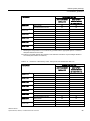
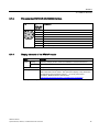
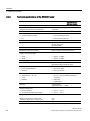
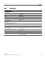
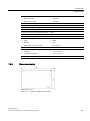
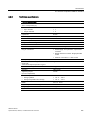
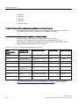
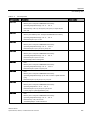
Table 3- 1
Possible reader-transponder combinations
Transponder
RF210R
RF220R
RF240R RF250R RF250R RF250R RF250R
with
with
with
with
ANT 8 ANT 12 ANT 18 ANT 30
RF260R
RF290R 3)
RF310M
MDS D100
--
○
✓
--
--
--
○
✓
✓
✓
MDS D117
○
--
--
✓
✓
--
--
--
--
✓ 5)
MDS D124
✓
✓
✓
--
--
✓
✓
✓
✓
✓
MDS D126
--
✓
✓
--
--
--
✓
✓
✓
✓
MDS D127
✓
--
--
✓
✓
--
--
--
--
✓ 5)
MDS D139 1)
--
○
○
--
--
--
○
✓
✓
✓
MDS D160
✓
✓
✓
--
✓
✓
✓
✓
✓
✓
MDS D165
--
○
✓
--
--
--
○
✓
✓
✓
MDS D200
--
○
✓
--
--
--
○
✓
✓
✓
MDS D261
--
○
✓
--
--
--
○
✓
✓
✓
MDS D324
✓
✓
✓
--
○
✓
✓
✓
✓
✓
MDS D339
--
○
○
--
--
--
○
✓
✓
✓
MDS D400
--
--
✓
--
--
--
○
✓
✓
✓
MDS D421
✓
○
--
✓
✓
✓
--
--
--
✓ 5)
MDS D422
✓
✓
✓
--
✓
✓
✓
--
--
✓ 5)
MDS D423
✓
✓
✓
--
--
✓
✓
✓
--
✓
MDS D424
✓
✓
✓
--
--
✓
✓
✓
✓
✓
MDS D425
✓
✓
✓
--
✓
✓
✓
--
--
✓
MDS D426
--
✓
✓
--
--
--
✓
✓
✓
✓
MDS D428
✓
✓
✓
--
✓
✓
✓
✓
--
✓
MDS D460
✓
✓
✓
--
✓
✓
✓
✓
○ / ✓ 4)
✓
2)
1)
Only with the order number 6GT2600-0AA10
2)
Only with the order number 6GT2600-0AB10
3)
in conjunction with ANT D5, D6 or D10
4)
Combination recommended only in conjunction with ANT D5.
5)
only in conjunction with RF310M for external antennas (6GT2803-1AC10)
✓ Combination possible
--
Combination not possible
○
Combination possible, but not recommended
For more detailed information about the SIMATIC RF310M mobile reader, please refer to the
"SIMATIC RF310M Operating Instructions
(http://support.automation.siemens.com/WW/view/en/51812642)".
SIMATIC RF200
System Manual, 09/2013, J31069-D0227-U001-A8-7618
19
System overview
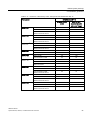
3.2 Overview of transponders
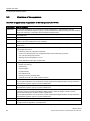
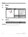
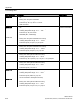
3.2
Overview of transponders
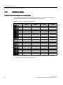
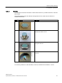
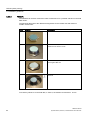
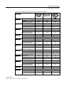
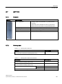
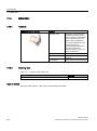
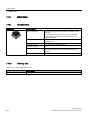
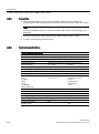
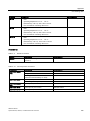
Overview of typical areas of application of ISO transponders for RF200
Transponder
Area of application
MDS D100
From simple identification such as electronic barcode replacement or supplementation, through
warehouse and distribution logistics, right up to product identification. With this transponder, the maximum
ranges are achieved in combination with the SIMATIC RF260R reader.
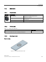
MDS D117
Very compact data carrier that can be cemented into areas where precise positioning is necessary. e.g.
tool identification.
MDS D124
Application areas in factory automation (e.g. small paintshops to 180°C).
MDS D126
Compact and rugged ISO transponder; suitable for identification of transport units in production-related
logistics; can also be deployed in harsh conditions.
MDS D127
Very compact data carrier that can be screwed into areas where precise positioning is necessary. e.g. tool
identification.
MDS D139 1)
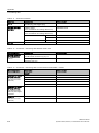
Applications in production automation with high temperature demands (up to +220 °C).
Typical application areas:
MDS D160
MDS D165
2)
•
Paintshops and their preparatory treatments
•
Primer coat, electrolytic dip area, cataphoresis with the associated drying furnaces
•
Top coat area with drying furnaces
•
Washing areas at temperatures > 85 °C
•
Other applications with higher temperatures
Typical applications are, for example:
•
Rented work clothing
•
Hotel laundry
•
Surgical textiles
•
Hospital clothing
•
Dirt collection mats
•
Clothing for nursing homes/hostels
•
Assembly lines with very small workpiece holders
Smart label (self-adhesive label)
From simple identification such as electronic barcode replacement/supplementation, through warehouse
and distribution logistics, right up to product identification
MDS D200
From simple identification such as electronic barcode replacement/supplementation, through warehouse
and distribution logistics, right up to product identification.
MDS D261
Smart label (self-adhesive label)
The design of the transponder (self-adhesive label) permits a variety of designs in order to ensure
optimum dimensioning for the widest variety of applications.
From simple identification such as electronic barcode replacement/supplementation, through warehouse
and distribution logistics, right up to product identification.
MDS D324
Production and distribution logistics as well as in assembly and production lines
MDS D339
Applications in production automation with high temperature demands (up to +220 °C).
For typical areas of application, see "MDS D139".
SIMATIC RF200
20
System Manual, 09/2013, J31069-D0227-U001-A8-7618
System overview
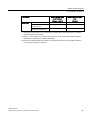
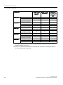
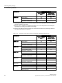
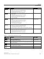
3.2 Overview of transponders
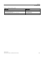
Transponder
Area of application
MDS D400
Simple identification such as electronic barcode replacement/supplements, from warehouse and
distribution logistics right through to product identification.
MDS D421
The MDS D421 is designed for tool coding according to DIN 69873.
It can be used wherever small data carriers and exact positioning are required, e.g. tool identification,
workpiece holders
MDS D422
Identification of metallic workpiece holders, workpieces or containers
MDS D423
Identification of metallic workpiece holders, workpieces or containers, production automation
MDS D424
Production and distribution logistics as well as in assembly and production lines
MDS D425
Compact and rugged ISO transponder; suitable for screw mounting.
Use in assembly and production lines in the powertrain sector; ideal for mounting on motors, gearboxes,
and workpiece holders
MDS D426
Compact and rugged ISO transponder; suitable for identification of transport units in production-related
logistics; can also be deployed in harsh conditions
MDS D428
Compact and rugged ISO transponder; suitable for screw mounting
Use in assembly and production lines in the powertrain sector
MDS D460
Assembly lines with very small workpiece holders
1)
Only with the MLFB 6GT2600-0AA10
2)
Only with the MLFB 6GT2600-0AB10
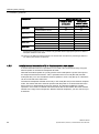
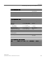
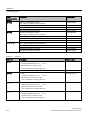
Overview of the memory sizes of the ISO transponders for RF200
Transponder
Memory size
MDS D1xx
112 bytes of EEPROM
MDS D2xx
256 bytes of EEPROM
MDS D3xx
992 bytes of EEPROM
MDS D4xx
2000 bytes FRAM
See also
MOBY D System Manual
(http://support.automation.siemens.com/WW/view/en/13628689/0/en)
SIMATIC RF200
System Manual, 09/2013, J31069-D0227-U001-A8-7618
21
System overview
3.2 Overview of transponders
SIMATIC RF200
22
System Manual, 09/2013, J31069-D0227-U001-A8-7618
RF200 system planning
4.1
Fundamentals of application planning
4.1.1
Selection criteria for SIMATIC RF200 components
4
Assess your application according to the following criteria, in order to choose the right
SIMATIC RF200 components:
● Static or dynamic data transfer
● Data volume to be transferred
● Speed in case of dynamic transfer
● Ambient conditions such as relative humidity, temperature, chemical impacts, etc.
4.1.2
Transmission window and read/write distance
The reader generates an inductive alternating field. The field is strongest close to the reader;
however, a read/write distance of "zero" between reader and transponder is not
recommended.
The strength of the field decreases in proportion to the distance from the reader. The
distribution of the field depends on the structure and geometry of the antennas in the reader
and transponder
A prerequisite for the function of the transponder is a minimum field strength at the
transponder, which is still barely achieved at distance Sg from the reader.
SIMATIC RF200
System Manual, 09/2013, J31069-D0227-U001-A8-7618
23
RF200 system planning
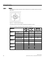
4.1 Fundamentals of application planning
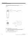
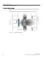
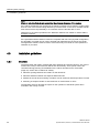
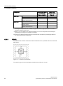
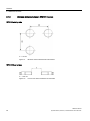
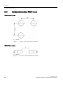
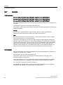
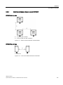
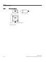
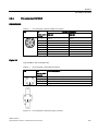
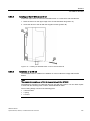
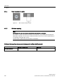
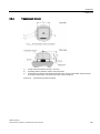
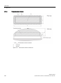
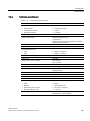
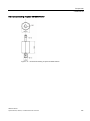
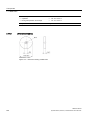
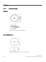
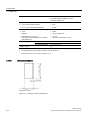
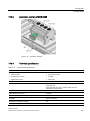
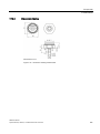
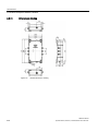
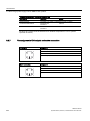
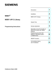
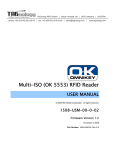
The picture below shows the transmission window of the SIMATIC RF210R and
SIMATIC RF220R readers between transponder and reader:
Sa
Operating distance between transponder and reader
Sg
Limit distance (maximum clear distance between upper surface of the reader and the
transponder, at which the transmission can still function under normal conditions)
L
Diameter of a transmission window
SP
Intersection of the axes of symmetry of the transponder
Figure 4-1
RF210R/RF220R transmission window
SIMATIC RF200
24
System Manual, 09/2013, J31069-D0227-U001-A8-7618
RF200 system planning
4.1 Fundamentals of application planning
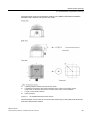
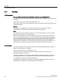
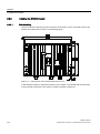
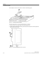
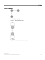
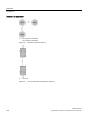
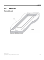
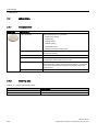
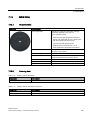
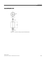
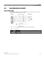
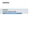
The figure below shows the transmission window of the SIMATIC RF240R and SIMATIC
RF260R readers between transponder and reader:
Sa
Operating distance between transponder and reader
Sg
Limit distance (maximum clear distance between upper surface of the reader and the
transponder, at which the transmission can still function under normal conditions)
L
Length of a transmission window
M
Field centerpoint
Figure 4-2
RF240R/RF260R transmission window
The transponder can be used as soon as the intersection (SP) of the transponder enters the
area of the transmission window.
SIMATIC RF200
System Manual, 09/2013, J31069-D0227-U001-A8-7618
25
RF200 system planning
4.1 Fundamentals of application planning
From the diagrams above, it can also be seen that operation is possible within the area
between Sa and Sg. The active operating area reduces as the distance increases, and
shrinks to a single point at distance Sg. Only static mode should thus be used in the area
between Sa and Sg.
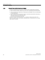
4.1.3
Width of the transmission window
Determining the width of the transmission window
The following approximation formula can be used for practical applications:
B:
Width of the transmission window
L:
Length of the transmission window
Tracking tolerances
The width of the transmission window (B) is particularly important for the mechanical tracking
tolerance. The formula for the dwell time is valid without restriction when B is observed.
SIMATIC RF200
26
System Manual, 09/2013, J31069-D0227-U001-A8-7618
RF200 system planning
4.1 Fundamentals of application planning
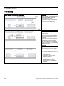
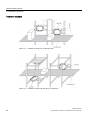
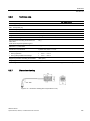
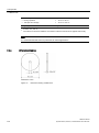
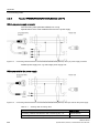
4.1.4
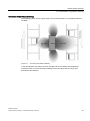
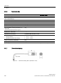
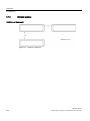
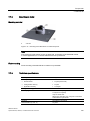
Permissible directions of motion of the transponder
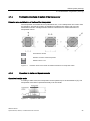
Detection area and direction of motion of the transponder
The transponder and reader have no polarization axis, i.e. the transponder can come in from
any direction, assume any position as parallel as possible to the reader, and cross the
transmission window. The figure below shows the active area for various directions of
transponder motion:
Transmission window
Direction of motion of the transponder
Detection area L x W
Figure 4-3
4.1.5
Detection areas of the reader for different directions of transponder motion
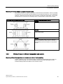
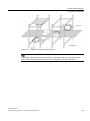
Operation in static and dynamic mode
Operation in static mode
If working in static mode, the transponder can be operated up to the limit distance (Sg). The
transponder must then be positioned exactly over the reader:
Figure 4-4
Operation in static mode
SIMATIC RF200
System Manual, 09/2013, J31069-D0227-U001-A8-7618
27
RF200 system planning
4.1 Fundamentals of application planning
Note
Note that in a metallic environment the values for the limit distance are reduced.
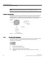
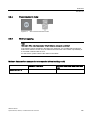
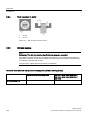
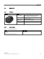
Operation in dynamic mode
When working in dynamic mode, the transponder moves past the reader. The transponder
can be used as soon as the intersection (SP) of the transponder enters the circle of the
transmission window. In dynamic mode, the operating distance (Sa) is of primary importance.
[Operating distances, see Chapter Field data of transponders and readers (Page 35)]
Figure 4-5
4.1.6
Operation in dynamic mode
Dwell time of the transponder
The dwell time is the time in which the transponder remains within the transmission window
of a reader. The reader can exchange data with the transponder during this time.
The dwell time is calculated thus:
tV:
Dwell time of the transponder
L:
Length of the transmission window
vTag:
Speed of the transponder (tag) in dynamic mode
0,8:
Constant factor used to compensate for temperature impacts and production
tolerances
SIMATIC RF200
28
System Manual, 09/2013, J31069-D0227-U001-A8-7618
RF200 system planning
4.1 Fundamentals of application planning
The dwell time can be of any duration in static mode. The dwell time must be sufficiently long
to allow communication with the transponder.
The dwell time is defined by the system environment in dynamic mode. The volume of data
to be transferred must be matched to the dwell time or vice versa. In general:
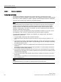
4.1.7
tV::
Dwell time of the data memory within the field of the reader
tK:
Communication time between transponder and communication module
Communication between communication module, reader and transponder
Communication between the communication module, reader and transponder takes place
asynchronously through the RS422 interface. Depending on the communication module
(ASM) used, transfer rates of 19200 baud, 57600 baud or 115200 baud can be selected.
Calculation of the communication time for interference-free transfer
The communication time for fault-free data transfer is calculated as follows:
If the transmission is interrupted briefly due to external interference, the reader automatically
continues the command.
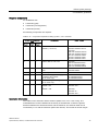
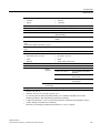
Calculation of the maximum amount of user data
The maximum amount of user data is calculated as follows:
tk:
Communication time between communication module, reader and transponder
tv:
Dwell time
n:
Amount of user data in bytes
nmax:
Max. amount of user data in bytes in dynamic mode
tbyte:
Transmission time for 1 byte
K:
Constant; the constant is an internal system time. This contains the time for power
buildup on the transponder and for command transfer
SIMATIC RF200
System Manual, 09/2013, J31069-D0227-U001-A8-7618
29
RF200 system planning
4.1 Fundamentals of application planning
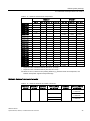
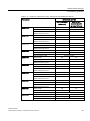
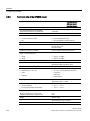
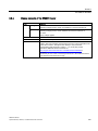
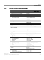
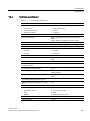
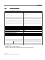
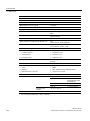
Time constants K and tbyte
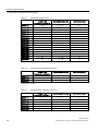
Table 4- 1
Typical communication time on the serial interface when operating with presence check
Transfer rate
[baud]
Read
Write
All MDS
MDS D1xx/D3xx
MDS D2xx
MDS D4xx
K
[ms]
tbyte
[ms]
K
[ms]
tbyte
[ms]
K
[ms]
tbyte
[ms]
K
[ms]
tbyte
[ms]
19200
35
1.08
41
2.66
50
8.1
35
1.08
57600
34
0.59
28
2.28
33
7.7
34
0.59
115200
26
0.56
26
2.17
31
7.6
26
0.56
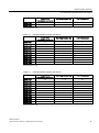
Table 4- 2
Typical command duration on the air interface for operation without presence check
TAG type
Command
K [ms]
Tbyte [ms]
All MDS
Read
20
0.55
EEPROM (MDS D1xx/D3xx)
Write
27
2.2
EEPROM (MDS D2xx)
Write
19
7.5
FRAM (MDS D4xx)
Write
27
0.55
In dynamic mode, the values for K and tbyte are independent of the transmission speed. The
communication time only includes the processing time between the reader and the
transponder and the internal system processing time of these components. The
communication times between the communication module and the reader do not have to be
taken into account because the command for reading or writing is already active when the
transponder enters the transmission field of the reader.
The values shown above must be used when calculating the maximum quantity of user data
in dynamic mode. They are applicable for both writing and reading.
SIMATIC RF200
30
System Manual, 09/2013, J31069-D0227-U001-A8-7618
RF200 system planning
4.1 Fundamentals of application planning
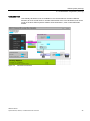
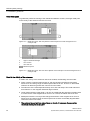
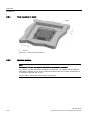
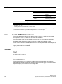
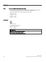
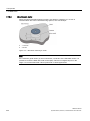
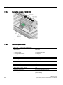
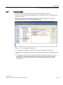
Calculation tool
User-friendly calculation tools are available for the communications modules ASM 456,
RF160C, RF170C and RF180C to calculate data transfer times. The calculation tools can be
found on the DVD "RFID Systems Software & Documentation", order number 6GT20802AA20.
Figure 4-6
Calculation tool interface
SIMATIC RF200
System Manual, 09/2013, J31069-D0227-U001-A8-7618
31
RF200 system planning
4.1 Fundamentals of application planning
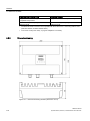
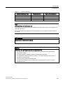
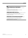
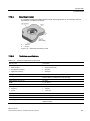
4.1.8
Impact of secondary fields
Secondary fields in the range from 0 mm to 30% of the limit distance (Sg) generally always
exist.
They should only be used during configuration in exceptional cases, however, since the
read/write distances are very limited. Exact details of the secondary field geometry cannot be
given, since these values depend heavily on the operating distance and the application.
When working in dynamic mode, remember that during the transition from the secondary
field to the main field the presence of the tag is lost temporarily. It is therefore advisable to
select a distance > 30% of Sg.
Figure 4-7
Gap in the field resulting from secondary fields
SIMATIC RF200
32
System Manual, 09/2013, J31069-D0227-U001-A8-7618
RF200 system planning
4.1 Fundamentals of application planning
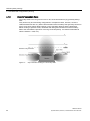
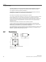
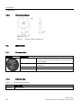
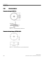
Secondary fields without shielding
The following graphic shows typical primary and secondary fields, if no shielding measures
are taken.
Figure 4-8
Secondary field without shielding
In this arrangement, the reader can also read tags via the secondary field. Shielding is
required in order to prevent unwanted reading via the secondary field, as shown and
described in the following.
SIMATIC RF200
System Manual, 09/2013, J31069-D0227-U001-A8-7618
33
RF200 system planning
4.1 Fundamentals of application planning
Secondary fields with shielding
The following graphic shows typical primary and secondary fields, with metal shielding this
time.
The metal shielding prevents the reader from detecting tags via the secondary field.
Figure 4-9
Secondary field with shielding
SIMATIC RF200
34
System Manual, 09/2013, J31069-D0227-U001-A8-7618
RF200 system planning
4.2 Field data of transponders and readers
4.2
Field data of transponders and readers
4.2.1
Field data
The limit distances (Sg) and operating distances (Sa) along with the length of the
transmission window for each reader-transponder combination are listed in the tables below.
Table 4- 3
SIMATIC RF210R field data
Length of the
transmission window (L)
Operating distance (Sa)
Limit distance (Sg)
25
1 ... 18
20
MDS D124
MDS D127
5
0 ... 2
2
MDS D160
20
1 ... 10
12
MDS D324
20
1 ... 8
9
MDS D421
5
0 ... 3
4
MDS D422
8
1 ... 9
10
MDS D423
20
2 ... 10
12
MDS D424
24
1 ... 16
18
MDS D425
12
1 ... 6
7
MDS D428
20
1 ... 10
11
MDS D460
8
1…8
9
Length of the
transmission window (L)
Operating distance (Sa)
Limit distance (Sg)
MDS D124
35
1 ... 28
31
MDS D126
45
2 ... 30
35
MDS D160
20
1 ... 20
22
MDS D324
30
2 ... 21
25
MDS D422
18
1 ... 12
14
MDS D423
30
2 ...24
28
MDS D424
30
2 ... 25
29
MDS D425
20
1 ... 11
13
MDS D426
40
2 ... 25
30
MDS D428
25
1 ... 18
21
MDS D460
25
1 ... 18
20
1)
1)
The transponder is only suitable for static mode.
All dimensions in mm.
Table 4- 4
SIMATIC RF220R field data
All dimensions in mm.
SIMATIC RF200
System Manual, 09/2013, J31069-D0227-U001-A8-7618
35
RF200 system planning
4.2 Field data of transponders and readers
Table 4- 5
SIMATIC RF240R field data
Length of the
transmission window (L)
Operating distance (Sa)
Limit distance (Sg)
MDS D100
100
2 ... 84
95
MDS D124
65
2 ... 53
60
MDS D126
80
2 ... 57
65
MDS D160
50
1 ... 33
37
MDS D165
105
2 ... 80
94
MDS D200
90
2 ... 69
78
MDS D261
70
2 ... 60
70
MDS D324
55
1 ... 36
40
MDS D400
95
2 ... 80
90
MDS D422
25
1 ... 12
15
MDS D423
40
2 ... 35
40
MDS D424
75
1 ... 47
53
MDS D425
30
1 ... 15
17
MDS D426
65
2 ... 45
55
MDS D428
50
1 ... 30
34
MDS D460
50
1 ... 30
34
Length of the
transmission window (L)
Operating distance (Sa)
Limit distance (Sg)
MDS D117
2
0 ... 2
3
MDS D127
3
0 ... 3
4
MDS D421
3
0 ... 3
4
Length of the
transmission window (L)
Operating distance (Sa)
Limit distance (Sg)
MDS D117
3
0 ... 3
4
MDS D127
4
0 ... 4
5
MDS D160
18
0 ... 12
17
MDS D421
10
0 ... 3
5
MDS D422
22
0 ... 7
10
MDS D425
12
0 ... 8
10
All dimensions in mm.
Table 4- 6
Field data SIMATIC RF250R, with ANT 8
All dimensions in mm.
Table 4- 7
Field data SIMATIC RF250R, with ANT 12
SIMATIC RF200
36
System Manual, 09/2013, J31069-D0227-U001-A8-7618
RF200 system planning
4.2 Field data of transponders and readers
Length of the
transmission window (L)
Operating distance (Sa)
Limit distance (Sg)
MDS D428
18
1 ... 10
15
MDS D460
16
1 ... 10
14
Length of the
transmission window (L)
Operating distance (Sa)
Limit distance (Sg)
MDS D124
26
2 ... 24
37
MDS D160
22
1 ... 18
26
MDS D324
30
1 ... 18
27
MDS D421
16
0 ... 3
4
MDS D422
24
1 ... 8
14
MDS D423
21
1 ... 15
18
MDS D424
26
1 ... 27
36
MDS D425
19
1 ... 11
16
MDS D428
19
1 ... 8
15
MDS D460
19
1 ... 17
21
Length of the
transmission window (L)
Operating distance (Sa)
Limit distance (Sg)
MDS D124
40
1 ... 35
48
MDS D126
65
0 ... 47
60
MDS D160
24
1 ... 23
30
MDS D324
32
1 ... 22
35
MDS D422
27
0 ... 12
15
MDS D423
30
2 ... 18
26
MDS D424
37
0 ... 34
48
MDS D425
22
1 ... 12
20
MDS D426
65
0 ... 44
58
MDS D428
30
1 ... 20
32
MDS D460
24
1 ... 21
27
All dimensions in mm.
Table 4- 8
Field data SIMATIC RF250R, with ANT 18
All dimensions in mm.
Table 4- 9
Field data SIMATIC RF250R, with ANT 30
All dimensions in mm.
SIMATIC RF200
System Manual, 09/2013, J31069-D0227-U001-A8-7618
37
RF200 system planning
4.2 Field data of transponders and readers
Table 4- 10
SIMATIC RF260R field data
Length of the
transmission window (L)
Operating distance (Sa)
Limit distance (Sg)
MDS D100
120
2 ... 110
130
MDS D124
80
2 ... 80
85
MDS D126
110
2 ... 75
100
MDS D139
120
2 ... 80
110
MDS D160
60
2 ... 40
45
MDS D165
120
2 ... 120
135
MDS D200
120
2 ... 100
120
MDS D261
80
2 ... 75
90
MDS D324
80
2 ... 60
70
MDS D339
110
2 ... 65
80
MDS D400
140
2 ... 110
140
MDS D423
55
2 ... 40
45
MDS D424
80
2 ... 60
70
MDS D426
75
2 ... 70
85
MDS D428
50
2 ... 40
45
MDS D460
50
2 ... 40
45
Length of the
transmission window (L)
Operating distance (Sa)
Limit distance (Sg)
MDS D100
320
0 ... 400
500
MDS D124
300
0 ... 200
280
MDS D126
320
0 ... 350
400
MDS D139
320
0 ... 400
500
MDS D160
300
0 ... 130
180
MDS D165
320
0 ... 350
450
MDS D200
320
0 ... 400
500
MDS D261
320
0 ... 300
400
MDS D324
300
0 ... 200
280
MDS D339
320
0 ... 300
380
MDS D400
320
0 ... 400
500
MDS D424
300
0 ... 200
280
MDS D426
320
0 ... 300
350
MDS D460
300
0 ... 120
160
All dimensions in mm.
Table 4- 11
Filed data SIMATIC RF290R, with ANT D5
All dimensions in mm.
SIMATIC RF200
38
System Manual, 09/2013, J31069-D0227-U001-A8-7618
RF200 system planning
4.2 Field data of transponders and readers
Table 4- 12
Field data SIMATIC RF290R, with ANT D6
Length of the transmission
window (L)
Operating distance (Sa)
Limit distance (Sg)
X direction
Y direction
MDS D100
520
420
0 ... 550
650
MDS D124
500
400
0 ... 220
300
MDS D126
520
420
0 ... 400
500
MDS D139
520
420
0 ... 500
600
MDS D160
500
400
0 ... 130
180
MDS D165
520
420
0 ... 400
500
MDS D200
520
420
0 ... 500
600
MDS D261
520
420
0 ... 350
450
MDS D324
500
400
0 ... 200
280
MDS D339
520
420
0 ... 400
480
MDS D400
520
420
0 ... 500
650
MDS D424
500
400
0 ... 220
300
MDS D426
520
420
0 ... 350
400
All dimensions in mm.
Table 4- 13
Field data SIMATIC RF290R, with ANT D10
Length of the transmission
window (L)
X direction
Operating distance (Sa)
Limit distance (Sg)
Y direction
MDS D100
1050
350
0 ... 500
600
MDS D124
1000
300
0 ... 200
280
MDS D126
1050
350
0 ... 400
500
MDS D139
1050
350
0 ... 450
550
MDS D160
1000
300
0 ... 130
180
MDS D165
1050
350
0 ... 350
450
MDS D200
1050
350
0 ... 450
550
MDS D261
1050
350
0 ... 350
450
MDS D324
1000
300
0 ... 200
280
MDS D339
1050
350
0 ... 300
380
MDS D400
1050
350
0 ... 400
500
MDS D424
1000
300
0 ... 200
280
MDS D426
1050
350
0 ... 350
400
All dimensions in mm.
SIMATIC RF200
System Manual, 09/2013, J31069-D0227-U001-A8-7618
39
RF200 system planning
4.2 Field data of transponders and readers
4.2.2
Minimum clearances
Minimum distance from transponder to transponder
The specified distances refer to a metal-free environment. For a metallic environment, the
specified minimum distances must be multiplied by a factor of 1.5.
Table 4- 14
Minimum clearances for transponders
RF210R
RF220R
RF240R
RF260R
MDS D100
-
-
-
≥ 240
MDS D117
≥ 15
-
-
-
MDS D124
≥ 25
≥ 40
≥ 90
≥ 180
MDS D126
-
≥ 50
≥ 100
≥ 180
MDS D127
≥ 15
-
-
-
MDS D139
-
-
-
≥ 200
MDS D160
≥ 20
≥ 25
≥ 70
≥ 150
MDS D165
-
-
-
≥ 240
MDS D200
-
-
-
≥ 240
MDS D261
-
-
-
≥ 200
MDS D324
≥ 25
≥ 40
≥ 90
≥ 180
MDS D339
-
-
-
≥ 200
MDS D400
-
-
-
≥ 240
MDS D421
≥ 10
-
-
-
MDS D422
≥ 15
≥ 20
≥ 50
-
MDS D423
-
-
≥ 80
≥ 160
MDS D424
≥ 25
≥ 40
≥ 90
≥ 180
MDS D425
≥ 20
≥ 25
≥ 75
-
MDS D426
-
≥ 50
≥ 90
≥ 180
MDS D428
≥ 25
≥ 25
≥ 75
≥ 150
MDS D460
≥ 20
≥ 25
≥ 70
≥ 150
All values are in mm, relative to the operating distance (Sa) between reader and transponder, and
between transponder edge and transponder edge
SIMATIC RF200
40
System Manual, 09/2013, J31069-D0227-U001-A8-7618
RF200 system planning
4.2 Field data of transponders and readers
Table 4- 15
Minimum clearances for transponders
RF250R 1)
RF290R 2)
ANT 8
ANT 12
ANT 18
ANT 30
ANT D5
ANT D6
ANT D10
MDS D100
-
-
-
-
≥ 1000
≥ 1500
≥ 2000
MDS D117
≥ 30
≥ 50
-
-
-
-
-
MDS D124
-
-
≥ 80
≥ 100
≥ 800
≥ 1200
≥ 1800
MDS D126
-
-
-
≥ 100
≥ 1000
≥ 1500
≥ 2000
MDS D127
≥ 40
≥ 60
-
-
-
-
-
MDS D139
-
-
-
-
≥ 1000
≥ 1500
≥ 2000
MDS D160
-
≥ 60
≥ 80
≥ 100
≥ 800
≥ 1200
≥ 1800
MDS D165
-
-
-
-
≥ 1000
≥ 1500
≥ 2000
MDS D200
-
-
-
-
≥ 1000
≥ 1500
≥ 2000
MDS D261
-
-
-
-
≥ 1000
≥ 1500
≥ 2000
MDS D324
-
-
≥ 80
≥ 100
≥ 800
≥ 1200
≥ 1800
MDS D339
-
-
-
-
≥ 1000
≥ 1500
≥ 2000
MDS D400
-
-
-
-
≥ 1000
≥ 1500
≥ 2000
MDS D421
≥ 30
≥ 40
≥ 50
-
-
-
-
MDS D422
-
≥ 50
≥ 60
≥ 70
-
-
-
MDS D423
-
-
≥ 80
≥ 100
-
-
-
MDS D424
-
-
≥ 80
≥ 100
≥ 800
≥ 1200
≥ 1800
MDS D425
-
≥ 50
≥ 60
≥ 80
-
-
-
MDS D426
-
-
-
≥ 100
≥ 800
≥ 1200
≥ 1800
MDS D428
-
≥ 50
≥ 60
≥ 80
-
-
-
MDS D460
-
≥ 60
≥ 80
≥ 100
≥ 800
-
-
1)
Depends on the connected antenna (ANT 8, 12, 18 or 30).
2)
Depends on the connected antenna (ANT D5, D6 or D10).
All values are in mm, relative to the operating distance (Sa) between reader and transponder, and
between transponder edge and transponder edge
Minimum distance from reader to reader
Table 4- 16
Minimum distances to readers or antennas
RF210R to
RF210R
RF220R to
RF220R
RF240R to
RF240R
ANT x to ANT x
with RF250R
RF260R to
RF260R
ANT Dx to ANT Dx
with RF290R
≥ 60 mm
≥ 100 mm
≥ 120 mm
ANT 8: ≥ 50 mm
≥ 150 mm
ANT D5:
≥ 2000 mm
ANT 12: ≥ 60 mm
ANT D6:
≥ 2000 mm
ANT 18: ≥ 80 mm
ANT D10:
≥ 2000 mm
ANT 30: ≥ 100 mm
All values are in mm
SIMATIC RF200
System Manual, 09/2013, J31069-D0227-U001-A8-7618
41
RF200 system planning
4.3 Installation guidelines
Note
Effect on inductive fields by not maintaining the minimum distances of the readers
If the values fall below those specified in the "Minimum distance from reader to reader" table,
there is a risk of the function being affected by inductive fields. In this case, the data transfer
time would increase unpredictably or a command would be aborted with an error.
Adherence to the values specified in the "Minimum distance from reader to reader" table is
therefore essential.
If the specified minimum distance cannot be complied with due to the physical configuration,
the SET-ANT command can be used to activate and deactivate the HF field of the reader.
The application software must be used to ensure that only one reader is active (antenna is
switched on) at a time.
4.3
Installation guidelines
4.3.1
Overview
The transponder and reader complete with their antennas are inductive devices. Any type of
metal in the vicinity of these devices affects their functionality. Some points need to be
considered during planning and installation if the values described in the "Field data
(Page 35)" section are to retain their validity:
● Minimum spacing between two readers or their antennas
● Minimum distance between two adjacent data memories
● Metal-free area for flush-mounting of readers or their antennas and transponders in metal
● Mounting of multiple readers or their antennas on metal frames or racks
The following sections describe the impact on the operation of the RFID system when
mounted in the vicinity of metal.
SIMATIC RF200
42
System Manual, 09/2013, J31069-D0227-U001-A8-7618
RF200 system planning
4.3 Installation guidelines
4.3.2
Reduction of interference due to metal
Interference due to metal rack
Problem
A metal rack is located above the
transmission window of the reader.
This affects the entire field. In
particular, the transmission window
between reader and transponder is
reduced.
Remedy:
The transmission window is no
longer affected if the transponder is
mounted differently.
SIMATIC RF200
System Manual, 09/2013, J31069-D0227-U001-A8-7618
43
RF200 system planning
4.3 Installation guidelines
Flush-mounting
Flush-mounting of transponders and readers
Problem
Flush-mounting of transponders and
readers is possible in principle.
However, the size of the
transmission window is significantly
reduced. The following measures
can be used to counteract the
reduction of the window:
Remedy:
Enlargement of the non-metallic
spacer below the transponder
and/or reader.
The transponder and/or reader are
10 to 20 mm higher than the metal
surround.
(The value x ≥ 100 mm is valid, for
example, for RF260R. It indicates
that, for a distance x ≥ 100 mm, the
reader can no longer be significantly
affected by metal.)
Remedy:
Increase the non-metallic distance
a, b.
The following rule of thumb can be
used:
•
Increase a, b by a factor of 2 to 3
over the values specified for
metal-free areas
•
Increasing a, b has a greater
effect for readers or
transponders with a large limit
distance than for readers or
transponders with a small limit
distance.
SIMATIC RF200
44
System Manual, 09/2013, J31069-D0227-U001-A8-7618
RF200 system planning
4.3 Installation guidelines
Mounting of several readers on metal frames or racks
Any reader mounted on metal couples part of the field to the metal frame. There is normally
no interaction as long as the minimum distance D and metal-free areas a, b are maintained.
However, interaction may take place if an iron frame is positioned unfavorably. Longer data
transfer times or sporadic error messages at the communication module are the result.
Mounting of several readers on metal racks
Problem: Interaction between readers
Remedy
Increase the distance D between the two readers.
Remedy
Introduce one or more iron struts in order to shortcircuit the stray fields.
Remedy
Insert a non-metallic spacer of 20 to 40 millimeter
thickness between the reader and the iron frame. This
will significantly reduce the induction of stray fields on
the rack:
4.3.3
Effects of metal on different transponders and readers
Mounting different transponders and readers on metal or flush-mounting
Certain conditions have to be observed when mounting the transponders and readers on
metal or flush-mounting. For more information, please refer to the descriptions of the
individual transponders and readers in the relevant section.
SIMATIC RF200
System Manual, 09/2013, J31069-D0227-U001-A8-7618
45
RF200 system planning
4.3 Installation guidelines
4.3.4
Impact of metal on the transmission window
In general, the following points should be considered when mounting RFID components:
● Direct mounting on metal is allowed only in the case of specially approved transponders.
● Flush-mounting of the components in metal reduces the field data; a test is recommended
in critical applications.
● When working inside the transmission window, it should be ensured that no metal rail (or
similar part) intersects the transmission field.
The metal rail would affect the field data.
The impact of metal on the field data (Sg, Sa, L) is shown in a table in this section. The
values in the table describe the reduction of the field data in % with reference to non-metal
(100% means no impact).
SIMATIC RF200
46
System Manual, 09/2013, J31069-D0227-U001-A8-7618
RF200 system planning
4.3 Installation guidelines
4.3.4.1
RF210R
The RF210R can be flush-mounted in metal. Please allow for a possible reduction in the field
data values.
The following table shows the different arrangements for the reader with and without a
metallic environment:
Case
Diagram
Description
a)
Reader metal-free
b)
Reader on metal,
distance from metal ≥ 12 mm
c)
Reader in metal,
flush against M18 nut
d)
Reader in metal,
all around
To avoid any influence on the field data, in Case d, the distance a should be ≥ 10 mm.
SIMATIC RF200
System Manual, 09/2013, J31069-D0227-U001-A8-7618
47
RF200 system planning
4.3 Installation guidelines
Table 4- 17
Reduction of field data by metal: Transponder and RF210R
Transponder
MDS
D124 1)
MDS D127
Reader without direct
metal influence
Reader flush-mounted in
metal
(Case a, b and d)
(Case c)
metal-free
100
82
on metal,
distance 25 mm
90
90
flush-mounted in metal;
distance all round 25 mm
85
80
metal-free
not intended use
on metal
MDS
D160 1)
MDS D324 1)
MDS D421
MDS D422
MDS D423
MDS
D424 1)
MDS D425
MDS D428
not intended use
flush-mounted in metal
100
75
metal-free
100
95
on metal,
distance 25 mm
100
95
flush-mounted in metal;
distance all round 25 mm
100
95
metal-free
100
90
on metal,
distance 25 mm
90
90
flush-mounted in metal;
distance all round 25 mm
80
90
metal-free
100
90
flush-mounted in metal
75
50
metal-free
100
80
flush-mounted in metal
90
40
metal-free
100
90
screwed onto metal
180*
130*
flush-mounted in metal
95
85
metal-free
100
60
on metal,
distance 25 mm
95
75
flush-mounted in metal;
distance all round 25 mm
80
70
metal-free
100
85
screwed onto metal
100
85
flush-mounted in metal;
distance all round 25 mm
90
70
metal-free
100
90
on metal
100
80
flush-mounted in metal;
90
80
distance all-round 25 mm
SIMATIC RF200
48
System Manual, 09/2013, J31069-D0227-U001-A8-7618
RF200 system planning
4.3 Installation guidelines
Transponder
MDS
1)
D460 1)
Reader without direct
metal influence
Reader flush-mounted in
metal
(Case a, b and d)
(Case c)
metal-free
100
90
on metal,
distance 25 mm
100
90
flush-mounted in metal;
distance all round 25 mm
90
90
Mounting the transponder on or in metal is only possible with the appropriate spacer or if there is
adequate clearance to the metal.
* Values of > 100 %, relative to non metal surroundings, can occur if transponders were developed
specifically for mounting in/on metallic surroundings.
The values in the table describe the reduction of the field data. All values are percentages relative to
non metal (100% means no influence).
SIMATIC RF200
System Manual, 09/2013, J31069-D0227-U001-A8-7618
49
RF200 system planning
4.3 Installation guidelines
4.3.4.2
RF220R
The RF220R can be flush-mounted in metal. Please allow for a possible reduction in the field
data values.
The following table shows the different arrangements for the reader with and without a
metallic environment:
Case
Diagram
Description
a)
Reader metal-free
b)
Reader on metal,
distance from metal ≥ 12 mm
c)
Reader in metal,
flush against M30 nut
d)
Reader in metal,
all round
To avoid any influence on the field data, in Case d, the distance a should be ≥ 15 mm.
SIMATIC RF200
50
System Manual, 09/2013, J31069-D0227-U001-A8-7618
RF200 system planning
4.3 Installation guidelines
Table 4- 18
Reduction of field data by metal: Transponder and RF220R
Transponder
MDS
D124 1)
MDS D126 1)
MDS D160 1)
MDS D324 1)
MDS D422
MDS D423
MDS
D424 1)
MDS D425
MDS D426 1)
Reader without direct
metal influence
Reader flushmounted in metal
(Case a, b and d)
(Case c)
metal-free
100
94
on metal,
distance 25 mm
97
89
tag flush-mounted in metal;
distance all round 25 mm
86
83
metal-free
100
75
on metal,
distance 25 mm
85
70
flush-mounted in metal;
distance all round 25 mm
80
65
metal-free
100
89
on metal,
distance 25 mm
100
89
flush-mounted in metal;
distance all round 25 mm
100
89
metal-free
100
90
on metal,
distance 25 mm
97
86
flush-mounted in metal;
distance all round 25 mm
93
86
metal-free
100
90
flush-mounted in metal
85
85
metal-free
100
90
screwed onto metal
150*
85
flush-mounted in metal
80
75
metal-free
100
93
on metal,
distance 25 mm
96
89
flush-mounted in metal;
distance all round 25 mm
86
82
metal-free
100
90
screwed onto metal
100
75
flush-mounted in metal;
distance all round 25 mm
95
75
metal-free
100
90
on metal,
distance 25 mm
90
75
flush-mounted in metal;
distance all round 25 mm
80
70
SIMATIC RF200
System Manual, 09/2013, J31069-D0227-U001-A8-7618
51
RF200 system planning
4.3 Installation guidelines
Transponder
MDS D428
MDS D460 1)
1)
Reader without direct
metal influence
Reader flushmounted in metal
(Case a, b and d)
(Case c)
metal-free
100
94
on metal
100
94
flush-mounted in metal;
distance all round 25 mm
94
94
metal-free
100
92
on metal,
distance 25 mm
100
92
flush-mounted in metal;
distance all round 25 mm
100
92
Mounting the transponder on or in metal is only possible with the appropriate spacer or if there is
adequate clearance to the metal.
* Values of > 100 %, relative to non metal surroundings, can occur if transponders were developed
specifically for mounting in/on metallic surroundings.
The values in the table describe the reduction of the field data. All values are percentages relative to
non metal (100% means no influence).
4.3.4.3
RF240R
The RF240R can be flush-mounted in metal. Please allow for a possible reduction in the field
data values.
Figure 4-10
metal-free space RF240R
To avoid any impact on the field data, the distance a should be ≥ 20 mm.
SIMATIC RF200
52
System Manual, 09/2013, J31069-D0227-U001-A8-7618
RF200 system planning
4.3 Installation guidelines
Table 4- 19
Reduction of field data by metal: Transponder and RF240R
Transponder
MDS D100 1)
MDS D124 1)
MDS D126 1)
MDS D160 1)
Reader without
direct metal
influence
Reader on metal
(metal plate)
Reader flushmounted in metal
without metal
100
95
80
on metal
95
90
75
flush-mounted in metal
90
75
70
without metal
100
85
75
on metal, distance 25 mm
90
80
75
flush-mounted in metal;
distance all round 25 mm
85
70
65
without metal
100
80
70
on metal, distance 25 mm
80
75
60
flush-mounted in metal;
distance all round 25 mm
70
55
55
without metal
100
90
80
on metal, distance 25 mm
90
85
80
flush-mounted in metal
MDS D165
MDS D200 1)
MDS D261
MDS D324 1)
MDS D400 1)
MDS D422
MDS D423
(all round 20
mm)
not intended use
without metal
100
95
75
on metal, distance 20 mm
75
70
65
flush-mounted in metal;
distance all round 20 mm
70
65
60
without metal
100
95
85
on metal, distance 20 mm
95
80
70
flush-mounted in metal,
distance all round 20 mm
70
60
50
without metal
100
90
90
on metal, distance 20 mm
85
80
70
flush-mounted in metal,
distance all round 20 mm
80
70
65
without metal
100
90
80
on metal, distance 25 mm
95
85
80
flush-mounted in metal;
distance all round 25 mm
90
75
70
without metal
100
90
80
on metal, distance 20 mm
80
75
55
flush-mounted in metal,
distance all round 20 mm
75
70
50
without metal
100
90
85
flush-mounted in metal
90
60
40
without metal
not intended use
on metal
100
90
85
flush-mounted in metal;
distance all round 10 mm
185
75
70
SIMATIC RF200
System Manual, 09/2013, J31069-D0227-U001-A8-7618
53
RF200 system planning
4.3 Installation guidelines
Transponder
MDS D424 1)
MDS D425
MDS D426 1)
Reader without
direct metal
influence
Reader on metal
(metal plate)
Reader flushmounted in metal
without metal
100
85
80
on metal, distance 25 mm
90
80
75
flush-mounted in metal;
distance all round 25 mm
80
70
65
without metal
100
90
85
on metal, distance 25 mm
95
85
80
flush-mounted in metal;
distance all round 25 mm
90
75
70
without metal
100
80
70
on metal, distance 25 mm
90
80
70
flush-mounted in metal;
85
65
60
without metal
100
90
85
on metal
95
85
83
flush-mounted in metal;
distance all round 25 mm
90
80
70
without metal
100
90
80
on metal, distance 25 mm
90
85
80
(all round 20
mm)
distance all-round 25 mm
MDS D428
MDS D460 1)
flush-mounted in metal
1)
not intended use
Mounting the transponder on or in metal is only possible with the appropriate spacer or if there is
adequate clearance to the metal.
The values in the table describe the reduction of the field data. All values are percentages relative to
non metal (100% means no influence).
SIMATIC RF200
54
System Manual, 09/2013, J31069-D0227-U001-A8-7618
RF200 system planning
4.3 Installation guidelines
4.3.4.4
RF250R
The RF250R reader is operated with the external antennas ANT 8, 12, 18 and 30. The
antennas can be flush-mounted in metal. Please allow for a possible reduction in the field
data values.
Figure 4-11
Metal-free space for ANT 8 / ANT 12 and ANT 18 / ANT 30
Table 4- 20
Reduction of field data by metal: Transponder and RF250R with ANT 8
Transponder
MDS D117
MDS D127
MDS D421
RF250R with ANT 8
antenna without
metal
antenna flushmounted in metal
without metal
100
85
flush-mounted in metal
65
55
without metal
100
85
flush-mounted in metal
70
60
without metal
100
85
flush-mounted in metal
75
70
The values in the table describe the reduction of the field data. All values are percentages relative to
non metal (100% means no influence).
SIMATIC RF200
System Manual, 09/2013, J31069-D0227-U001-A8-7618
55
RF200 system planning
4.3 Installation guidelines
Table 4- 21
Reduction of field data by metal: Transponder and RF250R with ANT 12
Transponder
RF250R with ANT 12
antenna without
metal
antenna flushmounted in metal
(all round 7 mm)
MDS D117
MDS D127
MDS D160 1)
MDS D421
MDS D422
MDS D425
MDS D428
MDS D460 1)
1)
without metal
100
85
flush-mounted in metal
50
40
without metal
100
85
flush-mounted in metal
65
50
without metal
100
90
on metal, distance 25 mm
90
85
flush-mounted in metal;
distance all round 25 mm
80
75
without metal
100
90
flush-mounted in metal
65
45
without metal
100
90
flush-mounted in metal
90
75
without metal
100
90
screwed onto metal
115*
100
flush-mounted in metal;
distance all round 25 mm
110*
90
without metal
100
85
screwed onto metal
110*
95
flush-mounted in metal;
distance all round 25 mm
95
90
without metal
100
95
on metal, distance 25 mm
90
80
flush-mounted in metal;
distance all round 25 mm
85
75
Mounting the transponder on or in metal is only possible with the appropriate spacer or if there is
adequate clearance to the metal.
* Values of > 100 %, relative to non metal surroundings, can occur if transponders were developed
specifically for mounting in/on metallic surroundings.
The values in the table describe the reduction of the field data. All values are percentages relative to
non metal (100% means no influence).
SIMATIC RF200
56
System Manual, 09/2013, J31069-D0227-U001-A8-7618
RF200 system planning
4.3 Installation guidelines
Table 4- 22
Reduction of field data by metal: Transponder and RF250R with ANT 18
Transponder
RF250R with ANT 18
antenna without
metal
antenna flushmounted in metal
(all round 10 mm)
MDS
D124 1)
MDS D160 1)
MDS D324 1)
MDS D421
MDS D422
MDS D423
MDS D424 1)
MDS D425
MDS D428
without metal
100
80
on metal, distance 25 mm
100
80
flush-mounted in metal;
distance all round 25 mm
95
70
without metal
100
90
on metal, distance 25 mm
100
90
flush-mounted in metal;
distance all round 25 mm
90
80
without metal
100
80
on metal, distance 25 mm
100
80
flush-mounted in metal;
distance all round 25 mm
95
75
without metal
100
85
flush-mounted in metal
65
50
without metal
100
100
flush-mounted in metal
90
90
without metal
100
85
screwed onto metal
160*
120*
flush-mounted in metal;
without surround
95
75
without metal
100
75
on metal, distance 25 mm
95
75
flush-mounted in metal;
distance all round 25 mm
95
75
without metal
100
90
screwed onto metal
100
90
flush-mounted in metal;
distance all round 25 mm
100
90
without metal
100
85
screwed onto metal
100
85
flush-mounted in metal;
distance all round 25 mm
100
85
SIMATIC RF200
System Manual, 09/2013, J31069-D0227-U001-A8-7618
57
RF200 system planning
4.3 Installation guidelines
Transponder
RF250R with ANT 18
antenna without
metal
antenna flushmounted in metal
(all round 10 mm)
MDS D460 1)
1)
without metal
100
85
on metal, distance 25 mm
100
85
flush-mounted in metal;
distance all round 25 mm
95
80
Mounting the transponder on or in metal is only possible with the appropriate spacer or if there is
adequate clearance to the metal.
* Values of > 100 %, relative to non metal surroundings, can occur if transponders were developed
specifically for mounting in/on metallic surroundings.
The values in the table describe the reduction of the field data. All values are percentages relative to
non metal (100% means no influence).
Table 4- 23
Reduction of field data by metal: Transponder and RF250R with ANT 30
Transponder
RF250R with ANT 30
antenna without
metal
antenna flushmounted in metal
(all round 20 mm)
MDS
D124 1)
MDS D126 1)
MDS D160 1)
MDS D324 1)
MDS D422
MDS D423
without metal
100
80
on metal, distance 25 mm
90
75
flush-mounted in metal;
distance all round 25 mm
75
70
without metal
100
80
on metal, distance 25 mm
85
75
flush-mounted in metal;
distance all round 25 mm
60
50
without metal
100
85
on metal, distance 25 mm
95
80
flush-mounted in metal;
distance all round 25 mm
80
70
without metal
100
80
on metal, distance 25 mm
95
75
flush-mounted in metal;
distance all round 25 mm
85
70
without metal
100
95
flush-mounted in metal
95
80
without metal
100
90
screwed onto metal
130*
110*
80
70
flush-mounted in metal;
without surround
SIMATIC RF200
58
System Manual, 09/2013, J31069-D0227-U001-A8-7618
RF200 system planning
4.3 Installation guidelines
Transponder
RF250R with ANT 30
antenna without
metal
antenna flushmounted in metal
(all round 20 mm)
MDS D424 1)
MDS D425
MDS D426 1)
MDS D428
MDS D460 1)
1)
without metal
100
85
on metal, distance 25 mm
90
75
flush-mounted in metal;
distance all round 25 mm
75
70
without metal
100
90
screwed onto metal
95
75
flush-mounted in metal;
distance all round 25 mm
90
70
without metal
100
70
on metal, distance 25 mm
90
65
flush-mounted in metal;
distance all round 25 mm
55
45
without metal
100
90
screwed onto metal
130*
110*
flush-mounted in metal;
distance all round 25 mm
80
90
without metal
100
85
on metal, distance 25 mm
90
75
flush-mounted in metal;
distance all round 25 mm
85
70
Mounting the transponder on or in metal is only possible with the appropriate spacer or if there is
adequate clearance to the metal.
* Values of > 100 %, relative to non metal surroundings, can occur if transponders were developed
specifically for mounting in/on metallic surroundings.
The values in the table describe the reduction of the field data. All values are percentages relative to
non metal (100% means no influence).
SIMATIC RF200
System Manual, 09/2013, J31069-D0227-U001-A8-7618
59
RF200 system planning
4.3 Installation guidelines
4.3.4.5
RF260R
The RF260R can be flush-mounted in metal. Please allow for a possible reduction in the field
data values.
Figure 4-12
metal-free space for RF260R
To avoid any impact on the field data, the distance a should be ≥ 20 mm.
Table 4- 24
Reduction of field data by metal: Transponder and RF260R
Transponder
MDS D100 1)
MDS D124 1)
MDS D126 1)
MDS D139 1)
Reader
without direct
metal
influence
Reader flushmounted in metal
(metal plate)
(all round 20 mm)
without metal
100
85
65
on metal, distance 20 mm
70
65
50
flush-mounted in metal;
distance all round 20 mm
65
50
40
without metal
100
93
75
on metal, distance 25 mm
95
85
70
flush-mounted in metal;
distance all round 25 mm
78
75
65
without metal
100
85
73
on metal, distance 25 mm
75
68
60
flush-mounted in metal;
distance all round 25 mm
55
53
40
without metal
100
90
75
on metal, distance 30 mm
95
90
75
flush-mounted in metal
MDS D160 1)
Reader on
metal
not intended use
without metal
100
90
75
on metal, distance 25 mm
90
80
80
flush-mounted in metal
not intended use
SIMATIC RF200
60
System Manual, 09/2013, J31069-D0227-U001-A8-7618
RF200 system planning
4.3 Installation guidelines
Transponder
MDS D165
MDS D200 1)
MDS D261
MDS D324 1)
MDS D339 1)
Reader
without direct
metal
influence
MDS
MDS D423
MDS D424 1)
MDS D426 1)
MDS D428
Reader flushmounted in metal
(metal plate)
(all round 20 mm)
without metal
100
85
65
on metal, distance 20 mm
65
60
45
flush-mounted in metal;
distance all round 20 mm
55
50
40
without metal
100
85
70
on metal, distance 20 mm
70
65
50
flush-mounted in metal,
distance all round 20 mm
55
50
45
without metal
100
85
70
on metal, distance 20 mm
80
70
60
flush-mounted in metal;
distance all round 20 mm
75
65
50
without metal
100
90
75
on metal, distance 25 mm
90
80
70
flush-mounted in metal;
distance all round 25 mm
70
65
55
without metal
100
90
75
on metal, distance 30 mm
95
90
75
flush-mounted in metal
D400 1)
Reader on
metal
not intended use
without metal
100
85
70
on metal, distance 20 mm
70
65
50
flush-mounted in metal;
distance all round 20 mm
55
50
45
without metal
not intended use
on metal
100
90
80
flush-mounted in metal;
distance all round 10 mm
75
65
60
without metal
100
90
80
on metal, distance 25 mm
90
80
70
flush-mounted in metal;
distance all round 25 mm
60
60
50
without metal
100
100
73
on metal, distance 25 mm
88
85
68
flush-mounted in metal;
distance all round 25 mm
65
55
55
without metal
100
90
90
on metal
90
90
85
flush-mounted in metal;
distance all round 25 mm
80
75
65
SIMATIC RF200
System Manual, 09/2013, J31069-D0227-U001-A8-7618
61
RF200 system planning
4.3 Installation guidelines
Transponder
MDS D460 1)
Reader
without direct
metal
influence
Reader flushmounted in metal
(metal plate)
(all round 20 mm)
without metal
100
95
90
on metal, distance 25 mm
90
85
80
flush-mounted in metal
1)
Reader on
metal
not intended use
Mounting the transponder on or in metal is only possible with the appropriate spacer or if there is
adequate clearance to the metal.
The values in the table describe the reduction of the field data. All values are percentages relative to
non metal (100% means no influence).
4.3.4.6
RF290R
The RF290R reader is operated with the external antennas ANT D5, D6 and D10. The
antennas can be flush-mounted in metal. Please allow for a possible reduction in the field
data values.
Figure 4-13
Metal-free space for ANT D5
To avoid any influence on the field data, the distance a should be ≥ 150 or 200 mm.
SIMATIC RF200
62
System Manual, 09/2013, J31069-D0227-U001-A8-7618
RF200 system planning
4.3 Installation guidelines
Table 4- 25
Reduction of field data by metal: Transponder and RF290R with ANT D5
Transponder
RF290R with ANT D5
Antenna on metal
(metal plate)
MDS
D100 1)
MDS D124 1)
MDS D126 1)
MDS D139 1)
MDS D165
MDS D200 1)
MDS D261
MDS D324 1)
100
95
on metal, distance 20 mm
65
60
flush-mounted in metal;
distance all round 20 mm
45
40
without metal
100
95
on metal, distance 25 mm
85
80
flush-mounted in metal;
distance all round 25 mm
65
60
without metal
100
95
on metal, distance 25 mm
70
65
flush-mounted in metal;
distance all round 25 mm
55
50
without metal
100
95
on metal, distance 30 mm
90
85
not intended use
without metal
100
95
on metal, distance 25 mm
70
65
flush-mounted in metal;
distance all round 25 mm
25
20
without metal
100
95
on metal, distance 20 mm
65
60
flush-mounted in metal;
distance all round 20 mm
45
40
without metal
100
95
on metal, distance 20 mm
65
60
flush-mounted in metal;
distance all round 20 mm
45
40
without metal
100
95
on metal, distance 20 mm
65
60
flush-mounted in metal;
distance all round 20 mm
50
45
without metal
100
95
on metal, distance 25 mm
75
70
flush-mounted in metal
MDS
D339 1)
(all round 150 mm)
without metal
flush-mounted in metal
MDS D160 1)
antenna flushmounted in metal
not intended use
without metal
100
95
on metal, distance 30 mm
90
85
flush-mounted in metal
not intended use
SIMATIC RF200
System Manual, 09/2013, J31069-D0227-U001-A8-7618
63
RF200 system planning
4.3 Installation guidelines
Transponder
RF290R with ANT D5
Antenna on metal
(metal plate)
MDS D400 1)
MDS D424 1)
MDS
MDS D460 1)
100
95
on metal, distance 20 mm
65
60
flush-mounted in metal;
distance all round 20 mm
45
40
without metal
100
95
on metal, distance 25 mm
75
70
not intended use
without metal
100
95
on metal, distance 25 mm
70
65
flush-mounted in metal;
distance all round 25 mm
50
45
without metal
100
95
on metal, distance 25 mm
70
flush-mounted in metal
1)
(all round 150 mm)
without metal
flush-mounted in metal
D426 1)
antenna flushmounted in metal
65
not intended use
Mounting the transponder on or in metal is only possible with the appropriate spacer or if there is
adequate clearance to the metal.
The values in the table describe the reduction of the field data. All values are percentages relative to
non metal (100% means no influence).
Table 4- 26
Reduction of field data by metal: Transponder and RF290R with ANT D6
Transponder
RF290R with ANT D6
Antenna on metal
(metal plate)
MDS D100 1)
MDS
MDS
MDS
D124 1)
D126 1)
D139 1)
MDS D160 1)
MDS D165
MDS
D200 1)
antenna flushmounted in metal
(all round 200 mm)
without metal
100
95
on metal, distance 20 mm
65
60
without metal
100
95
on metal, distance 25 mm
80
75
without metal
100
95
on metal, distance 25 mm
65
60
without metal
100
90
on metal, distance 30 mm
80
70
without metal
100
90
on metal, distance 25 mm
60
55
without metal
100
95
on metal, distance 20 mm
50
45
without metal
100
95
on metal, distance 20 mm
65
60
SIMATIC RF200
64
System Manual, 09/2013, J31069-D0227-U001-A8-7618
RF200 system planning
4.3 Installation guidelines
Transponder
RF290R with ANT D6
Antenna on metal
(metal plate)
MDS D261
MDS D324 1)
MDS
MDS
D339 1)
D400 1)
MDS D424 1)
MDS D426 1)
1)
without metal
antenna flushmounted in metal
(all round 200 mm)
100
95
on metal, distance 20 mm
50
45
without metal
100
95
on metal, distance 25 mm
75
70
without metal
100
90
on metal, distance 30 mm
80
70
without metal
100
95
on metal, distance 20 mm
60
55
without metal
100
95
on metal, distance 25 mm
75
70
without metal
100
95
on metal, distance 25 mm
65
60
Mounting the transponder on or in metal is only possible with the appropriate spacer or if there is
adequate clearance to the metal.
The values in the table describe the reduction of the field data. All values are percentages relative to
non metal (100% means no influence).
Table 4- 27
Reduction of field data by metal: Transponder and RF290R with ANT D10
Transponder
RF290R with ANT D10
Antenna on metal
(metal plate)
MDS
D100 1)
MDS D124 1)
MDS D126 1)
MDS
MDS
D139 1)
D160 1)
MDS D165
MDS D200 1)
MDS D261
antenna flushmounted in metal
(all round 200 mm)
without metal
100
95
on metal, distance 20 mm
50
40
without metal
100
90
on metal, distance 25 mm
70
60
without metal
100
95
on metal, distance 25 mm
65
60
without metal
100
90
on metal, distance 30 mm
80
70
without metal
100
90
on metal, distance 25 mm
60
55
without metal
100
90
on metal, distance 20 mm
40
30
without metal
100
95
on metal, distance 20 mm
50
40
without metal
100
90
on metal, distance 20 mm
40
30
SIMATIC RF200
System Manual, 09/2013, J31069-D0227-U001-A8-7618
65
RF200 system planning
4.3 Installation guidelines
Transponder
RF290R with ANT D10
Antenna on metal
(metal plate)
MDS D324 1)
MDS D339 1)
MDS
MDS
D400 1)
D424 1)
MDS D426 1)
1)
without metal
antenna flushmounted in metal
(all round 200 mm)
100
90
on metal, distance 25 mm
70
60
without metal
100
90
on metal, distance 30 mm
80
70
without metal
100
95
on metal, distance 20 mm
50
40
without metal
100
90
on metal, distance 25 mm
70
60
without metal
100
95
on metal, distance 25 mm
70
65
Mounting the transponder on or in metal is only possible with the appropriate spacer or if there is
adequate clearance to the metal.
The values in the table describe the reduction of the field data. All values are percentages relative to
non metal (100% means no influence).
4.3.5
Installation and connection of 2 to 6 antennas with one reader
If several antennas need to be operated on one reader, this can be achieved by using the
antenna splitter or the antenna multiplexer RF260X.
Note that the antenna splitter is a purely passive device that splits the power at the input to
two outputs and therefore halves it. This is possible both in PC mode (RS-232) and CM
mode (RS-422). You can cascade the antenna splitters in such a way that up to 4 antennas
can be connected at the same time.
The antenna multiplexer RF260X works only in PC mode (RS-232) in time division multiplex
mode. This means that each antenna operates with full power for a certain time before the
device moves on automatically to the next antenna. The antenna multiplexer normally
operates in scan mode or buffered read mode which add the information about the antenna
number to the reply of the transponder. With the antenna multiplexer, you can connect up to
6 antennas.
SIMATIC RF200
66
System Manual, 09/2013, J31069-D0227-U001-A8-7618
RF200 system planning
4.3 Installation guidelines
4.3.5.1
Installation options with the antenna splitter (2-4 antennas)
Possible configurations of the antennas
The antenna installations described here have been designed for reading smartlabels
(transponders) on goods on conveyor belts, conveyor systems or pallets.
A prerequisite is that there are no magnetically conducting materials (e.g. metal) in the
vicinity of the antenna or the label.
Figure 4-14
Possible configuration of RF290R with ANT D5/D6/D10
SIMATIC RF200
System Manual, 09/2013, J31069-D0227-U001-A8-7618
67
RF200 system planning
4.3 Installation guidelines
Installation examples
Figure 4-15
Installation example with 2 ANT D6 (portal)
Figure 4-16
Installation example with ANT D6 (C arrangement)
SIMATIC RF200
68
System Manual, 09/2013, J31069-D0227-U001-A8-7618
RF200 system planning
4.3 Installation guidelines
Figure 4-17
Installation example with ANT D6 (tunnel)
Note
The minimum spacings between the antennas for operation with only one reader may be
less than the distances described because this configuration has the same phase.
SIMATIC RF200
System Manual, 09/2013, J31069-D0227-U001-A8-7618
69
RF200 system planning
4.3 Installation guidelines
4.3.5.2
Antenna installation
Configuring instructions
The antenna installation described below enables detection of transponders moving
horizontally through the installation. Depending on the installation (antennas exactly opposite
each other or offset in parallel), the label is aligned in parallel with the antennas or arbitrarily.
The size of the sensing range depends on the label alignment:
Note
Remember that the entire acquisition range of the antenna is larger than the transmission
window in which the transponder is normally configured. This means there can be label
alignments where even labels outside the transmission window will be identified. Labels
aligned in parallel with the antennas, for example, can also be detected at larger distances
beside or outside the antenna range.
For this reason, goods with labels must not be stored within a distance of up to 0.5 m from
the installation. If this cannot be complied with, the antennas must be shielded.
To achieve three-dimensional detection of the labels in the sensing range, the following
requirements must be met:
• The gate width must be less than or equal to 800 mm.
• The antenna size of the labels should be at least the size of an ISO card (85 mm x 54
mm).
• The distance from label to label must be greater than 100 mm. The distance from label to
label can be reduced if the gate width is correspondingly reduced. This applies especially
for distances under 50 mm.
• There should be no more than 16 labels within the sensing range of the antennas at the
same time.
The number of labels can be increased if the gate width is correspondingly reduced and
the maximum speed suitably adapted.
• The maximum speed of the labels must not exceed 1 m/s. (This depends on the number
and alignment of the labels, the number of data blocks to be processed, the data protocol
required and the label type).
• To the front and sides of the antenna, there must be a distance of more than 150 mm to
metal parts.
• There must be no interference to the write/read device from other electrical equipment in
the surrounding area.
Note
The RF290R reader is not capable of multitag operation in the CM mode.
SIMATIC RF200
70
System Manual, 09/2013, J31069-D0227-U001-A8-7618
RF200 system planning
4.3 Installation guidelines
Required components
For installation with
● 2 antennas (gate)
● 3 antennas (C arrangement)
● 4 antennas (tunnel)
the following components are required:
Table 4- 28
Components required for setting up with 2, 3 or 4 antennas
Number for installation
with
2 ant.
1
3 ant.
1
Component
Order number
4 ant.
1
Basic device:
RF290R (↔ CM or PC)
RF290R: 6GT2821-0AC12
optionally:
ASM 475: 6GT2002-0GA10
ASM 456: 6GT2002-0ED00
RF170C: 6GT2002-0HD00
RF180C: 6GT2002-0JD00
RF182C: 6GT2002-0JD10
2
3
4
Antenna ANT D5 / D6 / D10
optionally:
ANT D5: 6GT2698-5AA10
ANT D6: 6GT2698-5AB00
ANT D10: 6GT2698-5AF00
2
3
4
With ANT D6 if required:
cover
6GT2698-5AD00
1
2
3
Antenna splitter
6GT2603-0AC00
1
1
1
MOBY wide-range power supply unit
for SIMATIC RF systems
(for PC mode only)
EU: 6GT2898-0AA00
UK: 6GT2898-0AA10
US: 6GT2898-0AA20
1
1
1
24 V connecting cable, length 5 m
(for PC mode only)
6GT2491-1HH50
1
1
1
Connecting cable:
RF290R ↔ PC
or
RF290R ↔ CM
6GT2891-4KH ...
optionally:
6GT2891-4F ...
6GT2891-4EH ...
Installation information
The cables on the antennas and the antenna splitter are 3.3 m or 10.5 m long. The
write/read device must be installed in the vicinity of the antennas. If there are greater
distances between the write/read device and the antennas, the antenna cable can be
increased by 7.2 m with the extension (6GT2 691-0DH72). This results in shorter ranges.
SIMATIC RF200
System Manual, 09/2013, J31069-D0227-U001-A8-7618
71
RF200 system planning
4.3 Installation guidelines
Metal-free space
To guarantee perfect functioning of the individual installation versions, all larger metal parts
in the vicinity of the antennas must be removed.
Figure 4-18
Metal-free space, side view (based on the example of a tunnel arrangement on a
conveyor belt)
a
approx. half antenna length
b
min. 100 mm
c
max. 600 mm
Metal-free space
Figure 4-19
Metal-free space, view from above (based on the example of a tunnel arrangement on a
conveyor belt)
Metal in the vicinity of the antennas
If metal in the vicinity of the antennas cannot be avoided, the following must be noted:
● There must be a minimum allround gap of 100 mm between the antenna and metal.
Serious loss of sensing range must be expected above 50 mm. There is no discernible
influence at distances greater than 150 mm from the metal.
● The influence of the metal depends heavily on its size and shape. Thin metal rods have
less influence on the magnetic field than large surfaces.
● Larger metal surfaces (edge length > 50 mm) in parallel with the antennas or labels result
in a short-circuit of the magnetic lines of force. As a result, the labels cannot be read.
● Metal parts under the conveyor belt change the direction of the magnetic lines of force.
Serious loss of sensing range must be expected as a result. Horizontally aligned labels
cannot be read in such cases.
● The metal parts must not form closed loops or circuits. If necessary, these must be
electrically interrupted at one point.
SIMATIC RF200
72
System Manual, 09/2013, J31069-D0227-U001-A8-7618
RF200 system planning
4.3 Installation guidelines
● The metal parts in the immediate vicinity of the antenna must be grounded in a mesh with
a good HF connection.
● Since the write/read device is installed in a metal housing, and the antennas can couple
into the cables to the write/read device, it must be installed at a distance of at least 500
mm from the antennas.
Notes on installing and laying the antenna cable
To suppress possible interference, an EMC hinged ferrite choke must be fitted to the
antenna cables (as well as the antenna cable between the reader and the antenna splitter).
The coaxial cable must be wound tightly at least four times through the EMC ring core. The
maximum distance between the connecting plug for the reader or the antenna splitter and
the ring core must be 100 mm.
The antenna cable must always be run vertically from the antennas. A minimum distance of
200 mm to the antennas must be observed as the cables continue. Otherwise, performance
losses must be expected.
There must be a distance of at least 300 mm between antenna cables and parallel power
cables.
Unrequired cable length must be secured in a bundle with a diameter of 100 to 150 mm.
If the standard antenna cable is too short, it can be increased by 7.20 m with the extension.
Slight range losses must be expected here.
To achieve optimal read ranges, the antenna cable should not be shortened or lengthened.
SIMATIC RF200
System Manual, 09/2013, J31069-D0227-U001-A8-7618
73
RF200 system planning
4.4 Further information
4.3.5.3
Installation options with the antenna multiplexer (2-6 antennas)
You can operate up to six antennas on one reader via the multiplexer.
The data is processed sequentially.
Antenna switchover is performed in time-multiplex mode, so by connecting several antennas
together, the processing time / activation time per antenna is lengthened accordingly.
Figure 4-20
4.4
Configuration example of the antenna multiplexer with ANT D5
Further information
Further information on "Fundamentals of application planning" and "EMC" can be found in
RF300 system manual (http://support.automation.siemens.com/WW/view/en/18722182).
SIMATIC RF200
74
System Manual, 09/2013, J31069-D0227-U001-A8-7618
5
Readers
NOTICE
Pulling and plugging readers
Pull or plug the reader only when the power supply is turned off
If this is not observed, under certain conditions, the reader will not start up correctly and
communication with a transponder will not be possible.
Note
IO-Link variants of the RF200 readers
The IO-Link variants of the readers are not included in the system manual. You will find
these in the "SIMATIC RF200 IO-Link
(http://support.automation.siemens.com/WW/view/en/60641859)" operating instructions.
SIMATIC RF200
System Manual, 09/2013, J31069-D0227-U001-A8-7618
75
Readers
5.1 SIMATIC RF210R
5.1
SIMATIC RF210R
5.1.1
Features
SIMATIC RF210R
5.1.2
Characteristics
Field of application
Identification tasks on assembly lines in harsh
industrial environments
Design
① RS422 interface
② Status display
RF210R ordering data
Article number
RF210R with RS422 interface (3964R)
6GT2821-1AC10
SIMATIC RF200
76
System Manual, 09/2013, J31069-D0227-U001-A8-7618
Readers
5.1 SIMATIC RF210R
5.1.3
Pin assignment RF210R with RS422 interface
Pin
Pin
Assignment
Device end
8-pin M12
5.1.4
1
+ 24 V
2
- Transmit
3
0V
4
+ Transmit
5
+ Receive
6
- Receive
7
Unassigned
8
Ground (shield)
Display elements of the RF210R reader
Color
green
Meaning
flashing
Operating voltage present, reader not initialized or antenna switched off
permanently
lit
Operating voltage present, reader initialized and antenna switched on
yellow1)
Transponder present
flashing red
Error has occurred, the type of flashing corresponds to the error code in the
table in the section "Error codes". The optical error display is only reset if the
corresponding reset parameter ("option_1 = 2") is set (see Product
information "SIMATIC RF200 command set"
(http://support.automation.siemens.com/WW/view/en/44864850)).
1)
Only in the "with presence" mode.
SIMATIC RF200
System Manual, 09/2013, J31069-D0227-U001-A8-7618
77
Readers
5.1 SIMATIC RF210R
5.1.5
Minimum distance between RF210R readers
RF210R side by side
D
≥ 60 mm
Figure 5-1
Minimum distance between RF210R readers
RF210R face to face
D
≥ 100 mm
Figure 5-2
Face-to-face distance between two RF210Rs
SIMATIC RF200
78
System Manual, 09/2013, J31069-D0227-U001-A8-7618
Readers
5.1 SIMATIC RF210R
5.1.6
Technical specifications of the RF210R reader
6GT2821-1AC10
Product type designation
RF210R
Inductive interface to the transponder
Transmission frequency for power/data
13.56 MHz
Antenna
integrated
Interface to the communications module
RS-422 (3964R protocol)
Baud rate
19200, 57600, 115200 baud
Cable length reader ↔ communications module
max. 1000 m
(shielded cable)
Read/write distances of reader
Refer to chapter Field data (Page 35)
Maximum data transmission rate
reader ↔ transponder (tag)
•
Read
•
approx. 1.5 KBps
•
Write
•
approx. 1.5 KBps
Power supply
24 VDC
Display elements
3-color LED
(operating voltage, presence, error)
Plug connector
M12 (8-pin)
Housing
•
Dimensions (L × ∅)
•
83 × 18 mm (incl. 8-pin connector sleeve
and plastic cap)
•
Color
•
Silver
•
Material
•
Brass, nickel-plated
Securing
2 metal M18 × 1 hexagonal nuts;
Thickness: 4 mm, tightening torque ≤ 20 Nm
Ambient temperature
•
During operation
•
-20 °C ... +70 °C
•
During transportation and storage
•
-25 °C ... +80 °C
Degree of protection to EN 60529
IP67
Shock to EN 60721-3-7 Class 7 M2
Vibration to EN 60721-3-7 Class 7 M2
50 g
20 g
Weight
approx. 65 g (incl. two M18 nuts)
Approvals
Radio to R&TTE guidelines EN 300 330,
EN 301489, CE, FCC, UL/CSA
Current consumption
typ. 50 mA
SIMATIC RF200
System Manual, 09/2013, J31069-D0227-U001-A8-7618
79
Readers
5.1 SIMATIC RF210R
5.1.7
Approvals
FCC information
Siemens SIMATIC RF210R (MLFB 6GT2821-1AC10) FCC ID NXW-RF210R
This device complies with part 15 of the FCC rules. Operation is subject to the following two
conditions:
(1) This device may not cause harmful interference, and
(2) this device must accept any interference received, including interference that may cause
undesired operation.
Caution
Any changes or modifications not expressly approved by the party responsible for
compliance could void the user's authority to operate the equipment.
Note
This equipment has been tested and found to comply with the limits for a Class A digital
device, pursuant to part 15 of the FCC Rules.
These limits are designed to provide reasonable protection against harmful interference
when the equipment is operated in a commercial environment. This equipment generates,
uses, and can radiate radio frequency energy and, if not installed and used in accordance
with the instruction manual, may cause harmful interference to radio communications.
Operation of this equipment in a residential area is likely to cause harmful interference in
which case the user will be required to correct the interference at his own expense.
IC information
This device complies with Industry Canada licence-exempt RSS standard(s). Operation is
subject to the following two conditions:
(1) This device may not cause interference, and
(2) this device must accept any interference, including interference that may cause
undesired operation of the device.
Le présent appareil est conforme aux CNR d`Industrie Canada applicables aux appareils
radio exempts de licence. L`exploitation est autorisée aux deux conditions suivantes :
(1) L`appareil ne doit pas produire de brouillage, et
(2) l'utilisateur de l`appareil doit accepter tout brouillage radioélectrique subi, même si le
brouillage est susceptible d`en compromettre le fonctionnement.
SIMATIC RF200
80
System Manual, 09/2013, J31069-D0227-U001-A8-7618
Readers
5.1 SIMATIC RF210R
5.1.8
Dimension drawing
Figure 5-3
RF210R dimension drawing
Dimensions in mm
SIMATIC RF200
System Manual, 09/2013, J31069-D0227-U001-A8-7618
81
Readers
5.2 SIMATIC RF220R
5.2
SIMATIC RF220R
5.2.1
Features
SIMATIC RF220R
5.2.2
Characteristics
Field of application
Identification tasks on assembly lines in harsh
industrial environments
Design
① RS422 interface
② Status display
RF220R ordering data
Article number
RF220R with RS-422 interface (3964R)
6GT2821-2AC10
SIMATIC RF200
82
System Manual, 09/2013, J31069-D0227-U001-A8-7618
Readers
5.2 SIMATIC RF220R
5.2.3
RF220R pin assignment with RS422 interface
Pin
Pin
Assignment
Device end 8pin M12
5.2.4
1
+ 24 V
2
- Transmit
3
0V
4
+ Transmit
5
+ Receive
6
- Receive
7
Unassigned
8
Ground (shield)
Display elements of the RF220R reader
Color
green
Meaning
flashing
Operating voltage present, reader not initialized or antenna switched off
permanently Operating voltage present, reader initialized and antenna switched on
lit
yellow1)
Transponder present
flashing red
Error has occurred, the type of flashing corresponds to the error code in the
table in the section "Error codes". The optical error display is only reset if the
corresponding reset parameter ("option_1 = 2") is set (see Product
information "SIMATIC RF200 command set"
(http://support.automation.siemens.com/WW/view/en/44864850)).
1)
Only in the "with presence" mode.
SIMATIC RF200
System Manual, 09/2013, J31069-D0227-U001-A8-7618
83
Readers
5.2 SIMATIC RF220R
5.2.5
Minimum distance between RF220R readers
RF220R side by side
D
≥ 100 mm
Figure 5-4
Minimum distance between RF220R readers
RF220R face to face
D
≥ 150 mm
Figure 5-5
Face-to-face distance between two RF220Rs
SIMATIC RF200
84
System Manual, 09/2013, J31069-D0227-U001-A8-7618
Readers
5.2 SIMATIC RF220R
5.2.6
Technical specifications of the RF220R reader
6GT2821-2AC10
Product type designation
RF220R
Inductive interface to the transponder
Transmission frequency for power/data
13.56 MHz
Antenna
integrated
Interface to the communications module
RS-422 (3964R protocol)
Baud rate
19200, 57600, 115200 baud
Cable length reader ↔ communications module
max. 1000 m
(shielded cable)
Read/write distances of reader
Refer to chapter Field data (Page 35)
Maximum data transmission rate
reader ↔ transponder (tag)
•
Read
•
approx. 1.5 KBps
•
Write
•
approx. 1.5 KBps
Power supply
24 VDC
Display elements
3-color LED
(operating voltage, presence, error)
Plug connector
M12 (8-pin)
Housing
•
Dimensions (L × ∅)
•
83 × 30 mm (incl. 8-pin connector sleeve
and plastic cap)
•
Color
•
Silver
•
Material
•
Brass, nickel-plated
Securing
2 metal M30 × 1.5 hexagonal nuts;
Thickness: 5 mm, tightening torque ≤ 40 Nm
Ambient temperature
•
During operation
•
-20 °C ... +70 °C
•
During transportation and storage
•
-25 °C ... +80 °C
Degree of protection to EN 60529
IP67
Shock to EN 60721-3-7 Class 7 M2
Vibration to EN 60721-3-7 Class 7 M2
50 g
20 g
Weight
approx. 140 g (incl. two M30 nuts)
Approvals
Radio to R&TTE guidelines EN 300 330,
EN 301489, CE, FCC, UL/CSA
Current consumption
typ. 50 mA
SIMATIC RF200
System Manual, 09/2013, J31069-D0227-U001-A8-7618
85
Readers
5.2 SIMATIC RF220R
5.2.7
Approvals
FCC information
Siemens SIMATIC RF220R (MLFB 6GT2821-2AC10) FCC ID NXW-RF220R
This device complies with part 15 of the FCC rules. Operation is subject to the following two
conditions:
(1) This device may not cause harmful interference, and
(2) this device must accept any interference received, including interference that may cause
undesired operation.
Caution
Any changes or modifications not expressly approved by the party responsible for
compliance could void the user's authority to operate the equipment.
Note
This equipment has been tested and found to comply with the limits for a Class A digital
device, pursuant to part 15 of the FCC Rules.
These limits are designed to provide reasonable protection against harmful interference
when the equipment is operated in a commercial environment. This equipment generates,
uses, and can radiate radio frequency energy and, if not installed and used in accordance
with the instruction manual, may cause harmful interference to radio communications.
Operation of this equipment in a residential area is likely to cause harmful interference in
which case the user will be required to correct the interference at his own expense.
IC information
This device complies with Industry Canada licence-exempt RSS standard(s). Operation is
subject to the following two conditions:
(1) This device may not cause interference, and
(2) this device must accept any interference, including interference that may cause
undesired operation of the device.
Le présent appareil est conforme aux CNR d`Industrie Canada applicables aux appareils
radio exempts de licence. L`exploitation est autorisée aux deux conditions suivantes :
(1) L`appareil ne doit pas produire de brouillage, et
(2) l'utilisateur de l`appareil doit accepter tout brouillage radioélectrique subi, même si le
brouillage est susceptible d`en compromettre le fonctionnement.
SIMATIC RF200
86
System Manual, 09/2013, J31069-D0227-U001-A8-7618
Readers
5.2 SIMATIC RF220R
5.2.8
Dimension drawing
Figure 5-6
RF220R dimension drawing
Dimensions in mm
SIMATIC RF200
System Manual, 09/2013, J31069-D0227-U001-A8-7618
87
Readers
5.3 SIMATIC RF240R
5.3
SIMATIC RF240R
5.3.1
Features
SIMATIC RF240R
5.3.2
Characteristics
Field of application
Identification tasks on assembly lines in harsh
industrial environments
Design
①
Depending on the device variant:
:RS-422 or RS-232 interface
②
Status indicator
RF240R ordering data
Article number
RF240R with RS-422 interface (3964R)
6GT2821-4AC10
RF240R with RS-232 interface (3964R)
6GT2821-4AC11
RF240R with RS-232 interface (ASCII)
6GT2821-4AC40
SIMATIC RF200
88
System Manual, 09/2013, J31069-D0227-U001-A8-7618
Readers
5.3 SIMATIC RF240R
5.3.3
Pin assignment RF240R
Pin
Pin
Interface assignment
Device end 8pin M12
5.3.4
RS-422
RS-232
1
+24 V
+24 V
2
- Transmit
RXD
3
0V
0V
4
+ Transmit
TXD
5
+ Receive
Unassigned
6
- Receive
Unassigned
7
Unassigned
Unassigned
8
Ground (shield)
Ground (shield)
Display elements of the RF240R reader
Color
green
Meaning
flashing
Operating voltage present, reader not initialized or antenna switched off
permanently Operating voltage present, reader initialized and antenna switched on
lit
yellow1)
Transponder present
flashing red
Error has occurred, the type of flashing corresponds to the error code in the
table in the section "Error codes". The optical error display is only reset if the
corresponding reset parameter ("option_1 = 2") is set (see Product
information "SIMATIC RF200 command set"
(http://support.automation.siemens.com/WW/view/en/44864850)).
1)
Only in the "with presence" mode.
SIMATIC RF200
System Manual, 09/2013, J31069-D0227-U001-A8-7618
89
Readers
5.3 SIMATIC RF240R
5.3.5
Minimum distance between several RF240R readers
RF240R readers side by side
D
≥ 120 mm (with 2 readers)
D
≥ 200 mm (with more than 2 readers)
Figure 5-7
Minimum distance between several RF240R readers
RF240R face-to-face
D
≥ 400 mm
Figure 5-8
Face-of-face distance between two RF240R readers
SIMATIC RF200
90
System Manual, 09/2013, J31069-D0227-U001-A8-7618
Readers
5.3 SIMATIC RF240R
5.3.6
Technical specifications of the RF240R reader
6GT2821-4AC10
6GT2821-4AC11
6GT2821-4AC40
Product type designation
RF240R
Inductive interface to the transponder
Transmission frequency for power/data
13.56 MHz
Antenna
integrated
Interface
•
Communications module
•
RS-422 (3964R protocol)
•
PC
•
RS-232 (3964R or ASCII protocol)
Baud rate
19200, 57600, 115200 baud
Cable length reader ↔ communications module
RS-422: max. 1000 m
RS-232: Max. 30 m
(shielded cable)
Read/write distances of reader
Refer to chapter Field data (Page 35)
Maximum data transmission rate
reader ↔ transponder (tag)
•
Read
•
approx. 1.5 KBps
•
Write
•
approx. 1.5 KBps
Power supply
24 VDC
Display elements
3-color LED
(operating voltage, presence, error)
Plug connector
M12 (8-pin)
Housing
•
Dimensions (L × W × H)
•
Color
•
Material
Securing
•
50 × 50 × 30 mm (without M12 device
connector)
•
Anthracite
•
Plastic PA 6.6
2 x M5 screws
Tightening torque ≤ 1.5 Nm
Ambient temperature
•
During operation
•
-20 °C ... +70 °C
•
During transportation and storage
•
-25 °C ... +80 °C
Degree of protection to EN 60529
IP67
Shock to EN 60721-3-7 Class 7 M2
Vibration to EN 60721-3-7 Class 7 M2
50 g
20 g
Weight
Approx. 60 g
Approvals
Radio to R&TTE guidelines EN 300 330,
EN 301489, CE, FCC, UL/CSA
Current consumption
typ. 25 mA
SIMATIC RF200
System Manual, 09/2013, J31069-D0227-U001-A8-7618
91
Readers
5.3 SIMATIC RF240R
5.3.7
Approvals
FCC information
Siemens SIMATIC RF240R (MLFB 6GT2821-4AC10) FCC ID NXW-RF240R
Siemens SIMATIC RF240R (MLFB 6GT2821-4AC11) FCC ID NXW-RF240R
Siemens SIMATIC RF240R (MLFB 6GT2821-4AC40) FCC ID NXW-RF240R
This device complies with part 15 of the FCC rules. Operation is subject to the following two
conditions:
(1) This device may not cause harmful interference, and
(2) this device must accept any interference received, including interference that may cause
undesired operation.
Caution
Any changes or modifications not expressly approved by the party responsible for
compliance could void the user's authority to operate the equipment.
Note
This equipment has been tested and found to comply with the limits for a Class A digital
device, pursuant to part 15 of the FCC Rules.
These limits are designed to provide reasonable protection against harmful interference
when the equipment is operated in a commercial environment. This equipment generates,
uses, and can radiate radio frequency energy and, if not installed and used in accordance
with the instruction manual, may cause harmful interference to radio communications.
Operation of this equipment in a residential area is likely to cause harmful interference in
which case the user will be required to correct the interference at his own expense.
IC information
This device complies with Industry Canada licence-exempt RSS standard(s). Operation is
subject to the following two conditions:
(1) This device may not cause interference, and
(2) this device must accept any interference, including interference that may cause
undesired operation of the device.
Le présent appareil est conforme aux CNR d`Industrie Canada applicables aux appareils
radio exempts de licence. L`exploitation est autorisée aux deux conditions suivantes :
(1) L`appareil ne doit pas produire de brouillage, et
(2) l'utilisateur de l`appareil doit accepter tout brouillage radioélectrique subi, même si le
brouillage est susceptible d`en compromettre le fonctionnement.
SIMATIC RF200
92
System Manual, 09/2013, J31069-D0227-U001-A8-7618
Readers
5.3 SIMATIC RF240R
5.3.8
Dimension drawing
Figure 5-9
Dimension drawing RF240R
Dimensions in mm
SIMATIC RF200
System Manual, 09/2013, J31069-D0227-U001-A8-7618
93
Readers
5.4 SIMATIC RF250R
5.4
SIMATIC RF250R
5.4.1
Features
SIMATIC RF250R
Characteristics
Area of application
Identification tasks on assembly lines in harsh
industrial environments
Design
①
Depending on the device variant:
:RS-422 or RS-232 interface
②
Status indicator
③
Antenna connector, M8
Note
Reader requires external antennas
Note that the RF250R reader is designed only for operation with external antennas and can
only be operated in conjunction with the antennas ANT 8, ANT 12, ANT 18 or ANT 30.
5.4.2
Ordering data RF250R
Article number
RF250R with RS-422 interface (3964R)
6GT2821-5AC10
RF250R with RS-232 interface (ASCII)
6GT2821-5AC40
SIMATIC RF200
94
System Manual, 09/2013, J31069-D0227-U001-A8-7618
Readers
5.4 SIMATIC RF250R
5.4.3
Pin assignment RF250R
Pin
Pin
Interface assignment
Device end 8pin M12
5.4.4
RS-422
RS-232
1
+24 V
+24 V
2
- Transmit
RXD
3
0V
0V
4
+ Transmit
TXD
5
+ Receive
Unassigned
6
- Receive
Unassigned
7
Unassigned
Unassigned
8
Ground (shield)
Ground (shield)
Display elements of the RF250R reader
Color
green
Meaning
flashing
Operating voltage present, reader not initialized or antenna switched off
permanently
lit
Operating voltage present, reader initialized and antenna switched on
yellow1)
Transponder present
flashing red
Error has occurred, the type of flashing corresponds to the error code in the
table in the section "Error codes". The optical error display is only reset if the
corresponding reset parameter ("option_1 = 2") is set (see Product
information "SIMATIC RF200 command set"
(http://support.automation.siemens.com/WW/view/en/44864850)).
1)
Only in the "with presence" mode.
SIMATIC RF200
System Manual, 09/2013, J31069-D0227-U001-A8-7618
95
Readers
5.4 SIMATIC RF250R
5.4.5
Technical specifications of the RF250R reader
6GT2821-5AC10
6GT2821-5AC40
Product type designation
RF250R
Inductive interface to the transponder
Transmission frequency for power/data
13.56 MHz
Connectable antennas
ANT 8, ANT 12, ANT 18, ANT 30
Interface
•
Communications module
•
RS-422 (3964R protocol)
•
PC
•
RS-232 (ASCII protocol)
Baud rate
19200, 57600, 115200 baud
Cable length reader ↔ communications module
RS-422: max. 1000 m
RS-232: Max. 30 m
(shielded cable)
Transmit power
180 mW (50 ohms)
Read/write distances of reader
Refer to chapter Field data (Page 35)
Maximum data transmission rate
reader ↔ transponder (tag)
•
Read
•
approx. 1.5 KBps
•
Write
•
approx. 1.5 KBps
Power supply
24 VDC
Display elements
3-color LED
(operating voltage, presence, error)
Connection
•
Power supply/data line
•
M12, 8-pin, male
•
Antenna
•
M8, 4-pin, female
•
50 × 50 × 30 mm (without M12 device
connector)
•
Anthracite
•
Plastic PA 6.6
Housing
•
Dimensions (L × W × H)
•
Color
•
Material
Securing
2 x M5 screws
Tightening torque ≤ 1.5 Nm
Ambient temperature
•
During operation
•
-20 °C ... +70 °C
•
During transportation and storage
•
-25 °C ... +80 °C
Degree of protection to EN 60529
IP67
Shock to EN 60721-3-7 Class 7 M2
Vibration to EN 60721-3-7 Class 7 M2
50 g
20 g
Weight
Approx. 60 g
SIMATIC RF200
96
System Manual, 09/2013, J31069-D0227-U001-A8-7618
Readers
5.4 SIMATIC RF250R
6GT2821-5AC10
6GT2821-5AC40
5.4.6
Approvals
Radio to R&TTE guidelines EN 300 330,
EN 301489, CE, FCC, UL/CSA
Current consumption
typ. 35 mA
Approvals
FCC information
Siemens SIMATIC RF250R (MLFB 6GT2821-5AC10) FCC ID NXW-RF250R
Siemens SIMATIC RF250R (MLFB 6GT2821-5AC40) FCC ID NXW-RF250R
This device complies with part 15 of the FCC rules. Operation is subject to the following two
conditions:
(1) This device may not cause harmful interference, and
(2) this device must accept any interference received, including interference that may cause
undesired operation.
Caution
Any changes or modifications not expressly approved by the party responsible for
compliance could void the user's authority to operate the equipment.
Note
This equipment has been tested and found to comply with the limits for a Class A digital
device, pursuant to part 15 of the FCC Rules.
These limits are designed to provide reasonable protection against harmful interference
when the equipment is operated in a commercial environment. This equipment generates,
uses, and can radiate radio frequency energy and, if not installed and used in accordance
with the instruction manual, may cause harmful interference to radio communications.
Operation of this equipment in a residential area is likely to cause harmful interference in
which case the user will be required to correct the interference at his own expense.
IC information
This device complies with Industry Canada licence-exempt RSS standard(s). Operation is
subject to the following two conditions:
(1) This device may not cause interference, and
(2) this device must accept any interference, including interference that may cause
undesired operation of the device.
SIMATIC RF200
System Manual, 09/2013, J31069-D0227-U001-A8-7618
97
Readers
5.4 SIMATIC RF250R
Le présent appareil est conforme aux CNR d`Industrie Canada applicables aux appareils
radio exempts de licence. L`exploitation est autorisée aux deux conditions suivantes :
(1) L`appareil ne doit pas produire de brouillage, et
(2) l'utilisateur de l`appareil doit accepter tout brouillage radioélectrique subi, même si le
brouillage est susceptible d`en compromettre le fonctionnement.
If the antenna is detachable, require the following two conditions:
(1) To reduce potential radio interference to other users, the antenna type should be chosen
that the radiated power is not more than that permitted for successful communication.
(2) This device has been designed to operate with the antennas listed below. Antennas not
included in this list are strictly prohibited for use with this device. The required antenna
impedance is 50 Ω.
Si l'antenne est amovible, demandez les deux conditions suivantes :
(1) Afin de réduire le risque d'interférence aux autres utilisateurs, il faut choisir le type
d'antenne et son gain de façon à ce que la puissance rayonnée ne soit pas supérieure au
niveau requis pour l'obtention d'une communication satisfaisante.
(2) Ce dispositif a été conçu pour fonctionner avec les antennes énumérées ci-dessous. Les
antennes non incluses dans cette liste sont strictement interdites pour l'exploitation de ce
dispositif. L'impédance d'antenne requise est 50 Ω.
5.4.7
Dimension drawing
Figure 5-10
Dimension drawing RF250R
Dimensions in mm
SIMATIC RF200
98
System Manual, 09/2013, J31069-D0227-U001-A8-7618
Readers
5.5 SIMATIC RF260R
5.5
SIMATIC RF260R
5.5.1
Features
SIMATIC RF260R
5.5.2
Characteristics
Field of application
Identification tasks on assembly lines in harsh
industrial environments
Design
①
Depending on the device variant:
②
Status indicator
RS-422 or RS-232 interface
Ordering data for RF260R
Article number
RF260R with RS-422 interface (3964R)
6GT2821-6AC10
RF260R with RS-232 interface (3964R)
6GT2821-6AC11
RF260R with RS-232 interface (ASCII)
6GT2821-6AC40
SIMATIC RF200
System Manual, 09/2013, J31069-D0227-U001-A8-7618
99
Readers
5.5 SIMATIC RF260R
5.5.3
Pin assignment RF260R
Pin
Pin
Interface assignment
Device end 8pin M12
5.5.4
RS-422
RS-232
1
+24 V
+24 V
2
- Transmit
RXD
3
0V
0V
4
+ Transmit
TXD
5
+ Receive
Unassigned
6
- Receive
Unassigned
7
Unassigned
Unassigned
8
Ground (shield)
Ground (shield)
Display elements of the RF260R reader
Color
green
Meaning
flashing
Operating voltage present, reader not initialized or antenna switched off
permanently Operating voltage present, reader initialized and antenna switched on
lit
yellow1)
Transponder present
flashing red
Error has occurred, the type of flashing corresponds to the error code in the
table in the section "Error codes". The optical error display is only reset if the
corresponding reset parameter ("option_1 = 2") is set (see Product
information "SIMATIC RF200 command set"
(http://support.automation.siemens.com/WW/view/en/44864850)).
1)
Only in the "with presence" mode.
SIMATIC RF200
100
System Manual, 09/2013, J31069-D0227-U001-A8-7618
Readers
5.5 SIMATIC RF260R
5.5.5
Minimum distance between several RF260R
RF260R side by side
D
≥ 150 mm (with 2 readers)
D
≥ 250 mm (with more than 2 readers)
Figure 5-11
Minimum distance between several RF260R
RF260R face to face
D
≥ 500 mm
Figure 5-12
Face-to-face distance between two RF260R
SIMATIC RF200
System Manual, 09/2013, J31069-D0227-U001-A8-7618
101
Readers
5.5 SIMATIC RF260R
5.5.6
Technical data of the RF260R reader
6GT2821-6AC10
6GT2821-6AC11
6GT2821-6AC40
Product type designation
RF260R
Inductive interface to the transponder
Transmission frequency for power/data
13.56 MHz
Antenna
integrated
Interface
•
Communications module
•
RS-422 (3964R protocol)
•
PC
•
RS-232 (3964R or ASCII protocol)
Baud rate
19200, 57600, 115200 baud
Cable length reader ↔ communications module
RS-422: max. 1000 m
RS-232: Max. 30 m
(shielded cable)
Read/write distances of reader
Refer to chapter Field data (Page 35)
Maximum data transmission rate
reader ↔ transponder (tag)
•
Read
•
approx. 1.5 KBps
•
Write
•
approx. 1.5 KBps
Power supply
24 VDC
Display elements
3-color LED
(operating voltage, presence, error)
Plug connector
M12 (8-pin)
Housing
•
Dimensions (L × W × H)
•
Color
•
Material
Securing
•
75 × 75 × 41 mm (without M12 device
connector)
•
Anthracite
•
Plastic PA 6.6
2 x M5 screws
Tightening torque ≤ 1.5 Nm
Ambient temperature
•
During operation
•
-20 °C ... +70 °C
•
During transportation and storage
•
-25 °C ... +80 °C
Degree of protection to EN 60529
IP67
Shock to EN 60721-3-7 Class 7 M2
Vibration to EN 60721-3-7 Class 7 M2
50 g
20 g
Weight
Approx. 200 g
Approvals
Radio to R&TTE guidelines EN 300 330,
EN 301489, CE, FCC, UL/CSA
Current consumption
typ. 50 mA
SIMATIC RF200
102
System Manual, 09/2013, J31069-D0227-U001-A8-7618
Readers
5.5 SIMATIC RF260R
5.5.7
Approvals
FCC information
Siemens SIMATIC RF260R (MLFB 6GT2821-6AC10) FCC ID NXW-RF260R
Siemens SIMATIC RF260R (MLFB 6GT2821-6AC11) FCC ID NXW-RF260R
Siemens SIMATIC RF260R (MLFB 6GT2821-6AC40) FCC ID NXW-RF260R
This device complies with part 15 of the FCC rules. Operation is subject to the following two
conditions:
(1) This device may not cause harmful interference, and
(2) this device must accept any interference received, including interference that may cause
undesired operation.
Caution
Any changes or modifications not expressly approved by the party responsible for
compliance could void the user's authority to operate the equipment.
Note
This equipment has been tested and found to comply with the limits for a Class A digital
device, pursuant to part 15 of the FCC Rules.
These limits are designed to provide reasonable protection against harmful interference
when the equipment is operated in a commercial environment. This equipment generates,
uses, and can radiate radio frequency energy and, if not installed and used in accordance
with the instruction manual, may cause harmful interference to radio communications.
Operation of this equipment in a residential area is likely to cause harmful interference in
which case the user will be required to correct the interference at his own expense.
IC information
This device complies with Industry Canada licence-exempt RSS standard(s). Operation is
subject to the following two conditions:
(1) This device may not cause interference, and
(2) this device must accept any interference, including interference that may cause
undesired operation of the device.
Le présent appareil est conforme aux CNR d`Industrie Canada applicables aux appareils
radio exempts de licence. L`exploitation est autorisée aux deux conditions suivantes :
(1) L`appareil ne doit pas produire de brouillage, et
(2) l'utilisateur de l`appareil doit accepter tout brouillage radioélectrique subi, même si le
brouillage est susceptible d`en compromettre le fonctionnement.
SIMATIC RF200
System Manual, 09/2013, J31069-D0227-U001-A8-7618
103
Readers
5.5 SIMATIC RF260R
5.5.8
Dimension drawing
Figure 5-13
Dimension drawing RF260R
Dimensions in mm
SIMATIC RF200
104
System Manual, 09/2013, J31069-D0227-U001-A8-7618
Readers
5.6 SIMATIC RF290R
5.6
SIMATIC RF290R
5.6.1
Features
SIMATIC RF290R
Characteristics
Area of application
Identification tasks in production control and in
intra-logistics, e.g. skid identification, container
management, HF gates (F&B)
Design
①
RS-422/RS-232 interface,
24 V power supply
②
Digital I/O
③
External antenna
④
Operating display, 4 LEDs:
•
Power (PWR)
•
Active (ACT)
•
Present (PRE)
•
Error (ERR)
Note
Reader requires external antennas
Note that the RF290R reader is designed only for operation with external antennas and can
only be operated in conjunction with the antennas ANT D5, D6 or D10.
5.6.2
Ordering data RF290R
Table 5- 1
Ordering data RF290R
Article number
RF290R
with RS-232 interface for PC mode and RS-422 interface for CM
mode
6GT2821-0AC12
SIMATIC RF200
System Manual, 09/2013, J31069-D0227-U001-A8-7618
105
Readers
5.6 SIMATIC RF290R
Table 5- 2
Ordering data - accessories - RF290R
Article number
24 V connecting cable
5m
6GT2491-1HH50
RS-232 connecting cable, with 4-pin M12 connector for
24 V for connection to the wide-range power supply
unit
5m
6GT2891-4KH50
RS-232 connecting cable with open cable ends for 24
V
5m
6GT2891-4KH50-0AX0
Adapter for mounting on a DIN rail (pack of 3)
6GK5798-8ML00-0AB3
Wide-range power supply unit for SIMATIC RF-systems
(100 - 240 VAC / 24 VDC / 3 A)
with 2 m connecting cable with country-specific plug
EU: 6GT2898-0AA00
UK: 6GT2898-0AA10
US: 6GT2898-0AA20
Connecting cables
Reader ↔ ASM 475
2m
6GT2891-4EH20
5m
6GT2891-4EH50
Reader ↔ CM/ASM
2m
6GT2891-4FH20
for RF200 / RF300 / RF600 / MV400
or extension cable MOBY U/D
5m
6GT2891-4FH50
10 m
6GT2891-4FN10
20 m
6GT2891-4FN20
50 m
6GT2891-4FN50
Connecting / extension cable
Antennas
Antenna ANT D5
6GT2698-5AA10
Antenna ANT D6
6GT2698-5AB00
Covering hood for ANT D6
6GT2690-0AD00
Antenna ANT D10
6GT2698-5AF00
Accessories for connecting multiple antennas to SIMATIC RF290R
Antenna multiplexer
6GT2894-0EA00
incl. one antenna connecting cable 0.4 m
Antenna splitter
6GT2690-0AC00
incl. one antenna connecting cable 3.3 m
Antenna cables
Antenna cable
Antenna cable extension
3.3 m
6GT2691-0CH33
10.5 m
6GT2691-0CN10
7.2 m
6GT2691-0DH72
SIMATIC RF200
106
System Manual, 09/2013, J31069-D0227-U001-A8-7618
Readers
5.6 SIMATIC RF290R
5.6.3
Pin assignment RF290R
RS422/RS232
Table 5- 3
Pin
Pin assignment of the RS-422/RS 232 interface
Pin
Interface assignment
Device end 8pin M12
RS-422
RS-232
1
+24 V
+24 V
2
- Transmit
RXD
3
0V
0V
4
+ Transmit
TXD
5
+ Receive
not used
6
- Receive
not used
7
not used
not used
8
Ground (shield)
Ground (shield)
Digital I/O
only possible in PC mode (RS-232)
Table 5- 4
Pin
Pin assignment of the digital I/O interface
Pin
Socket assignment
Device end 4pin M12
Figure 5-14
1
DO - relay contact COM (Common)
2
DO - relay contact NO (Normaly Open, NO contact)
3
DI - switched input, +24 V
4
DI - ground, 0 V
Pin assignment of the power supply connector
SIMATIC RF200
System Manual, 09/2013, J31069-D0227-U001-A8-7618
107
Readers
5.6 SIMATIC RF290R
Digital input (DI):
The opto-coupler input is electrically isolated from the reader electronics. The external 24 V
must be connected to the DI according to the circuit diagram. Make sure that the polarity of
the 24 V is correct. The current is limited to < 10 mA by the integrated resistor.
NOTICE
Reader may be damaged
If you exceed the maximum permitted supply voltage, the reader may be damaged. Make
sure that the input voltage does not exceed the maximum permitted supply voltage of the
reader.
Digital output (DO):
At the relay output, a NO contact is available. The output is electrically isolated from the
reader electronics and therefore needs to be supplied externally.
NOTICE
Reader may be damaged
If you exceed the maximum permitted voltage of 24 V / 1 A at the relay output, the reader
may be damaged. Make sure that the voltage does not exceed 24 V.
The output is intended only for switching resistive loads. If it is used to switch inductive
loads, the reader may be damaged. Make sure that if inductive loads occur, the relay
contacts are protected by an external suppressor circuit.
SIMATIC RF200
108
System Manual, 09/2013, J31069-D0227-U001-A8-7618
Readers
5.6 SIMATIC RF290R
5.6.4
Display elements of the RF290R reader
LED
PWR
Meaning
flashing
CM mode:
Operating voltage present, reader not initialized or antenna switched off
permanently
lit
CM mode:
Operating voltage present, reader initialized and antenna switched on
PC mode:
Supply voltage applied
ACT
Communication on the data line
PRE
Presence of a transponder in the antenna field
ERR
CM mode:
flashing: The type of flashing corresponds to the error code in the table in the
section "Error codes". The optical error display is only reset if the
corresponding reset parameter ("option_1 = 2") is set (see product
information "SIMATIC RF200 command set
(http://support.automation.siemens.com/WW/view/en/44864850)").
PC mode:
permanently lit: Error when connecting the antenna or the interference level
in the antenna environment is too high
SIMATIC RF200
System Manual, 09/2013, J31069-D0227-U001-A8-7618
109
Readers
5.6 SIMATIC RF290R
5.6.5
Installing the RF290R reader
5.6.5.1
Wall mounting
Use the holes in the housing to screw the device to the wall or onto a horizontal surface. The
position of the drill holes is shown in the following figure:
Figure 5-15
Drilling pattern for the RF290R (dimensions in mm)
A: M4 threaded socket for potential connection of the reader. You will find further information
on the potential connection in the section "Further information (Page 74)".
SIMATIC RF200
110
System Manual, 09/2013, J31069-D0227-U001-A8-7618
Readers
5.6 SIMATIC RF290R
5.6.5.2
Installing on the S7-300 standard rail
Follow the steps below to mount the RF290R reader on a vertical S7-300 standard rail:
1. Place the device on the upper edge of the S7-300 standard rail (position A).
2. Screw the device to the rail with the supplied screws (position B).
Figure 5-16
5.6.5.3
Installing the RF290R reader on the S7-300 standard rail
Installation on a DIN rail
The RF290R reader is suitable for installation on 35 mm rails that comply with DIN EN
50022.
Note
The adapter for mounting on a DIN rail does not ship with the RF290R
The adapter for mounting on a DIN rail does not ship with the product. You can obtain a pack
of three with the following order number: 6GK5798-8ML00-0AB3.
The mounting fittings consist of the following parts:
• 1 DIN rail slider
• 1 spring
• 2 screws
SIMATIC RF200
System Manual, 09/2013, J31069-D0227-U001-A8-7618
111
Readers
5.6 SIMATIC RF290R
Fit the adapter to the rear of the device as shown in the following figure:
Figure 5-17
Mounting the DIN rail adapter
Follow the steps below to mount the RF290R reader on a DIN rail:
1. Place the device on the upper edge of the DIN rail (position A).
2. Pull the spring-mounted DIN rail slider (position B) down and press the device against the
DIN rail until it locks in place.
Figure 5-18
Mounting the RF290R reader on a DIN rail
SIMATIC RF200
112
System Manual, 09/2013, J31069-D0227-U001-A8-7618
Readers
5.6 SIMATIC RF290R
5.6.6
Technical specifications of the RF290R reader
6GT2821-0AC12
Product type designation
RF290R
Inductive interface to the transponder
Transmission frequency for power/data
13.56 MHz
Transponders supported
Transponder to ISO 15693
Connectable antennas
ANT D5, D6, D10
Interface
•
Communications module
•
RS-422 (3964R protocol)
•
PC
•
RS-232
Baud rate
19200, 57600, 115200 baud
Cable length reader ↔ communications module
RS-422: max. 1000 m
RS-232: Max. 30 m
(shielded cable)
Transmit power
up to 5 W
Multitag
only in PC mode (RS-232)
Read/write distances of reader
Refer to chapter Field data (Page 35)
Maximum data transmission rate
reader ↔ transponder
•
Read
•
approx. 1.5 KBps
•
Write
•
approx. 1.5 KBps
Power supply
24 VDC
Display elements
4 LEDs
(Power, Active, Presence, Error)
Digital input / output
(only available in PC mode, RS-232)
•
Digital input
•
1 x opto-coupler 24 V
•
Digital output
•
1 x relay 24 V / 1 A
Connection
•
Power supply/data line
•
M12, 8-pin, male
•
Digital IN/OUT
•
M12, 4-pin, female
•
Antennas
•
TNC, female
•
200 × 140 × 80 mm (without device
connector)
•
Silver/anthracite
•
Aluminum die-casting
Housing
•
Dimensions (L × W × H)
•
Color
•
Material
Securing
M4 screws
Tightening torque ≤ 1.5 Nm
Ambient temperature
•
During operation
•
-20 °C ... +55 °C
•
During transportation and storage
•
-25 °C ... +85 °C
SIMATIC RF200
System Manual, 09/2013, J31069-D0227-U001-A8-7618
113
Readers
5.6 SIMATIC RF290R
6GT2821-0AC12
Degree of protection to EN 60529
IP65
Shock-resistant to EN 60 721-3-7, Class 7 M2
30 g
Vibration-resistant to EN 60 721-3-7, Class 7 M2
2g
Weight
Approx. 1.8 kg
Approvals
Radio to R&TTE guidelines EN 300 330,
EN 301489, CE
FCC, IC, NTC (Thailand), KCC 1)
Current consumption
1)
5.6.7
typ. 400 mA
Use a power supply unit that meets the following requirements: 230 VAC, 24 VDC / 3 A; KC safety
approved
Approvals
FCC information
Siemens SIMATIC RF290R (MLFB 6GT2821-0AC12) FCC ID NXW-RF290R
This device complies with part 15 of the FCC rules. Operation is subject to the following two
conditions:
(1) This device may not cause harmful interference, and
(2) this device must accept any interference received, including interference that may cause
undesired operation.
Caution
Any changes or modifications not expressly approved by the party responsible for
compliance could void the user's authority to operate the equipment.
Note
This equipment has been tested and found to comply with the limits for a Class A digital
device, pursuant to part 15 of the FCC Rules.
These limits are designed to provide reasonable protection against harmful interference
when the equipment is operated in a commercial environment. This equipment generates,
uses, and can radiate radio frequency energy and, if not installed and used in accordance
with the instruction manual, may cause harmful interference to radio communications.
Operation of this equipment in a residential area is likely to cause harmful interference in
which case the user will be required to correct the interference at his own expense.
IC information
This device complies with Industry Canada licence-exempt RSS standard(s). Operation is
subject to the following two conditions:
(1) This device may not cause interference, and
(2) this device must accept any interference, including interference that may cause
undesired operation of the device.
SIMATIC RF200
114
System Manual, 09/2013, J31069-D0227-U001-A8-7618
Readers
5.6 SIMATIC RF290R
Le présent appareil est conforme aux CNR d`Industrie Canada applicables aux appareils
radio exempts de licence. L`exploitation est autorisée aux deux conditions suivantes :
(1) L`appareil ne doit pas produire de brouillage, et
(2) l'utilisateur de l`appareil doit accepter tout brouillage radioélectrique subi, même si le
brouillage est susceptible d`en compromettre le fonctionnement.
If the antenna is detachable, require the following two conditions:
(1) To reduce potential radio interference to other users, the antenna type should be chosen
that the radiated power is not more than that permitted for successful communication.
(2) This device has been designed to operate with the antennas listed below. Antennas not
included in this list are strictly prohibited for use with this device. The required antenna
impedance is 50 Ω.
Si l'antenne est amovible, demandez les deux conditions suivantes :
(1) Afin de réduire le risque d'interférence aux autres utilisateurs, il faut choisir le type
d'antenne et son gain de façon à ce que la puissance rayonnée ne soit pas supérieure au
niveau requis pour l'obtention d'une communication satisfaisante.
(2) Ce dispositif a été conçu pour fonctionner avec les antennes énumérées ci-dessous. Les
antennes non incluses dans cette liste sont strictement interdites pour l'exploitation de ce
dispositif. L'impédance d'antenne requise est 50 Ω.
5.6.8
Note on the use of the RF290R as a replacement for SLG D10 / SLG D10S
The RF290R reader is the successor to the MOBY D readers SLG D10 / SLG D10S
rounding off the RF200 family; it is operated with external antennas. The following features
distinguish the RF290R from the SLG models:
Table 5- 5
Differences between the RF290R readers and SLG D10 / SLG D10S
Properties SLG D10/SLG D10S
Properties RF290R
Two devices with different interfaces
RS-232/RS-422 interface and PC/CM
functionality in one device
M 12, 4-pin male connector for the power supply
9-pin D-sub male connector for connection to the
various communications modules
M12, 8-pin male connector for the power supply
and for direct connection to the various
communications modules 1)
no digital I/O
M12, 4-pin female connector for digital I/O (can
only be used in PC mode)
no operating display via LEDs
operating display by four LEDs
Maximum transmit power of 10 W
Maximum transmit power of 5 W
One securing option
Different securing options
Standard protocol in ISO host mode (in PC
mode)
Advanced protocol in ISO host mode (in PC
mode) 2)
Amplitude Shift Keying (ASK) and Frequency
Shift Keying (FSK) modes possible
Amplitude Shift Keying (ASK) mode possible
SIMATIC RF200
System Manual, 09/2013, J31069-D0227-U001-A8-7618
115
Readers
5.6 SIMATIC RF290R
5.6.9
Properties SLG D10/SLG D10S
Properties RF290R
Support of "ICode1" and "TagIt" and ISO 15693compatible transponders
Support of ISO 15693-compatible transponders
The total memory for "repeat_command" is
limited to 32 kB
The total memory for "repeat_command" is
limited to 16 kB
1)
The RF290R reader connectors are compatible with the SLG D10 if a Y connecting cable is used
(6GT2891-4KH50, 6GT2891-4KH50-0AX0).
2)
In ISO host mode (in PC mode), a program adaptation is necessary
Dimension drawing
Figure 5-19
Dimensional drawing RF290R (dimensions in mm)
SIMATIC RF200
116
System Manual, 09/2013, J31069-D0227-U001-A8-7618
6
Antennas
Note
The RF250R and RF290R readers require external antennas
Note that the RF250R and RF290R readers are designed for operation with external
antennas.
The RF250R reader can only be used in conjunction with the antennas ANT 8, 12, 18 or 30.
The RF290R reader can only be used in conjunction with the antennas ANT D5, D6 or D10.
SIMATIC RF200
System Manual, 09/2013, J31069-D0227-U001-A8-7618
117
Antennas
6.1 ANT 8
6.1
ANT 8
6.1.1
Features
ANT 8
6.1.2
Characteristics
Area of application
Tool identification
Writing/reading distance
up to 4 mm (depending on the transponder)
Connecting cable
3m
Connectable readers
RF250R
Degree of protection
IP67
Ordering data
Table 6- 1
Ordering data ANT 8
Antenna
Article number
ANT 8
(incl. one antenna connecting cable 3 m)
6GT2398-1CF10
ANT 8
(without antenna cable)
6GT2398-1CF00
Table 6- 2
Ordering data ANT 8 accessories
Accessories
Article number
Antenna connecting cable
with M8 plug (with angled plug)
6GT2391-0AH30
SIMATIC RF200
118
System Manual, 09/2013, J31069-D0227-U001-A8-7618
Antennas
6.1 ANT 8
6.1.3
Transmission window
Ld
Length of the transmission window (= 3 mm)
Sa
Operating distance between antenna and transponder
Sg
Limit distance (maximum clear distance between upper surface of the reader and the antenna,
at which the transmission can still function under normal conditions)
Figure 6-1
Transmission window ANT 8
SIMATIC RF200
System Manual, 09/2013, J31069-D0227-U001-A8-7618
119
Antennas
6.1 ANT 8
6.1.4
Flush-mounted in metal
Figure 6-2
6.1.5
ANT 8 flush-mounted in metal
Minimum spacing
Note
Extension of the data transmission time if distance values are undershot
If the distance values specified in the tables are undershot, it is possible that the inductive
fields will be affected. In this case, the data transmission time can increase unpredictably or
a command is aborted with an error.
For this reason, please observe the values in the tables.
Minimum distances from transponder to transponder (without multitag mode)
RF250R with ANT 8
MDS D117 / MDS D127
MDS D421
≥ 20 mm
≥ 30 mm
SIMATIC RF200
120
System Manual, 09/2013, J31069-D0227-U001-A8-7618
Antennas
6.1 ANT 8
Definition of distance D
D
> 30 mm (with 2 antennas)
> 30 mm (with 3 antennas)
Figure 6-3
D
Minimum distance for ANT 8
> 50 mm
Figure 6-4
Face-to-face distance between two ANT 8s
SIMATIC RF200
System Manual, 09/2013, J31069-D0227-U001-A8-7618
121
Antennas
6.1 ANT 8
6.1.6
Technical data
6GT2398-1CC00
Product type designation
ANT 8
Max. write/read distance
ANT - transponder (Sg)
4 mm
Dimensions (∅ × pitch × L)
M8 × 1.0 mm × 40 mm
Color
silver-metallic
Material
Stainless steel
Plug connection
4-pin (pins on antenna side)
Antenna cable length
3m
Shock resistant according to EN 60721-3-7
Class 7M2
Total shock response spectrum Type II
50 g 1)
Vibration resistance in accordance with
EN 60721-3-7, Class 7M2
20 g (3 ... 500 Hz) 1)
Attachment of the antenna
2 stainless steel nuts, M8 × 1.0 mm
Ambient temperature
•
During operation
•
-25 °C ... +70 °C
•
During transportation and storage
•
-40 °C ... +85 °C
Degree of protection to EN 60529
IP67
Weight, approx.
45 g
1)
Warning: The values for shock and vibration are maximum values and must not be applied continuously.
6.1.7
Dimension drawing
Figure 6-5
Dimension drawing ANT 8 (all values in mm)
SIMATIC RF200
122
System Manual, 09/2013, J31069-D0227-U001-A8-7618
Antennas
6.2 ANT 12
6.2
ANT 12
6.2.1
Features
ANT 12
6.2.2
Characteristics
Area of application
Tool identification
Writing/reading distance
up to 16 mm (depending on the transponder)
Connecting cable
3m
Connectable readers
RF250R
Degree of protection
IP67 (front)
Ordering data
Table 6- 3
Ordering data ANT 12
Antenna
Article number
ANT 12
(incl. one antenna connecting cable 3 m)
6GT2398-1CC00
SIMATIC RF200
System Manual, 09/2013, J31069-D0227-U001-A8-7618
123
Antennas
6.2 ANT 12
6.2.3
Transmission window
Ld
Length of the transmission window (= 20 mm)
Sa
Operating distance between antenna and transponder
Sg
Limit distance (maximum clear distance between upper surface of the reader and the antenna,
at which the transmission can still function under normal conditions)
Figure 6-6
Transmission window ANT 12
SIMATIC RF200
124
System Manual, 09/2013, J31069-D0227-U001-A8-7618
Antennas
6.2 ANT 12
6.2.4
Flush-mounted in metal
Figure 6-7
6.2.5
ANT 12 flush-mounted in metal
Minimum spacing
Note
Extension of the data transmission time if distance values are undershot
If the distance values specified in the tables are undershot, it is possible that the inductive
fields will be affected. In this case, the data transmission time can increase unpredictably or
a command is aborted with an error.
For this reason, please observe the values in the tables.
Minimum distances from transponder to transponder (without multitag mode)
RF250R with ANT 12
MDS D117 / MDS D127
MDS D421 / MDS D422 / MDS D428 / MDS
D460
≥ 60 mm
≥ 80 mm
SIMATIC RF200
System Manual, 09/2013, J31069-D0227-U001-A8-7618
125
Antennas
6.2 ANT 12
Definition of distance D
D
> 30 mm (with 2 antennas)
> 40 mm (with 3 antennas)
Figure 6-8
D
Minimum distance for ANT 12
> 100 mm
Figure 6-9
Face-to-face distance between two ANT 12s
SIMATIC RF200
126
System Manual, 09/2013, J31069-D0227-U001-A8-7618
Antennas
6.2 ANT 12
6.2.6
Technical data
6GT2398-1CC00
Product type designation
ANT 12
Max. write/read distance
ANT - transponder (Sg)
16 mm
Dimensions (∅ × pitch × L)
M12 × 1.0 mm × 40 mm
Color
Pale turquoise
Material
Plastic Crastin
Plug connection
4-pin (pins on antenna side)
Antenna cable length
3m
Shock resistant according to EN 60721-3-7
Class 7M2
Total shock response spectrum Type II
50 g 1)
Vibration resistance in accordance with
EN 60721-3-7, Class 7M2
20 g (3 ... 500 Hz) 1)
Attachment of the antenna
2 plastic nuts, M12 × 1.0 mm
Ambient temperature
•
During operation
•
-20 °C ... +70 °C
•
During transportation and storage
•
-40 °C ... +85 °C
Degree of protection according to EN 60529
IP67 (front)
Weight, approx.
45 g
1)
Warning: The values for shock and vibration are maximum values and must not be applied continuously.
6.2.7
Dimension drawing
Figure 6-10
Dimension drawing ANT 12 (all values in mm)
SIMATIC RF200
System Manual, 09/2013, J31069-D0227-U001-A8-7618
127
Antennas
6.3 ANT 18
6.3
ANT 18
6.3.1
Features
ANT 18
6.3.2
Characteristics
Area of application
Small assembly lines
Writing/reading distance
up to 35 mm (depending on the transponder)
Connecting cable
3m
Connectable readers
RF250R
Degree of protection
IP67 (front)
Ordering data
Table 6- 4
Ordering data ANT 18
Antenna
Article number
ANT 18
(incl. one antenna connecting cable 3 m)
6GT2398-1CA00
SIMATIC RF200
128
System Manual, 09/2013, J31069-D0227-U001-A8-7618
Antennas
6.3 ANT 18
6.3.3
Transmission window
Ld
Length of the transmission window (= 30 mm)
Sa
Operating distance between antenna and transponder
Sg
Limit distance (maximum clear distance between upper surface of the reader and the antenna,
at which the transmission can still function under normal conditions)
Figure 6-11
Transmission window ANT 18
SIMATIC RF200
System Manual, 09/2013, J31069-D0227-U001-A8-7618
129
Antennas
6.3 ANT 18
6.3.4
Flush-mounted in metal
a
= 10 mm
b
= 10 mm
Figure 6-12
6.3.5
ANT 18 flush-mounted in metal
Minimum spacing
Note
Extension of the data transmission time if distance values are undershot
If the distance values specified in the tables are undershot, it is possible that the inductive
fields will be affected. In this case, the data transmission time can increase unpredictably or
a command is aborted with an error.
For this reason, please observe the values in the tables.
Minimum distances from transponder to transponder (without multitag mode)
RF250R with ANT 18
MDS D124 / MDS D160 / MDS D324
MDS D421 / MDS D422 / MDS D423 /
MDS D424 / MDS D425 / MDS D428 /
MDS D460
≥ 80 mm
≥ 100 mm
SIMATIC RF200
130
System Manual, 09/2013, J31069-D0227-U001-A8-7618
Antennas
6.3 ANT 18
Definition of distance D
D
> 30 mm (with 2 antennas)
> 40 mm (with 3 antennas)
Figure 6-13
D
Minimum distance for ANT 18
> 100 mm
Figure 6-14
Face-to-face distance between two ANT 18s
SIMATIC RF200
System Manual, 09/2013, J31069-D0227-U001-A8-7618
131
Antennas
6.3 ANT 18
6.3.6
Technical data
6GT2398-1CC00
Product type designation
ANT 18
Max. write/read distance
ANT - transponder (Sg)
35 mm
Dimensions (∅ × pitch × L)
M18 × 1.0 mm × 55 mm
Color
Pale turquoise
Material
Plastic Crastin
Plug connection
4-pin (pins on antenna side)
Antenna cable length
3m
Shock resistant according to EN 60721-3-7
Class 7M2
Total shock response spectrum Type II
50 g 1)
Vibration resistance in accordance with
EN 60721-3-7, Class 7M2
20 g (3 ... 500 Hz) 1)
Attachment of the antenna
2 plastic nuts, M18 × 1.0 mm
Ambient temperature
•
During operation
•
-20 °C ... +70 °C
•
During transportation and storage
•
-40 °C ... +85 °C
Degree of protection according to EN 60529
IP67 (front)
Weight, approx.
120 g
1)
Warning: The values for shock and vibration are maximum values and must not be applied continuously.
6.3.7
Dimension drawing
Figure 6-15
Dimension drawing ANT 18 (all values in mm)
SIMATIC RF200
132
System Manual, 09/2013, J31069-D0227-U001-A8-7618
Antennas
6.4 ANT 30
6.4
ANT 30
6.4.1
Features
ANT 18
6.4.2
Characteristics
Area of application
Small assembly lines
Writing/reading distance
up to 55 mm (depending on the transponder)
Connecting cable
3m
Connectable readers
RF250R
Degree of protection
IP67 (front)
Ordering data
Table 6- 5
Ordering data ANT 30
Antenna
Article number
ANT 30
(incl. one antenna connecting cable 3 m)
6GT2398-1CD00
SIMATIC RF200
System Manual, 09/2013, J31069-D0227-U001-A8-7618
133
Antennas
6.4 ANT 30
6.4.3
Transmission window
Ld
Length of the transmission window (= 60 mm)
Sa
Operating distance between antenna and transponder
Sg
Limit distance (maximum clear distance between upper surface of the reader and the antenna,
at which the transmission can still function under normal conditions)
Figure 6-16
Transmission window ANT 30
SIMATIC RF200
134
System Manual, 09/2013, J31069-D0227-U001-A8-7618
Antennas
6.4 ANT 30
6.4.4
Flush-mounted in metal
a
= 20 mm
b
= 20 mm
Figure 6-17
6.4.5
ANT 30 flush-mounted in metal
Minimum spacing
Note
Extension of the data transmission time if distance values are undershot
If the distance values specified in the tables are undershot, it is possible that the inductive
fields will be affected. In this case, the data transmission time can increase unpredictably or
a command is aborted with an error.
For this reason, please observe the values in the tables.
Minimum distances from transponder to transponder (without multitag mode)
RF250R with ANT 30
MDS D124 / MDS D160 /
MDS D324 / MDS D423 /
MDS D424 / MDS D460
MDS D422 / MDS D425 /
MDS D428
MDS MDS D126 / MDS D426
≥ 100 mm
≥ 80 mm
≥ 150 mm
SIMATIC RF200
System Manual, 09/2013, J31069-D0227-U001-A8-7618
135
Antennas
6.4 ANT 30
Definition of distance D
D
> 40 mm (with 2 antennas)
> 50 mm (with 3 antennas)
Figure 6-18
D
Minimum distance for ANT 30
> 200 mm
Figure 6-19
Face-to-face distance between two ANT 30s
SIMATIC RF200
136
System Manual, 09/2013, J31069-D0227-U001-A8-7618
Antennas
6.4 ANT 30
6.4.6
Technical data
6GT2398-1CC00
Product type designation
ANT 30
Max. write/read distance
ANT - transponder (Sg)
60 mm
Dimensions (∅ × pitch × L)
M30 × 1.0 mm × 58 mm
Color
Pale turquoise
Material
Plastic Crastin
Plug connection
4-pin (pins on antenna side)
Antenna cable length
3m
Shock resistant according to EN 60721-3-7
Class 7M2
Total shock response spectrum Type II
50 g 1)
Vibration resistance in accordance with
EN 60721-3-7, Class 7M2
20 g (3 ... 500 Hz) 1)
Attachment of the antenna
2 plastic nuts, M30 × 1.0 mm
Ambient temperature
•
During operation
•
-20 °C ... +70 °C
•
During transportation and storage
•
-40 °C ... +85 °C
Degree of protection to EN 60529
IP67 (front)
Weight, approx.
150 g
1)
Warning: The values for shock and vibration are maximum values and must not be applied continuously.
6.4.7
Dimension drawing
Figure 6-20
Dimension drawing ANT 30 (all values in mm)
SIMATIC RF200
System Manual, 09/2013, J31069-D0227-U001-A8-7618
137
Antennas
6.5 ANT D5
6.5
ANT D5
6.5.1
Features
ANT D5
6.5.2
Characteristics
Area of application
Storage, logistics and distribution
Writing/reading distance
up to 500 mm (depending on the transponder)
Connecting cable
3.3 m
Readers that can be
connected
RF290R
Degree of protection
IP65
Ordering data
Table 6- 6
Ordering data of ANT D5
Antenna
Article number
ANT D5
(incl. one antenna connecting cable 3.3 m)
6GT2698-5AA10
Table 6- 7
Ordering data of ANT D5 accessories
Accessories
Article number
Antenna splitter
(incl. one antenna connecting cable 3.3 m)
6GT2690-0AC00
Antenna multiplexer
(incl. one antenna connecting cable 0.4 m)
6GT2894-0EA00
Antenna cable
Antenna extension cable, length 7.2 m
Length 3.3 m
6GT2691-0CH33
Length 10.5 m
6GT2691-0CN10
6GT2691-0DH72
SIMATIC RF200
138
System Manual, 09/2013, J31069-D0227-U001-A8-7618
Antennas
6.5 ANT D5
6.5.3
Transmission window
Ld
Length of the transmission window (= 300 mm)
Sa
Operating distance between antenna and transponder
Sg
Limit distance (maximum clear distance between upper surface of the reader and the antenna,
at which the transmission can still function under normal conditions)
Figure 6-21
Transmission window for ANT D5
SIMATIC RF200
System Manual, 09/2013, J31069-D0227-U001-A8-7618
139
Antennas
6.5 ANT D5
6.5.4
Flush-mounted in metal
a
= 150 mm
Figure 6-22
6.5.5
Metal-free area for ANT D5
Minimum spacing
Note
Extension of the data transmission time if distance values are undershot
If the distance values specified in the tables are undershot, it is possible that the inductive
fields will be affected. In this case, the data transmission time can increase unpredictably or
a command is aborted with an error.
For this reason, please observe the values in the tables.
SIMATIC RF200
140
System Manual, 09/2013, J31069-D0227-U001-A8-7618
Antennas
6.5 ANT D5
Minimum distances from transponder to transponder (without multitag mode)
RF290R
MDS D100 / MDS D126 / MDS D139 /
MDS D165 / MDS D200 / MDS D261 /
MDS D339 / MDS D400 / MDS D426
MDS D124 / MDS D160 / MDS D324 /
MDS D424 / MDS D428 / MDS D460
≥1m
≥ 0.8 m
Minimum distances from antenna to antenna
RF290R with ANT D5
RF290R with ANT D6
RF290R with ANT D10
RF290R with ANT D5
≥2m
≥2m
≥2m
RF290R with ANT D6
≥2m
≥2m
≥2m
RF290R with ANT D10
≥2m
≥2m
≥2m
Definition of distance D
Figure 6-23
Distance D: ANT D5
SIMATIC RF200
System Manual, 09/2013, J31069-D0227-U001-A8-7618
141
Antennas
6.5 ANT D5
6.5.6
Technical data
Technical specifications
Max. write/read distance
ANT to MDS (Sg)
500 mm
Dimensions (L x W x H)
380 x 380 x 110 mm
Color
gray/black
Material
Aluminum/plastic
Plug connection
1-pin TNC connector
Max. power
10 W
(FCC/IC: 4 W)
Antenna cable length
3.3 m
Shock resistant according to EN 60721-3-7
Class 7M2
Total shock response spectrum Type II
30 g
Vibration according to EN 60721-3-7 Class
7M2
1 g (9 to 200 Hz) / 1.5 g (200 to 500 Hz)
Attachment of the antenna
4 M6 or alternatively M8 screws
Ambient temperature
•
During operation
•
•
During transportation and storage
•
-20 ℃ ... +55 ℃
-25 ℃ ... +70 ℃
MTBF
10 hours
Degree of protection according to EN 60529
IP65 (UL: for indoor use only)
Weight, approx.
1.2 kg
Approvals
CE
FCC, IC (as of 04/2013)
7
SIMATIC RF200
142
System Manual, 09/2013, J31069-D0227-U001-A8-7618
Antennas
6.5 ANT D5
6.5.7
Dimension drawing
Figure 6-24
Dimension drawing for ANT D5
SIMATIC RF200
System Manual, 09/2013, J31069-D0227-U001-A8-7618
143
Antennas
6.6 ANT D6
6.6
ANT D6
6.6.1
Features
ANT D6
Characteristics
Area of application
6.6.2
•
Storage, logistics and distribution
•
Suitable for high-speed applications
with large writing/reading distance
Writing/reading distance
up to 650 mm (depending on the
transponder)
Connecting cable
3.3 m; included in scope of supply
Cover
Available as accessory
Readers that can be
connected
RF290R
Degree of protection
IP65 (also without cover)
Ordering data
Table 6- 8
ANT D6 ordering data
Antenna
Article number
ANT D6
(without cover, incl. one antenna connecting cable 3.3 m)
6GT2698-5AB00
Table 6- 9
Ordering data for ANT D6 accessories
Accessories
Article number
Covering hood for ANT D6
6GT2690-0AD00
Antenna splitter
(incl. one antenna connecting cable 3.3 m)
6GT2690-0AC00
Antenna multiplexer
(incl. one antenna connecting cable 0.4 m)
6GT2894-0EA00
Antenna cable
Antenna extension cable, length 7.2 m
Length 3.3 m
6GT2691-0CH33
Length 10.5 m
6GT2691-0CN10
6GT2691-0DH72
SIMATIC RF200
144
System Manual, 09/2013, J31069-D0227-U001-A8-7618
Antennas
6.6 ANT D6
6.6.3
Transmission window
Lx
= 520 mm
Ly
= 420 mm
Figure 6-25
Transmission window for ANT D6
SIMATIC RF200
System Manual, 09/2013, J31069-D0227-U001-A8-7618
145
Antennas
6.6 ANT D6
6.6.4
Metal-free area
Flush-mounted in metal
Figure 6-26
6.6.5
Metal-free area for ANT D6
Minimum spacing
Definition of distance D
Figure 6-27
Distance D: ANT D6
SIMATIC RF200
146
System Manual, 09/2013, J31069-D0227-U001-A8-7618
Antennas
6.6 ANT D6
6.6.6
Technical data
Technical specifications
Max. write/read distance
ANT to MDS (Sg)
650 mm
Dimensions (L x W x H)
580 x 480 x 110 mm
(without cover)
Color
gray/black
Material
Aluminum/plastic
Plug connection
1-pin TNC connector
Max. power
10 W
(FCC/IC: 2.5 W)
Antenna cable length
3.3 m
Shock resistant according to EN 60721-3-7
Class 7M2
Total shock response spectrum Type II
30 g
Vibration according to EN 60721-3-7 Class
7M2
1 g (9 to 200 Hz) / 1.5 g (200 to 500 Hz)
Attachment of the antenna
4 x M6 screws
Ambient temperature
•
During operation
•
-20 ℃ ... +55 ℃
•
During transportation and storage
•
-25 ℃ ... +70 ℃
MTBF
3 x 10 5 hours
Degree of protection according to EN 60529
IP65 (UL: for indoor use only)
Weight, approx.
3.3 kg
Approvals
CE
FCC, IC (as of 04/2013)
SIMATIC RF200
System Manual, 09/2013, J31069-D0227-U001-A8-7618
147
Antennas
6.6 ANT D6
6.6.7
Dimensional diagram
Figure 6-28
Dimension drawing for ANT D6
SIMATIC RF200
148
System Manual, 09/2013, J31069-D0227-U001-A8-7618
Antennas
6.7 ANT D10
6.7
ANT D10
6.7.1
Features
ANT D10
Characteristics
Area of application
6.7.2
•
Storage, logistics and distribution, e.g. clothing industry,
laundries
•
Particularly when small MDS are used (e.g. MDS D124,
MDS D160) and when there is a long transmission field
Writing/reading distance
up to 480 mm (depending on the transponder)
Connecting cable
3.3 m; included in scope of supply
Cover
Included in scope of supply
Readers that can be connected
RF290R
Ordering data
Table 6- 10
Ordering data of ANT D10
Antenna
Article number
ANT D10
(incl. cover and one antenna connecting cable 3.3 m)
6GT2698-5AF00
Table 6- 11
Ordering data of ANT D10 accessories
Accessories
Article number
Antenna splitter
(incl. one antenna connecting cable 3.3 m)
6GT2690-0AC00
Antenna multiplexer
(incl. one antenna connecting cable 0.4 m)
6GT2894-0EA00
Antenna cable
Antenna extension cable, length 7.2 m
Length 3.3 m
6GT2691-0CH33
Length 10.5 m
6GT2691-0CN10
6GT2691-0DH72
SIMATIC RF200
System Manual, 09/2013, J31069-D0227-U001-A8-7618
149
Antennas
6.7 ANT D10
6.7.3
Transmission window
Lx
1050 mm
Ly
350 mm
Figure 6-29
Transmission window for ANT D10
SIMATIC RF200
150
System Manual, 09/2013, J31069-D0227-U001-A8-7618
Antennas
6.7 ANT D10
6.7.4
Metal-free area
Flush-mounted in metal
Figure 6-30
Metal-free area for ANT D10
SIMATIC RF200
System Manual, 09/2013, J31069-D0227-U001-A8-7618
151
Antennas
6.7 ANT D10
6.7.5
Minimum spacing
Definition of distance D
Figure 6-31
Distance D: ANT D10
SIMATIC RF200
152
System Manual, 09/2013, J31069-D0227-U001-A8-7618
Antennas
6.7 ANT D10
6.7.6
Technical data
Technical specifications
Max. write/read distance
ANT to MDS (Sg)
480 mm
Dimensions (L x W x H)
1150 x 365 x 115 mm
(with cover)
Color
gray/black
Material
Aluminum/plastic
Plug connection
1-pin TNC connector
Max. power
10 W
(FCC/IC: 2.5 W)
Antenna cable length
3.3 m
Shock resistant according to EN 60721-3-7
Class 7M2
Total shock response spectrum Type II
30 g
Vibration according to EN 60721-3-7 Class
7M2
1 g (9 to 200 Hz) / 1.5 g (200 to 500 Hz)
Attachment of the antenna
4 x M6 screws
Ambient temperature
•
During operation
•
-20 ℃ ... +55 ℃
•
During transportation and storage
•
-25 ℃ ... +70 ℃
MTBF
3 x 10 5 hours
Degree of protection according to EN 60529
IP65 (UL: for indoor use only)
Weight, approx.
10 kg
(with cover)
Approvals
CE
FCC, IC (as of 04/2013)
SIMATIC RF200
System Manual, 09/2013, J31069-D0227-U001-A8-7618
153
Antennas
6.7 ANT D10
6.7.7
Dimensional diagram
Figure 6-32
Dimension drawing for ANT D10
SIMATIC RF200
154
System Manual, 09/2013, J31069-D0227-U001-A8-7618
7
Transponder
7.1
MDS D100
7.1.1
Characteristics
MDS D100
Characteristics
Field of application
From simple identification such as electronic
barcode replacement/supplementation, through
warehouse and distribution logistics, right up to
product identification.
Memory
EEPROM 128 bytes gross
112 bytes net capacity
7.1.2
Read/write range
See Chapter Field data (Page 35).
Mounting on metal
Not possible; recommended distance from
metal ≥ 20 mm
ISO standard
ISO 15693
Ordering data
Table 7- 1
Ordering data for MDS D100
Order number
MDS D100
Table 7- 2
6GT2600-0AD10
Ordering data for MDS D100 accessory
MDS D100 accessory
Order number
Spacer
6GT2190-0AA00
Holder
6GT2190-0AB00
Holder (cannot be mounted directly on metal)
6GT2390-0AA00
SIMATIC RF200
System Manual, 09/2013, J31069-D0227-U001-A8-7618
155
Transponder
7.1 MDS D100
7.1.3
Metal-free area
Direct mounting of the MDS D100 on metal is not allowed. A distance of ≥ 20 mm is
recommended. This can be achieved using the spacer 6GT2190-0AA00 in combination with
the fixing pocket 6GT2190-0AB00.
Mounting on metal
h
①
②
③
≥ 20 mm
Data memory
Metal
Non-metal
Figure 7-1
Mounting of the MDS D100 on metal with spacer
SIMATIC RF200
156
System Manual, 09/2013, J31069-D0227-U001-A8-7618
Transponder
7.1 MDS D100
Flush-mounting
a
≥ 20 mm
h
≥ 20 mm
①
②
③
Data memory
Metal
Non-metal
Figure 7-2
Flush-mounting of MDS D100 in metal with spacer
Note
If the minimum guide values (h) are not observed, a reduction of the field data results.
SIMATIC RF200
System Manual, 09/2013, J31069-D0227-U001-A8-7618
157
Transponder
7.1 MDS D100
7.1.4
Technical data
Table 7- 3
Technical data for MDS D100
Memory size
128 bytes
Memory configuration
•
Serial number
•
8 bytes (fixed code)
•
Configuration memory
•
8 bytes
•
Application memory
•
112 bytes
Storage technology
EEPROM
Memory organization
EEPROM 128 bytes gross
112 bytes net capacity
When using the OPT area, 16 bytes of it must be
subtracted in 4 byte blocks
Protocol
according to ISO 15693
Data retention (at +40 °C)
10 years
MTBF (at +40 °C)
2 x 10⁶ hours
Read cycles
Unlimited
Write cycles, typical
1 000 000
Write cycles, min.
100 000
Read/write distance (Sg)
See Chapter Field data (Page 35).
Distance from metal
min. 20 mm (approx. 30% reduction of the field data)
Multitag capability
Yes
Power supply
Inductive power transmission (without battery)
Degree of protection to EN 60529
IP68
Vibration
ISO 10373/ISO 7810
Torsion and bending load
ISO 10373/ISO 7816-1
Mechanical design
Laminated plastic card, printable on both sides
•
Color
•
White/petrol
•
Material
•
PC
•
Dimensions (L x W x H) in mm
•
85.6 (±0.2) x 54 (±0.2) x 0.9 (±0.05)
Fixing
Adhesive, fixing pocket
Ambient temperature
•
During operation
•
-25 °C to +80 °C
•
Transport and storage
•
-25 °C to +80 °C
Weight, approx.
5g
SIMATIC RF200
158
System Manual, 09/2013, J31069-D0227-U001-A8-7618
Transponder
7.1 MDS D100
7.1.5
Dimension drawing
Dimensions in mm
1)
Dimensions for mounting holes
Figure 7-3
MDS D100 dimension drawing
SIMATIC RF200
System Manual, 09/2013, J31069-D0227-U001-A8-7618
159
Transponder
7.2 MDS D117
7.2
MDS D117
7.2.1
Features
MDS D117
7.2.2
Table 7- 4
Characteristics
Area of application
Very compact data carrier that can be screwed into
areas where precise positioning is necessary;
e.g. tool identification, workpiece holders etc.
Memory
128 bytes EEPROM/gross
112 bytes user memory
Read/write range
See chapter "Field data (Page 35)."
Mounting in metal
Flush mounted
ISO standard
ISO 15693
Ordering data
Ordering data for MDS D117
Transponder
Order number
MDS D117
6GT2600-0AG00
Pack of 10
7.2.3
Mounting in metal
Flush-mounted in metal
① Transponder
② Metal
SIMATIC RF200
160
System Manual, 09/2013, J31069-D0227-U001-A8-7618
Transponder
7.2 MDS D117
7.2.4
Technical specifications
6GT2600-0AG00
Product type designation
MDS D117
Memory size
128 bytes
Memory configuration
•
Serial number
•
8 bytes (fixed code)
•
Configuration memory
•
8 bytes
•
Application memory
•
112 bytes
Storage technology
EEPROM
Memory organization
Refer to the RF200 or RF300 system manual, section
"Memory configuration of the ISO tags"
Data retention (at +40 °C)
10 years
MTBF (at +40 °C)
≥ 2 x 10⁶ hours
Read cycles
unlimited
Write cycles (at +40 °C)
•
minimum
•
100 000
•
Typical
•
1 000 000
Read/write distance (Sg)
See section "Field data (Page 35)."
Multitag capability
Yes
Power supply
inductive power transmission (without battery)
Degree of protection according to EN 60529
IP68 1)
Degree of protection according to DIN 40050 Part 9
IPx9K 2)
Shock according to EN 60721-3-7, Class 7M3
100 g 3)
Total shock response spectrum, Type II
Vibration-resistant to EN 60721-3-7, Class 7M3
20 g 3)
Torsion and bending load
not permitted
Housing
•
Dimensions (D x H)
•
4 mm (+0.2) × 5.2 mm (+0.3)
•
Color
•
Black
•
Material
•
Plastic PPS
Securing
Cement in
Ambient temperature
•
During operation
•
-25 ... +85 °C
•
During transportation and storage
•
-40 ... +100 ℃
Weight
Approx. 1 g
1)
2 hours, 2 m, +20 °C
2)
steam jet: 150 mm; 10 to 15 l/min; 100 bar; 75 °C
3)
The values for shock and vibration are maximum values and must not be applied continuously.
SIMATIC RF200
System Manual, 09/2013, J31069-D0227-U001-A8-7618
161
Transponder
7.2 MDS D117
7.2.5
Dimension drawing
Figure 7-4
Dimensions in mm
SIMATIC RF200
162
System Manual, 09/2013, J31069-D0227-U001-A8-7618
Transponder
7.3 MDS D124
7.3
MDS D124
7.3.1
Characteristics
MDS D124
Characteristics
7.3.2
Table 7- 5
Field of application
Application areas in production automation (e.g. small
paintshops up to +180 °C)
Memory
128 bytes EEPROM/gross
112 bytes user memory
Read/write range
See section "Field data (Page 35)".
Mounting on metal
With spacer:
Recommended distance from metal ≥ 15 mm
ISO standard
ISO 15693
Degree of protection
IP68, IPx9K
Material
Plastic PPS, silicone-free
Ordering data
Ordering data for MDS D124
Order number
MDS D124
Table 7- 6
6GT2600-0AC10
Ordering data for MDS D124 accessories
Order number
Spacer
6GT2690-0AK00
SIMATIC RF200
System Manual, 09/2013, J31069-D0227-U001-A8-7618
163
Transponder
7.3 MDS D124
7.3.3
Mounting on metal
Mounting on metal
Direct mounting of the MDS D124 on metal is not possible. A distance of ≥ 15 mm is
recommended. This can be achieved by mounting the transponder on a spacer, (see section
"Ordering data (Page 269)").
h
≥ 15 mm
Figure 7-5
Mounting of the MDS D124 on metal with spacer
Flush-mounted in metal
It is possible to mount the MDS D124 in metal. However, with large antennas (for example
ANT D5) this leads to a reduction of the ranges.
h
≥ 15 mm
a
≥ 25 mm
Figure 7-6
Flush-mounting of MDS D124 in metal with spacer
SIMATIC RF200
164
System Manual, 09/2013, J31069-D0227-U001-A8-7618
Transponder
7.3 MDS D124
7.3.4
Technical specifications
Table 7- 7
Technical data for MDS D124
Memory size
128 bytes
Memory configuration
•
Serial number
•
8 bytes (fixed code)
•
Configuration memory
•
8 bytes
•
Application memory
•
112 bytes
Storage technology
EEPROM
Memory organization
Refer to the MOBY D system manual, RF200 or
RF300
section "Memory configuration of the ISO tags"
Data retention (at +40 °C)
10 years
MTBF (at +40 °C)
≥ 2 x 10⁶ hours
Read cycles
Unlimited
Write cycles (at +40 °C)
•
minimum
•
100 000
•
Typical
•
1 000 000
Read/write distance (Sg)
See section "Field data (Page 35)."
Distance from metal
at least 15 mm (approx. 30% reduction of the field
data)
Multitag capability
Yes
Maximum reader power
in hazardous area
2W
Maximum field strength
for operation in hazardous area
5A/m
Power supply
Inductive power transmission
(without battery)
Degree of protection to EN 60529
IP68 1)
IPx9K 2)
Shock according to EN 60721-3-7, Class 7M3
Total shock response spectrum, Type II
100 g 3)
Vibration-resistant to EN 60721-3-7, Class
7M3
20 g 3)
Torsion and bending load
Not permissible
Enclosure
•
Dimensions (D x H)
•
27 x 4 mm (±0.2 mm)
•
Color
•
Black
•
Material
•
Plastic PPS, silicone-free
Fixing
Adhesive, M3 screw, snap-in (spacer)
Tightening torque
≤ 1 Nm
SIMATIC RF200
System Manual, 09/2013, J31069-D0227-U001-A8-7618
165
Transponder
7.3 MDS D124
Ambient temperature
During operation
Transport and
storage
Weight
7.3.5
-25 ... +100 ℃
Permanent
+120 ... +140 ℃
20% reduction in the limit
distance
+200 ℃ 4)
Tested up to 5000 hours
or 3000 cycles
+220 ℃ 4)
Tested up to 2000 hours
or 1500 cycles
-40 ... +100 ℃
approx. 50 g
1)
2 hours, 2 m, +20 °C
2)
steam jet: 150 mm; 10 to 15 l/min; 100 bar; 75 °C
3)
The values for shock and vibration are maximum values and must not be applied continuously.
4)
Note that processing is not possible at temperatures of +140 °C or higher.
Use of the MDS D124 in hazardous area
The mobile data memory MDS D124, device group II, category 1G or 1D may be installed
and operated in zones 0, 1 and 2 or in the zones 20, 21 and 22.
The requirements of the directive 94/9/EC are met by the use of the following standards:
EN 60079-0:2009, EN 60079-11:2007, EN 61241-11:2006 and EN 60079-26:2007
When used in hazardous areas, the MDS D124 must not be operated with field strengths > 5
A / m to avoid impermissible heating. This is not the case with readers from the SIMATIC RF
range (MOBY D, RF200 and RF300).
Identification
II 1 G Ex ia IIC T3 to T6 Ga
or
II 1 D Ex ia IIIC T80 °C to T180 °C Da
TÜV 12 ATEX 084413 X
The temperature class or the maximum surface temperature depends on the maximum
ambient temperature. The relationship between temperature class (gas) or maximum surface
temperature (dust) can be found in the following table.
SIMATIC RF200
166
System Manual, 09/2013, J31069-D0227-U001-A8-7618
Transponder
7.3 MDS D124
Table 7- 8
Ambient temperature
Ambient temperature range
Temperature class
Max. surface temperature
-25 ... +150 ℃
T3
T180
-25 ... +100 ℃
T4
T130
-25 ... +65 ℃
T5
T95
-25 ... +50 ℃
T6
T80
Note
Safety markings for hazardous areas
Since there is not enough space on the MDS D124 for the safety mark, this is supplied as a
label with the device.
This must be affixed immediately next to the MDS D124 so that the label clearly relates to
the device.
WARNING
Danger due to electrostatic discharge
NOTICE
Installation and operating conditions for hazardous areas:
• The device may not be used in areas influenced by processes that generate high
electrostatic charges.
• The device must be installed so that it is mechanically protected.
• For applications requiring devices of category 1, the device must be mounted on a
grounded, conductive base.
• It must only be cleaned with a damp cloth.
• The device is suitable for use in atmospheres containing dust, however not for full
immersion in dust.
SIMATIC RF200
System Manual, 09/2013, J31069-D0227-U001-A8-7618
167
Transponder
7.4 MDS D126
7.3.6
Dimension drawing
Dimensions in mm
Figure 7-7
Dimension drawing of MDS D124
7.4
MDS D126
7.4.1
Characteristics
MDS D126
Characteristics
Fields of application
Compact and rugged ISO transponder; suitable for identification of
transport units in production-related logistics; can also be deployed
in harsh conditions
Memory
EEPROM 128 bytes / gross
112 bytes net
7.4.2
Table 7- 9
Read/write range
See Section Field data (Page 35)
Standard
ISO-15693
Ordering data
Ordering data for MDS D126
Order number
MDS D126
6GT2600-0AE00
SIMATIC RF200
168
System Manual, 09/2013, J31069-D0227-U001-A8-7618
Transponder
7.4 MDS D126
7.4.3
Technical specifications
Table 7- 10
Technical data for MDS D126
Memory size
128 bytes
Memory configuration
•
Serial number
•
8 bytes (fixed code)
•
Configuration memory
•
8 bytes
•
Application memory
•
112 bytes
Storage technology
EEPROM
Memory organization
EEPROM 128 bytes gross
112 bytes net
When using the OTP area, 16 bytes of it must be
subtracted in 4-byte blocks
Protocol
ISO 15693
Data retention (at +40 °C)
10 years
Data transmission rate
•
read
•
approx. 2 ms/byte
•
write
•
approx. 10 ms/byte
Bulk detection/multitag capability
Yes
Read cycles
Unlimited
Write cycles at +40 °C, typical
min. 100,000
typ. 1,000,000
Read/write distance (Sg)
See Section Field data (Page 35)
Distance from metal
≥ 25 mm (approx. 25 % reduction of the field data)
Power supply
Inductive power transmission
(without battery)
Degree of protection to EN 60529
IP68 1)
Shock, tested in accordance with IEC 68-2-27
50 g 2)
Vibration, tested in accordance with IEC 68-2-6
20 g 2)
Torsion and bending load
Not permissible
Enclosure
•
Color
•
Material
•
Plastic PA 6.6 GF
•
Dimensions (D x H) in mm
•
50 (±0.3) x 3.6 (±0.2)
•
Mounting hole (d in mm)
•
5,1 (±0,2)
MDS fixing
•
Black
M4 screws, tightening torque (at room
temperature) ≤ 1 Nm, adhesive
SIMATIC RF200
System Manual, 09/2013, J31069-D0227-U001-A8-7618
169
Transponder
7.4 MDS D126
Ambient temperature
•
During operation
•
-25 °C to +85 °C
•
Transport and storage
•
-40 °C to +100 °C
Weight, approx.
13 g
1)
2 hours, 2 m, +20 °C
2)
The values for shock and vibration are maximum values and must not be applied continuously.
Note
It is recommended that a test is performed in critical applications.
7.4.4
Dimension drawing
Dimensions in mm
Figure 7-8
Dimension drawing of MDS D126
SIMATIC RF200
170
System Manual, 09/2013, J31069-D0227-U001-A8-7618
Transponder
7.5 MDS D127
7.5
MDS D127
7.5.1
Features
MDS D127
Features
7.5.2
Table 7- 11
Area of application
Very compact data carrier that can be screwed into
areas where precise positioning is necessary;
e.g. tool identification, workpiece holders etc.
Memory
128 bytes EEPROM/gross
112 bytes user memory
Reading / writing
range
See section "Field data (Page 35)"
Mounting in metal
Flush mounted
ISO standard
ISO 15693
Ordering data
Ordering data for MDS D127
Product
Order number
MDS D127
6GT2600-0AF00
Pack of 10
(A screw-in aid is supplied with each pack)
SIMATIC RF200
System Manual, 09/2013, J31069-D0227-U001-A8-7618
171
Transponder
7.5 MDS D127
7.5.3
Mounting in metal
Flush-mounted in metal
① Metal
② Transponders
Note
Damage to the transponder due to improper mounting
To screw the MDS D127 into a suitable thread, use the supplied screw-in tool. This avoids
damage to the MDS D127.
Figure 7-9
Screw-in aid for mounting the MDS D127
SIMATIC RF200
172
System Manual, 09/2013, J31069-D0227-U001-A8-7618
Transponder
7.5 MDS D127
7.5.4
Table 7- 12
Technical specifications
Technical specifications for MDS D127
Memory size
128 bytes
Memory configuration
•
Serial number
•
8 bytes (fixed code)
•
Configuration memory
•
8 bytes
•
Application memory
•
112 bytes
Storage technology
EEPROM
Memory organization
Refer to the RF200 or RF300 system manual, section
"Memory configuration of the ISO tags"
Data retention (at +40 °C)
10 years
MTBF (at +40 °C)
≥ 2 x 10⁶ hours
Read cycles
unlimited
Write cycles (at +40 °C)
•
minimum
•
100 000
•
Typical
•
1 000 000
Read/write distance (Sg)
See section "Field data (Page 35)"
Multitag capability
Yes
Power supply
inductive power transmission (without battery)
Degree of protection according to EN 60529
IP68 1)
Degree of protection according to DIN 40050 Part 9
IPx9K 2)
Shock according to EN 60721-3-7, Class 7M3
100 g 3)
Total shock response spectrum, Type II
Vibration-resistant to EN 60721-3-7, Class 7M3
20 g 3)
Torsion and bending load
not permitted
Housing
•
Dimensions (D x H)
•
M6 x 5 mm (±0.2 mm)
•
Color
•
Black
•
Material
•
Plastic PA6
Securing
Ambient temperature
Screw-in, cemented
During operation
-25 ... +100 ℃
During transportation and
storage
-40 ... +125 ℃
Weight
Approx. 1 g
1)
2 hours, 2 m, +20 °C
2)
steam jet: 150 mm; 10 to 15 l/min; 100 bar; 75 °C
3)
The values for shock and vibration are maximum values and must not be applied continuously.
SIMATIC RF200
System Manual, 09/2013, J31069-D0227-U001-A8-7618
173
Transponder
7.5 MDS D127
7.5.5
Dimension drawing
Figure 7-10
Dimensions in mm
SIMATIC RF200
174
System Manual, 09/2013, J31069-D0227-U001-A8-7618
Transponder
7.6 MDS D139
7.6
MDS D139
7.6.1
Characteristics
MDS D139
Characteristics
Field of application
Applications in production logistics and in assembly
lines subject to high temperatures (up to +220 °C)
Typical application areas:
Memory
•
Paintshops and their preparatory treatments)
•
Primer coat, electrolytic dip area, cataphoresis
with the associated drying furnaces
•
Top coat area with drying furnaces
•
Washing areas at temperatures > 85 °C
•
Other applications with higher temperatures
EEPROM 128 bytes gross
112-byte user memory
7.6.2
Table 7- 13
Read/write range
See Chapter Field data (Page 35).
Mounting on metal
With spacer;
recommended distance from metal ≥ 30 mm
ISO standard
ISO 15693
High degree of protection
IP68, IPx9K
Material
Plastic PPS; silicone-free
Ordering data
Ordering data for MDS D139
Order number
MDS D139
Table 7- 14
6GT2600-0AA10
Ordering data for MDS D139 accessory
MDS D139 accessory
Order number
Spacer
6GT2690-0AA00
Quick change holder
6GT2690-0AH00
SIMATIC RF200
System Manual, 09/2013, J31069-D0227-U001-A8-7618
175
Transponder
7.6 MDS D139
7.6.3
Metal-free area
Direct mounting of the MDS D139 on metal is not allowed. A distance of ≥ 30 mm is
recommended. This can be achieved using spacers, see Auto-Hotspot.
Figure 7-11
Metal-free area for MDS D139
Note
If the minimum guide values (h) are not observed, a reduction of the field data results. It is
possible to mount the MDS with metal screws (M5). This has no tangible impact on the
range. It is recommended that a test is performed in critical applications.
7.6.4
Technical specifications
Table 7- 15
Technical data for MDS D139
Memory size
128 bytes
Memory configuration
•
Serial number
•
8 bytes (fixed code)
•
Configuration memory
•
8 bytes
•
Application memory
•
112 bytes
Storage technology
EEPROM
Memory organization
See MOBY D System Manual,
Chapter 5.1, "Mobile Data Storage Units, Introduction",
section "Memory Allocation"
Data retention
10 years
MTBF
2 x 10⁶ hours
Read cycles
Unlimited
SIMATIC RF200
176
System Manual, 09/2013, J31069-D0227-U001-A8-7618
Transponder
7.6 MDS D139
Write cycles at +40 °C
•
minimum
•
100 000
•
typical
•
1.000.000
Read/write distance (Sg)
See Chapter Field data (Page 35).
Distance from metal
min. 30 mm (approx. 30% reduction of the field data)
Multitag capability
Yes
Power supply
Inductive power transmission
(without battery)
Degree of protection to EN 60529
IP68 1)
IPx9K 2)
Shock according to EN 60721-3-7, Class
7M3
Total shock response spectrum, Type II
50 g
Vibration-resistant to EN 60721-3-7, Class
7M3
20 g
Torsion and bending load
Not permissible
Enclosure dimensions
•
Dimensions (D x H) in mm
•
85 (±0.5) x 15 (-1.0)
•
Color
•
Black
•
Material
•
Plastic PPS, silicone-free
Fixing
3 x M5 screw 1)
Tightening torque
1,5 Nm 4)
Ambient temperature
•
•
Weight
During
operation
Transport
and storage
-25 °C to +100 °C
Permanent
+120 °C to +140 °C
20% reduction in the limit
distance
+200 °C 5)
Tested up to 5000 hours or
3000 cycles
+220 °C
Tested up to 2000 hours or
1500 cycles
-40 °C to +100 °C
Approx. 50 g
1)
2 hours, 2 m, +20 °C
2)
steam jet: 150 mm; 10 to 15 l/min; 100 bar; 75 °C
3)
For mounting with the spacer (6GT2690-0AA00), use a stainless steel M5 screw to avoid
damaging the MDS in high temperatures (expansion coefficient).
4)
In higher temperatures (> +80 °C), observe the expansion coefficient of all materials in order to
prevent damage to the MDS due to fastening.
5)
Note that no processing is possible at temperatures of +140 °C or higher.
SIMATIC RF200
System Manual, 09/2013, J31069-D0227-U001-A8-7618
177
Transponder
7.6 MDS D139
7.6.5
Use of the MDS D139 in hazardous areas
The MDS D139 mobile data memory is classed as a piece of simple, electrical equipment
and can be operated in Protection Zone 2, Device Group II, Category 3G.
The following requirements of the Directive 94/9/EC are fulfilled:
EN 60079-0 :2006
EN 60079-15 : 2005
EN 61241-0 : 2006
EN 61241-1 : 2004
Identification
II 3 G Ex nA II T2
II 3 D Ex tD A22 IP68 T 220°C
KEMA 09 ATEX 0133 X
Ta: -25 ... +220°C
WARNING
Gefahr durch elektrostatische Entladungen
Potential electrostatic charging hazard
Danger potentiel de charges électrostatiques
SIMATIC RF200
178
System Manual, 09/2013, J31069-D0227-U001-A8-7618
Transponder
7.6 MDS D139
Note
Installations- und Betriebsbedingungen für den Ex-Schutzbereich:
a) Der Einsatz des Gerätes in der Nähe von stark ladungserzeugenden Prozessen ist
untersagt.
b) Das Gerät ist mechanisch geschützt zu montieren.
c) Die Montage muss auf einem geerdeten, leitenden Untergrund erfolgen.
d) Die Reinigung darf nur mit feuchtem Tuch erfolgen.
Installation and operating conditions for hazardous areas:
a) Use of the equipment in the vicinity of processes generating high charges is not allowed.
b) The equipment must be mechanically protected when installed.
c) Installation must be performed on a grounded and conductive mounting surface.
d) Cleaning only with a wet cloth
Conditions d'installation et de mise en oeuvre pour la zone de protection Ex :
a) L'utilisation de l'appareil près de processus générant de fortes charges est interdite.
b) L'appareil doit être monté de manière à être protégé mécaniquement.
c) Le montage doit être effectué sur un socle conducteur mis à la terre.
d) Nettoyage uniquement avec un chiffon humide
SIMATIC RF200
System Manual, 09/2013, J31069-D0227-U001-A8-7618
179
Transponder
7.6 MDS D139
7.6.6
Dimension drawings
Dimensional drawing of MDS D139
Dimensions in mm
Figure 7-12
Dimensional drawing of MDS D139
Dimensional drawing of spacer 6GT2690-0AA00
Figure 7-13
Dimensional drawing of spacer 6GT2690-0AA00
SIMATIC RF200
180
System Manual, 09/2013, J31069-D0227-U001-A8-7618
Transponder
7.6 MDS D139
Dimensional drawing of spacer 6GT2690-0AH00
Figure 7-14
Dimensional drawing of spacer 6GT2690-0AH00
SIMATIC RF200
System Manual, 09/2013, J31069-D0227-U001-A8-7618
181
Transponder
7.7 MDS D160
7.7
MDS D160
7.7.1
Characteristics
MDS D160
Characteristics
Field of application
Typical applications are, for example:
•
Memory
Rented work clothing
•
Hotel laundry
•
Surgical textiles
•
Hospital clothing
•
Dirt collection mats
•
Clothing for nursing homes/hostels
EEPROM 128 bytes gross
112 bytes net capacity
Read/write range
Mounting on metal
See Chapter Field data (Page 35).
With spacer:
Recommended distance from metal ≥ 10 mm
7.7.2
Table 7- 16
High resistance
Thanks to its rugged packaging, the MDS D160 is a transponder that
can be used under extreme environmental conditions. It is washable,
heat-resistant and resistant to all chemicals generally used in the
laundry process.
ISO standard
ISO 15693
Ordering data
Ordering data for MDS D160
Order number
MDS D160
6GT2600-0AB10
Spacer for MDS D160 / MDS D460
6GT2690-0AG00
SIMATIC RF200
182
System Manual, 09/2013, J31069-D0227-U001-A8-7618
Transponder
7.7 MDS D160
7.7.3
Mounting on metal
Mounting on metal
h
≥ 25 mm
Figure 7-15
Mounting of the MDS D160 on metal with spacer
Note
If the minimum guide values (h) are not observed, a reduction of the field data results.
In critical applications, it is recommended that a test is performed.
Flush-mounting
Flush-mounting of the MDS D160 in metal is not permitted!
7.7.4
Technical specifications
Memory size
128 bytes
Memory configuration
•
Serial number
•
8 bytes (fixed code)
•
Configuration memory
•
8 bytes
•
Application memory
•
112 bytes
Storage technology
EEPROM
Memory organization
EEPROM 128 bytes gross
112 bytes net capacity
Only for the RF300:
When using the OPT area, 16 bytes of it must be
subtracted in 4 byte blocks
Protocol
According to ISO 15693
Data retention (at +55 °C)
10 years
SIMATIC RF200
System Manual, 09/2013, J31069-D0227-U001-A8-7618
183
Transponder
7.7 MDS D160
MTBF (at +40 °C)
2 x 10 6 hours
Bulk detection/multitag capability
Yes
Data retention
10 years
Read cycles
Unlimited
Write cycles at + 40 °C, typical
1 000 000
Write cycles, min.
100 000
Read/write distance (Sg)
See Chapter Field data (Page 35)
Distance from metal
Min. 25 mm (approx. 30% reduction of the field
data)
Power supply
Inductive power transmission
(without battery)
Degree of protection to EN 60529
IP68 (24 hours, 2 m, +20 °C)
Shock, tested in accordance with IEC 68-2-27
40 g
(18 ms; 6 axes; 2000 repeats/h)
Vibration, tested in accordance with IEC 68-2-6
10 g
(10 to 2000 Hz; 3 axes; 2.5 h)
Torsion and bending load
Not permissible
Mechanical strength
Isostatic pressure
•
300 bar for 5 min
•
Axial pressure
•
1000 N for 10 s
•
Radial pressure
•
1000 N for 10 s
•
Resistance to chemicals
All chemicals normally used in the washing
process
MDS lifespan
At least 100 wash cycles
Mechanical design
•
Color
•
White
•
Material
•
PPS, pressed, impact-resistant plastic
•
Dimensions (D x H) in mm
•
16 (±0.2) x 3.0 (±0.2)
MDS fixing
Ambient temperature
Patch, sew, glue
During operation
Transport and
storage
Weight, approx.
1)
-25 °C to +85 °C
Permanent
+125 °C
for 1000 hours
(20% reduction in the
limit distance)
+175 °C 1)
500 x for 10 minutes
+220 °C 1)
1 x for 30 seconds
-25 °C to +100 °C
1g
No processing possible from +140 °C upwards
SIMATIC RF200
184
System Manual, 09/2013, J31069-D0227-U001-A8-7618
Transponder
7.7 MDS D160
Note
• Regeneration time for the MDS D160 between wash cycles must be at least 24 hours
• It is recommended that a test is performed in critical applications.
7.7.5
Dimension drawings
Dimensional drawing of MDS D160
Dimensions in mm
Figure 7-16
Dimensional drawing of MDS D160
Dimensional drawing of spacer
Dimensions in mm
Figure 7-17
Dimensional drawing of spacer
SIMATIC RF200
System Manual, 09/2013, J31069-D0227-U001-A8-7618
185
Transponder
7.8 MDS D165
7.8
MDS D165
7.8.1
Features
MDS D165 (special version)
Features
Application area
The design of the transponder
(self-adhesive label) permits a
variety of designs, guaranteeing
optimum dimensioning for the
widest variety of applications.
From simple identification such
as electronic barcode
replacement/supplementation,
through warehouse and
distribution logistics, right up to
product identification.
7.8.2
Memory
112-byte user memory
Read/write range
See Chapter Field data
(Page 35).
ISO standard
15693 with I-Code SLI
technology.
Ordering data
Table 7- 17
Ordering data for MDS D165
Order No.
MDS D165 (special version ISO-CARD)
6GT2600-1AB00-0AX0
Type of delivery
Minimum order quantity: 1250 units (5 rolls with 250 units each)
SIMATIC RF200
186
System Manual, 09/2013, J31069-D0227-U001-A8-7618
Transponder
7.8 MDS D165
7.8.3
Technical data
Memory configuration
•
Serial number (UID)
•
8 bytes (fixed code)
•
Configuration memory
•
6 bytes
•
AFI/DSFID
•
2 bytes
•
Application memory
•
112 bytes
Storage technology
EEPROM
Memory organization
4 bytes, block by block
Protocol
according to ISO 15693
Data transmission rate
•
reading
•
approx. 3.5 ms/byte
•
writing
•
approx. 9.5 ms/byte
Multitag capability
Yes
Data retention
10 years
Read cycles
Unlimited
Write cycles, min.
100 000
Recommended distance to metal
25 mm (approx. 30% reduction of the field data)
Power supply
Inductive power transmission (without battery)
Typical read/write distance (Sg)
See Chapter Field data (Page 35)
Degree of protection according to EN 60529
IP65
Dimensions
•
L x W (in mm)
•
86 x 54
•
Height
•
approx. 0.3 mm
Material
•
Top
•
PET plastic (label material)
•
Inlay
•
PET plastic (carrier material)
•
Antenna
•
Aluminum
•
Bottom
•
Double-sided transfer adhesive on silicon
paper
Color
White
Mounting
Single-sided adhesive (self-adhesive label)
Imprinting
Yes, (heat transfer method)
•
Ambient temperature during operation
•
-25 °C to +85 °C
•
Storage temperature
•
+20 °C to +30 °C (the storage period is 2
years, determined by durability of the
adhesive)
SIMATIC RF200
System Manual, 09/2013, J31069-D0227-U001-A8-7618
187
Transponder
7.9 MDS D200
7.8.4
Dimension drawing
Dimensions in mm
Figure 7-18
7.9
MDS D200
7.9.1
Features
Dimension drawing of MDS D165
MDS D200 (special version)
7.9.2
Features
Application area
From simple identification such as
electronic barcode
replacement/supplementation, through
warehouse and distribution logistics, right
up to product identification.
Memory
256-byte user memory
Read/write range
See Chapter Field data (Page 35).
Mounting on metal
Recommended distance from metal ≥ 30
mm
ISO standard
15693 with Tag-it HFI technology
Ordering data
Table 7- 18
Ordering data for MDS D200
Order No.
MDS D200 (special version ISO-CARD)
6GT2600-1AD00-0AX0
SIMATIC RF200
188
System Manual, 09/2013, J31069-D0227-U001-A8-7618
Transponder
7.9 MDS D200
7.9.3
Mounting on metal
Mounting on metal
h
①
②
③
≥ 20 mm
Data memory
Metal
Non-metal
Figure 7-19
Mounting of the MDS D200 on metal with spacer
SIMATIC RF200
System Manual, 09/2013, J31069-D0227-U001-A8-7618
189
Transponder
7.9 MDS D200
Flush-mounting
a
≥ 20 mm
h
≥ 20 mm
①
②
③
Data memory
Metal
Non-metal
Figure 7-20
Flush-mounting of MDS D200 in metal with spacer
Note
If the minimum guide values (h) are not observed, a reduction of the field data results.
7.9.4
Technical data
Memory configuration
•
Serial number
•
8 bytes (fixed code)
•
Application memory
•
256 bytes
Storage technology
EEPROM
Memory organization
4 bytes, block by block
Protocol
according to ISO 15693
Data retention (at +25 °C)
10 years
MTBF (at +25 °C)
2 x 10⁵ hours
SIMATIC RF200
190
System Manual, 09/2013, J31069-D0227-U001-A8-7618
Transponder
7.9 MDS D200
•
Read cycles
•
Unlimited
•
Write cycles, min.
•
100 000
•
Write cycles, typical
•
1 000 000
Read/write distance (Sg)
See Chapter Field data (Page 35)
Recommended distance to metal
25 mm (approx. 30% reduction of the field data)
Multitag capability
Yes
Power supply
Inductive power transmission (without battery)
Degree of protection according to EN 60529
IP67
Vibration
ISO 10373/ISO 7810
Torsion and bending load
ISO 10373/ISO 7816-1
Mechanical design
Laminated plastic card, printable on both sides
•
Color
•
White
•
Material
•
PET
•
Dimensions (L x W x H in mm)
•
85 x 54 x 0.8
Mounting
Adhesive, fixing lug
Ambient temperature
•
Operation
•
-20 °C to +60 °C
•
Transport and storage
•
-20 °C to +60 °C
Weight
7.9.5
approx. 5 g
Dimension drawing
Dimensions in mm
Figure 7-21
Dimension drawing of MDS D200
SIMATIC RF200
System Manual, 09/2013, J31069-D0227-U001-A8-7618
191
Transponder
7.10 MDS D261
7.10
MDS D261
7.10.1
Features
MDS D261 (special version)
Features
Application area
The design of the transponder
(self-adhesive label) permits a
variety of designs, guaranteeing
optimum dimensioning for the
widest variety of applications.
From simple identification such
as electronic barcode
replacement/supplementation,
through warehouse and
distribution logistics, right up to
product identification.
7.10.2
Memory
256-byte user memory
Read/write range
See Chapter Field data
(Page 35).
ISO standard
15693 with Tag-it HFI technology.
Ordering data
Table 7- 19
Ordering data for MDS D261
Order No.
MDS D261
6GT2600-1AA00-0AX0
Type of delivery
Minimum order quantity: 1250 units (5 rolls with 250 units each)
SIMATIC RF200
192
System Manual, 09/2013, J31069-D0227-U001-A8-7618
Transponder
7.10 MDS D261
7.10.3
Technical data
Memory configuration
•
Serial number
•
8 bytes (fixed code)
•
AFI/DSFID
•
2 bytes
•
Application memory
•
256 bytes
Storage technology
EEPROM
Memory organization
4 bytes, block by block
Protocol
according to ISO 15693
Data transmission rate
•
reading
•
approx. 3.5 ms/byte
•
writing
•
approx. 9.5 ms/byte
Multitag capability
Yes
Data retention
10 years
Read cycles
Unlimited
Write cycles, min.
100 000
Recommended distance to metal
25 mm (approx. 30% reduction of the field data)
Power supply
Inductive power transmission (without battery)
Typical read/write distance
See Chapter Field data (Page 35)
Degree of protection according to EN 60529
IP65
Dimensions
•
L x W (in mm)
•
55 x 55
•
Height
•
approx. 0.3 mm
Material
•
Top
•
PET plastic (label material)
•
Inlay
•
PET plastic (carrier material)
•
Antenna
•
Aluminum
•
Bottom
•
Double-sided transfer adhesive on silicon
paper
Color
White
Mounting
Single-sided adhesive (self-adhesive label)
Imprinting
Yes (heat transfer method)
•
Ambient temperature during operation
•
-25 °C to +85 °C
•
Storage temperature
•
+20 °C to +30 °C (the storage period is 2
years, determined by durability of the
adhesive)
Type of delivery
Minimum order quantity 1250 units
(5 rolls with 250 units each)
SIMATIC RF200
System Manual, 09/2013, J31069-D0227-U001-A8-7618
193
Transponder
7.10 MDS D261
7.10.4
Dimension drawing
Dimensions in mm
Figure 7-22
Dimension drawing of MDS D261
SIMATIC RF200
194
System Manual, 09/2013, J31069-D0227-U001-A8-7618
Transponder
7.11 MDS D324
7.11
MDS D324
7.11.1
Characteristics
MDS D324
Characteristics
Field of application
Production and distribution logistics
and product identification
Memory
EEPROM 1024 bytes gross
992 bytes net capacity
Read/write range
See Chapter Field data (Page 35).
Mounting on metal
Not possible:
Recommended distance from metal
≥ 25 mm
7.11.2
High resistance
Can also be used in harsh
environments under extreme
environmental conditions (e.g. with
higher temperature load).
ISO standard
ISO 15693
Ordering data
Table 7- 20
Ordering data MDS D324
Order number
MDS D324
6GT2600-3AC00
SIMATIC RF200
System Manual, 09/2013, J31069-D0227-U001-A8-7618
195
Transponder
7.11 MDS D324
7.11.3
Metal-free area
h
≥ 25 mm
Figure 7-23
Mounting of the MDS D324 on metal with spacer
h
≥ 25 mm
a
≥ 25 mm
Figure 7-24
Flush-mounting of MDS D324 in metal with spacer
Note
If the minimum guide values (h) are not observed, a reduction of the field data results. It is
possible to mount the MDS with metal screws (M3 countersunk head screws). This has no
tangible impact on the range.
SIMATIC RF200
196
System Manual, 09/2013, J31069-D0227-U001-A8-7618
Transponder
7.11 MDS D324
7.11.4
Technical specifications
Table 7- 21
Technical data MDS D324
Memory size
1024 bytes
Memory configuration
•
Serial number
•
8 bytes (fixed code)
•
Configuration memory
•
1008 bytes
•
Manufacturer data
•
8 bytes
Storage technology
EEPROM
Memory organization
1024 EEPROM/gross
992 net capacity
When using the OPT area, 16 bytes of it must be
subtracted in 4 byte blocks
Protocol
according to ISO 15693
Data retention (at +40 °C)
10 years
MTBF (at +40 °C)
≥ 1.5 x 10⁶ hours
Read cycles
Unlimited
Write cycles, typical
1 000 000
Write cycles, min.
100 000
Read/write distance (Sg)
See Chapter Field data (Page 35)
Distance from metal
Min. 25 mm (approx. 30% reduction of the field data)
Multitag capability
Yes
Anti-collision speed
Approx. 20 transponders/s simultaneously
identifiable
Power supply
Inductive power transmission
(without battery)
Degree of protection to EN 60529
IP67
Shock resistant to EN 60721-3-7, Class 7M3
total shock response spectrum, type II
100 g
Vibration-resistant to EN 60721-3-7, Class
7M3
20 g
Torsion and bending load
Not permissible
Enclosure
•
Dimensions (D x H) in mm
•
27(±-0,2) x 4(±0.2)
•
Color
•
Black
•
Material
•
Epoxy casting resin
Fixing
Adhesive, M3 screw
Tightening torque at +20 °C
≤ 1 Nm
(at high temperatures, the expansion coefficients of
the materials used must be taken into account)
SIMATIC RF200
System Manual, 09/2013, J31069-D0227-U001-A8-7618
197
Transponder
7.11 MDS D324
Ambient temperature
•
Operation
•
-25 °C to +125 °C
•
During transportation and storage
•
-40 °C to +150 °C
Weight, ca.
7.11.5
5g
Dimension drawing
Dimensions in mm
Figure 7-25
Dimension drawing of MDS D324
SIMATIC RF200
198
System Manual, 09/2013, J31069-D0227-U001-A8-7618
Transponder
7.12 MDS D339
7.12
MDS D339
7.12.1
Characteristics
MDS D339
Characteristics
Field of application
Applications in production automation with high
temperature demands (up to +220 °C)
Typical application areas:
Memory
•
Paintshops and their preparatory treatments
•
Primer coat, electrolytic dip area, cataphoresis
with the associated drying furnaces
•
Top coat area with drying furnaces
•
Washing areas at temperatures > 85 °C
•
Other applications with higher temperatures
1024 bytes of EEPROM/gross
992 bytes of user memory
7.12.2
Table 7- 22
Read/write range
See Chapter Field data (Page 35).
Mounting on metal
With spacer;
recommended distance from metal ≥ 30 mm
ISO standard
ISO 15693
High degree of protection
IP68, IPx9K
Material
Plastic PPS; silicone-free
Ordering data
Ordering data for MDS D339
Transponder
Order number
MDS D339
6GT2600-3AA10
Table 7- 23
Ordering data for MDS D339 accessories
Accessories
Order number
Spacers
6GT2690-0AA00
Quick change holder
6GT2690-0AH00
SIMATIC RF200
System Manual, 09/2013, J31069-D0227-U001-A8-7618
199
Transponder
7.12 MDS D339
7.12.3
Mounting on metal
Direct mounting of the MDS D339 on metal is not allowed. A distance of ≥ 30 mm is
recommended. This can be achieved using spacers, see Auto-Hotspot.
a
= ∅ 85 mm
h
≥ 30 mm
Figure 7-26
MDS D339: Mounting on metal
Note
If the minimum guide values (h) are not observed, a reduction of the field data results. It is
possible to mount the MDS with metal screws (M5). This has no tangible impact on the
range. It is recommended that a test is performed in critical applications.
SIMATIC RF200
200
System Manual, 09/2013, J31069-D0227-U001-A8-7618
Transponder
7.12 MDS D339
7.12.4
Mounting in metal
It is possible to mount the MDS D339 in metal. With large antennas, for example ANT D5,
this leads to a reduction of ranges.
a
= 100 mm
h
= 30 mm
Figure 7-27
7.12.5
Table 7- 24
MDS D339: Mounting in metal
Technical specifications
Technical specifications of MDS D339
Memory size
1024 bytes
Memory configuration
•
Serial number
•
8 bytes (fixed code)
•
Configuration memory
•
24 bytes
•
Application memory
•
992 bytes
Storage technology
EEPROM
Memory organization
Refer to the MOBY D system manual or RF300
section "Memory configuration of the ISO tags"
Data retention (at +40 °C)
10 years
MTBF
2 x 10⁶ hours
Read cycles
Unlimited
Write cycles (at +40 °C)
•
minimum
•
100,000
•
typical
•
1,000,000
Read/write distance (Sg)
See table Field data (Page 35).
Distance from metal
min. 30 mm (approx. 30% reduction of the field data)
Multitag capability
Yes
Power supply
Inductive power transmission
(without battery)
SIMATIC RF200
System Manual, 09/2013, J31069-D0227-U001-A8-7618
201
Transponder
7.12 MDS D339
Degree of protection to EN 60529
IP68 1)
IPx9K 2)
Shock according to EN 60721-3-7, Class 7M3
Total shock response spectrum, Type II
50 g
Vibration-resistant to EN 60721-3-7, Class 7M3
20 g
Torsion and bending load
Not permissible
Enclosure dimensions
•
Dimensions (D x H)
•
85 mm (±0.5) x 15 mm (-1.0)
•
Color
•
Black
•
Material
•
Plastic PPS, silicone-free
Fixing
1 x stainless steel screw, thread M5 3)
Tightening torque
1.5 Nm 4)
Ambient temperature
•
•
In operation
Transport and
storage
Weight
-25 °C to +100 °C
Permanent
+120 °C to +140 °C
20% reduction in the limit distance
+25 °C ... +200 °C 5)
Up to 6000 cycles tested
+25 °C ... +220 °C
Up to 2000 cycles tested
5)
-40 °C to +100 °C
Approx. 50 g
1)
2 hours, 2 m, +20 °C
2)
steam jet: 150 mm; 10 to 15 l/min; 100 bar; 75 °C
3)
See chapter Mounting options
4)
Max. torque when securing the MDS. When used in higher temperatures (> +80 °C), remember the expansion
coefficients of all materials (see chapter Mounting options).
5)
Note that no processing is possible at temperatures of +140 °C or higher.
7.12.6
Use of the MDS D339 in hazardous areas
The MDS D339 mobile data memory is classed as a piece of simple, electrical equipment
and can be operated in Protection Zone 2, Device Group II, Category 3G.
The following requirements of the Directive 94/9/EC are fulfilled:
EN 60079-0:2006, EN 60079-15:2005, EN 61241-0:2006, EN 61241-1:2004
SIMATIC RF200
202
System Manual, 09/2013, J31069-D0227-U001-A8-7618
Transponder
7.12 MDS D339
Identification
II 3 G Ex nA II T6
Ii 3 D Ex tD A22 IP68 T 210°C
KEMA 09 ATEX 0133 X
WARNING
Gefahr durch elektrostatische Entladungen
Potential electrostatic charging hazard
Danger potentiel de charges électrostatiques
Note
Installations- und Betriebsbedingungen für den Ex-Schutzbereich:
a) Der Einsatz des Gerätes in der Nähe von stark ladungserzeugenden Prozessen ist
untersagt.
b) Das Gerät ist mechanisch geschützt zu montieren.
c) Die Montage muss auf einem geerdeten, leitenden Untergrund erfolgen.
d) Die Reinigung darf nur mit feuchtem Tuch erfolgen.
Installation and operating conditions for hazardous areas:
a) Use of the equipment in the vicinity of processes generating high charges is not allowed.
b) The equipment must be mechanically protected when installed.
c) Installation must be performed on a grounded and conductive mounting surface.
d) Cleaning only with a wet cloth
Conditions d'installation et de mise en oeuvre pour la zone de protection Ex :
a) L'utilisation de l'appareil près de processus générant de fortes charges est interdite.
b) L'appareil doit être monté de manière à être protégé mécaniquement.
c) Le montage doit être effectué sur un socle conducteur mis à la terre.
d) Nettoyage uniquement avec un chiffon humide
SIMATIC RF200
System Manual, 09/2013, J31069-D0227-U001-A8-7618
203
Transponder
7.12 MDS D339
7.12.7
Dimensional drawing
MDS D339
Dimensions in mm
Figure 7-28
Dimension drawing of the MDS D339
Spacers 6GT2690-0AA00
Figure 7-29
Dimension drawing of spacers 6GT2690-0AA00
SIMATIC RF200
204
System Manual, 09/2013, J31069-D0227-U001-A8-7618
Transponder
7.12 MDS D339
Spacers 6GT2690-0AH00
Figure 7-30
Dimension drawing of spacers 6GT2690-0AH00
SIMATIC RF200
System Manual, 09/2013, J31069-D0227-U001-A8-7618
205
Transponder
7.13 MDS D400
7.13
MDS D400
7.13.1
Features
MDS D400
7.13.2
Table 7- 25
Features
Area of application
Simple identification such as electronic barcode
replacement/supplements, from warehouse and
distribution logistics right through to product
identification.
Memory
FRAM 2048 bytes gross
2000 bytes net
Reading / writing
range
See section "Field data (Page 35)"
ISO standard
Based on ISO standard 15693
Material
PVC
Ordering data
Ordering data of MDS D400
Product
Order number
MDS D400
6GT2600-4AD00
Table 7- 26
Accessories for MDS D400
Product
Order number
Spacer in conjunction with fixing pocket
(6GT2190-0AB00)
6GT2190-0AA00
Fixing pocket for spacer
6GT2190-0AB00
Fixing pocket
6GT2390-0AA00
SIMATIC RF200
206
System Manual, 09/2013, J31069-D0227-U001-A8-7618
Transponder
7.13 MDS D400
7.13.3
Mounting on metal
Mounting on metal
It is possible to mount the MDS D400 on metal.
h
①
②
③
≥ 20 mm
Transponder
Metal
Non-metal
Figure 7-31
Mounting of the MDS D400 on metal with spacer
SIMATIC RF200
System Manual, 09/2013, J31069-D0227-U001-A8-7618
207
Transponder
7.13 MDS D400
Flush-mounted in metal
a
≥ 20 mm
h
≥ 20 mm
①
②
③
Transponder
Metal
Non-metal
Figure 7-32
Flush-mounting of MDS D400 in metal with spacer
Note
If the minimum guide values (h) are not observed, this will result in a reduction of the field
data.
7.13.4
Table 7- 27
Technical specifications
Technical data MDS 400
Memory size
2048 bytes
Memory configuration
•
Serial number
•
8 bytes (fixed code)
•
Configuration memory
•
40 bytes
•
Application memory
•
2000 bytes
Storage technology
FRAM
Memory organization
Refer to the MOBY D system manual, RF200 or RF300,
section "Memory configuration of the ISO tags"
SIMATIC RF200
208
System Manual, 09/2013, J31069-D0227-U001-A8-7618
Transponder
7.13 MDS D400
Data retention (at +40 °C)
10 years
MTBF (at +40 °C)
≥ 2 x 10⁶ hours
Read cycles
> 1010
Write cycles (at +40 °C)
> 1010
Read/write distance (Sg)
See section "Field data (Page 35)"
Distance from metal
≥ 20 mm
Multitag capability
Yes
Power supply
inductive power transmission (without battery)
Degree of protection according to EN 60529
IP67
Vibration-resistant to EN 60721-3-7, Class 7M3
ISO 10373 / ISO 7810 1)
Torsion and bending load
ISO 10373/ISO 7816-1
Housing
Laminated plastic card, printable
•
Dimensions (L x W x H)
•
85.6 (±0.3) × 54 (±0.2) × 0.8 (±0.05) mm
•
Color
•
White
•
Material
•
PVC
Securing
Adhesive, fixing lug
Ambient temperature
During operation
-25 ... +60 ℃
During transportation and
storage
-25 ... +60 ℃
Weight
1)
Approx. 5 g
The values for vibration are maximum values and must not be applied continuously.
7.13.5
Dimension drawing
Figure 7-33
Dimensional drawing MDS D400 (dimensions in mm)
SIMATIC RF200
System Manual, 09/2013, J31069-D0227-U001-A8-7618
209
Transponder
7.14 MDS D421
7.14
MDS D421
7.14.1
Characteristics
MDS D421
Characteristics
Field of application
The MDS D421 is designed for tool coding in accordance
with DIN 69873.
It can be used wherever small data carriers and exact
positioning are required, e.g. tool identification, workpiece
holders
Memory
FRAM 2048 bytes gross
2000 bytes net
7.14.2
Read/write range
See Chapter Field data (Page 35).
Mounting
Flush-mounted in and on metal
High resistance
Rugged packaging of the MDS D421; can therefore also be
used in a harsh industrial environment without problem
Standard
Oriented according to ISO standard 15693
Ordering data
Table 7- 28
Ordering data of MDS D421
Order number
MDS D421
6GT2600-4AE00
SIMATIC RF200
210
System Manual, 09/2013, J31069-D0227-U001-A8-7618
Transponder
7.14 MDS D421
7.14.3
Mounting on metal
Mounting on metal
Figure 7-34
Mounting of MDS D421 on metal
Figure 7-35
Mounting of MDS D421 in metal
Flush-mounting
SIMATIC RF200
System Manual, 09/2013, J31069-D0227-U001-A8-7618
211
Transponder
7.14 MDS D421
Flush-mounting of MDS D421 in metal with tools
Figure 7-36
Flush-mounting of MDS D421 in metal with tools
b1
0.5 x 45°
b2
0.3 x 45° or R 0.3
d1
10 (-0.04.. -0.13)
d2
10 (+0.09... 0)
t1
4.5 (-0... -0,1)
t2
4.6 (+0.2... 0)
All dimensions in mm
Note
The MDS should not protrude out of the locating hole; it must be flush with the outside
contour.
The mounting instructions of the MDS and the conditions associated with the application
(e.g. peripheral speed, temperature, and use of coolant) must be observed during the
installation.
Mounting information for adhesion
● Drill installation hole
● The adhesive surfaces must be dry, free from dust, oil, stripping agents and other
impurities
● Apply adhesive according to the manufacturer's processing instructions
● Press in MDS D421 using your finger; antenna side to the outside (see figure "Flushmounting of MDS D421 in metal with tools")
● Remove residues of adhesive
● Allow to cure according to the manufacturer's instructions
● Flush-mounting of MDS D421 in metal with tools
SIMATIC RF200
212
System Manual, 09/2013, J31069-D0227-U001-A8-7618
Transponder
7.14 MDS D421
Installation examples
7.14.4
Figure 7-37
Installation example of MDS D421 in a steep cone
Figure 7-38
Installation example of MDS D421 in a stud bolt
Technical specifications
Table 7- 29
Technical data of MDS D421
Memory size
2048 bytes
Memory configuration
•
Serial number
•
8 bytes (fixed code)
•
Configuration memory
•
40 bytes
•
Application memory
•
2000 bytes
Storage technology
FRAM
Memory organization
2048 bytes gross
2000 bytes net
Protocol
ISO 15693
MTBF (at +40 °C)
2.5 x 10⁶ hours
Read cycles
Unlimited
Write cycles at +40 °C
> 1010 typ.
Bulk detection/multitag capability
Yes
Data retention (at +40°C)
10 years
Read/write distance (Sg)
See Chapter Field data (Page 35)
Direction-dependent
No
Power supply
Inductive power transmission (without battery)
Vibration, tested in accordance with IEC 68-2-6
20 g 1)
Shock, tested in accordance with IEC 68-2-27
100 g 1)
Torsion and bending load
Not permissible
SIMATIC RF200
System Manual, 09/2013, J31069-D0227-U001-A8-7618
213
Transponder
7.14 MDS D421
MDS fixing
Adhesion 2);
e.g. Araldit AW2101/HW2951 or 2021;
UHU-Plus endfest 300
Degree of protection
•
In accordance with EN 60529
•
IP67
•
In accordance with DIN 40050 Part 9
•
IPx9K 3)
Enclosure
Pressed, impact-resistant plastic
•
Color
•
Black
•
Material
•
Epoxy casting resin
•
Dimensions (D x H) in mm
(dimensions and tolerances in accordance
with DIN 69873)
•
10 x 4.5
(chamfer underneath 0.5 x 45°)
Ambient temperature
During operation
–25 °C to +85 °C
Transport and storage
–40 °C to +100 °C
Weight, approx.
7.14.5
4g
1)
The values for shock and vibration are maximum values and must not be applied continuously.
2)
The manufacturer's processing instructions must be observed.
3)
steam jet: 150 mm; 10 to 15 l/min; 100 bar; 75 °C
Dimension drawing
Dimensions in mm
Figure 7-39
Dimension drawing of MDS D421
SIMATIC RF200
214
System Manual, 09/2013, J31069-D0227-U001-A8-7618
Transponder
7.15 MDS D422
7.15
MDS D422
7.15.1
Characteristics
MDS D422
Characteristics
Field of application
Identification of metallic workpiece holders,
workpieces or containers
Memory
FRAM 2048 bytes gross
2000°bytes net
7.15.2
Table 7- 30
Read/write range
See Chapter Field data (Page 35).
ISO standard
Oriented according to ISO standard 15693
Ordering data
Ordering data of MDS D422
Order number
MDS D422
6GT2600-4AF00
A screw-in aid is included in the scope of supply per packaging unit
7.15.3
Mounting on metal
Flush-mounting
Figure 7-40
Mounting of MDS D422 in metal
SIMATIC RF200
System Manual, 09/2013, J31069-D0227-U001-A8-7618
215
Transponder
7.15 MDS D422
Mounting information for screws
You can screw the transponder into a pre-drilled threaded hole using the screw-in aid.
Mounting information for adhesion
● Drill installation hole
● The adhesive surfaces must be dry, free from dust, oil, stripping agents and other
impurities
● Apply adhesive according to the manufacturer's processing instructions
● Press in MDS D422 using your fingers; with antenna side to the outside (see Fig.)
● Remove residues of adhesive
● Allow to cure according to the manufacturer's instructions
● Flush-mounting of MDS D422 in metal with tools
7.15.4
Technical specifications
6GT2600-4AF00
Product type designation
MDS D422
Memory size
2048 bytes
Memory configuration
•
Serial number
•
8 bytes (fixed code)
•
Configuration memory
•
40 bytes
•
Application memory
•
2000 bytes
Storage technology
Memory organization
FRAM
FRAM 2048 bytes / gross
2000 bytes net
Only for the RF300:
When using the OPT area, 16 bytes of it must be
subtracted in 8 byte blocks
Protocol
ISO 15693
Data retention (at +40 °C)
10 years
MTBF (at +40 °C)
2 x 10⁶ h
Data transmission rate
approx. 2 ms/byte
Reading and writing
Bulk detection/multitag capability
Yes
Read cycles
unlimited
Write cycles
>1010
(at +40 °C, typical)
Read/write distance (Sg)
See section Field data (Page 35)
SIMATIC RF200
216
System Manual, 09/2013, J31069-D0227-U001-A8-7618
Transponder
7.15 MDS D422
6GT2600-4AF00
Power supply
Inductive power transmission
(without battery)
Degree of protection to EN 60529
IP68 1)
Shock, tested in accordance with IEC 68-2-27
50 g 2)
Vibration, tested in accordance with IEC 68-2-6
20 g 2)
Torsion and bending load
not permitted
Housing
•
Color
•
Material
•
Plastic PA 6.6 GF; brass nickel plated
•
Dimensions (D × pitch × H)
•
M20 × 1 mm × 6 (± 0.2) mm
•
Transponder attachment
Black, silver
Screw in (M20 1 mm)
Cement in
Ambient temperature
•
During operation
•
-25 °C ... +85 °C
•
During transportation and storage
•
-40 °C ... +100 °C
Weight, approx.
7.15.5
13 g
1)
2 hours, 2 m, +20 °C
2)
The values for shock and vibration are maximum values and must not be applied continuously.
Dimension drawing
Dimensions in mm
Figure 7-41
Dimensional drawing of MDS D422
SIMATIC RF200
System Manual, 09/2013, J31069-D0227-U001-A8-7618
217
Transponder
7.16 MDS D423
7.16
MDS D423
7.16.1
Characteristics
MDS D423
7.16.2
Table 7- 31
Characteristics
Field of application
Identification of metallic workpiece holders,
workpieces or containers, production automation
Memory
FRAM 2048 bytes gross
2000 bytes net
Installation
Can be mounted in and on metal
Ordering data
Ordering data of MDS D423
Order number
MDS D423
7.16.3
6GT2600-4AA00
Mounting on metal
Mounting on metal
Direct mounting of the MDS D423 on metal is possible.
Figure 7-42
Mounting the MDS D423 on metal
SIMATIC RF200
218
System Manual, 09/2013, J31069-D0227-U001-A8-7618
Transponder
7.16 MDS D423
Flush-mounted in metal
It is possible to mount the MDS D423 in metal.
a
≥ 10 mm
Figure 7-43
7.16.4
Table 7- 32
Flush-mounting of MDS D423 in metal
Technical specifications
Technical specifications of MDS D423
Memory size
2048 bytes
Memory configuration
•
Serial number
•
8 bytes (fixed code)
•
Configuration memory
•
40 bytes
•
Application memory
•
2000 bytes
Storage technology
FRAM
Memory organization
FRAM, 2048 bytes gross
2000 bytes net
(when using the OPT area, 16 bytes of it must be subtracted in 8
byte blocks)
Report
ISO 15693
Data retention (at +40 °C)
10 years
MTBF (at +40 °C)
2 x 10⁶ hours
Read cycles
Unlimited
Write cycles (at +40 °C)
> 1010
Read/write distance (Sg)
See section "Field data (Page 35)."
Mounting on metal
Yes
Mounting in metal
yes, with 10 mm clearance all round
Power supply
inductive power transmission (without battery)
SIMATIC RF200
System Manual, 09/2013, J31069-D0227-U001-A8-7618
219
Transponder
7.16 MDS D423
Degree of protection to EN 60529
IP68 1)
IPx9K 2)
Pressure resistance
•
low pressure resistant 3)
•
high pressure resistant (see degree of protection IPx9K)
Shock according to EN 60721-3-7, Class 7M3
Total shock response spectrum, Type II
50 g 4)
Vibration-resistant to EN 60721-3-7, Class 7M3
20 g 4)
Torsion and bending load
Not permissible
Enclosure
•
Dimensions (D x H)
•
30 mm (+0.2/-0.5) x 8 mm (-0.5)
•
Color
•
Black
•
Material
•
Plastic PPS, silicone-free
Fixing
Countersunk screw, thread M4 5)
Tightening torque
≤ 1 Nm
Ambient temperature
•
During operation
•
-25 °C to +85 °C
•
Transport and storage
•
-40 °C to +100 °C
Weight
Approx. 10 g
1)
2 hours, 2 m, +20 °C
2)
steam jet: 150 mm; 10 to 15 l/min; 100 bar; 75 °C
3)
vacuum dryer: up to 20 mbar
4)
The values for shock and vibration are maximum values and must not be applied continuously.
5
) To prevent it loosening, secure the screw with screw locking varnish.
7.16.5
Dimensional drawing
Dimensions in mm
Figure 7-44
Dimension drawing for MDS D423
SIMATIC RF200
220
System Manual, 09/2013, J31069-D0227-U001-A8-7618
Transponder
7.17 MDS D424
7.17
MDS D424
7.17.1
Characteristics
MDS D424
Characteristics
Field of application
Production and distribution logistics as well as in
assembly and production lines
Memory
FRAM 2048 bytes gross
2000 bytes net
Read/write range
See Chapter Field data (Page 35).
Mounting on metal
Not possible:
Recommended distance from metal ≥ 25 mm
7.17.2
Table 7- 33
High resistance
Can also be used in a harsh industrial environment
without problem
Standard
Oriented according to ISO standard 15693
Ordering data
Ordering data of MDS D424
Order number
MDS D424
7.17.3
6GT2600-4AC00
Mounting on metal
Mounting on metal
h
≥ 25 mm
Figure 7-45
Mounting of the MDS D424 on metal with spacer
SIMATIC RF200
System Manual, 09/2013, J31069-D0227-U001-A8-7618
221
Transponder
7.17 MDS D424
Flush-mounting
h
≥ 25 mm
a
≥ 25 mm
Figure 7-46
Flush-mounting of MDS D424 in metal with spacer
Note
If the minimum guide values (h) are not observed, a reduction of the field data results. It is
possible to mount the MDS with metal screws (M3 countersunk head screws). This has no
tangible impact on the range.
7.17.4
Technical specifications
Table 7- 34
Technical data of MDS D424
Memory size
2048 bytes
Memory configuration
•
Serial number
•
8 bytes (fixed code)
•
Configuration memory
•
40 bytes
•
Application memory
•
2000 bytes
Storage technology
FRAM
Memory organization
2048 bytes gross
2000 bytes net
Protocol
ISO 15693
Data retention (at +40 °C)
10 years
MTBF (at +40 °C)
≥ 1.5 x 10⁶ hours
Read cycles
Unlimited
Write cycles (at +40 °C)
> 1010
Read/write distance (Sg)
See Chapter Field data (Page 35)
Distance from metal
Min. 25 mm (ca. 30% reduction of the field data)
Multitag capability
Yes
SIMATIC RF200
222
System Manual, 09/2013, J31069-D0227-U001-A8-7618
Transponder
7.17 MDS D424
Power supply
Inductive power transmission
(without battery)
Degree of protection to EN 60529
IP67
Shock according to EN 60721-3-7, Class 7M3
Total shock response spectrum, Type II
100 g 1)
Vibration-resistant to EN 60721-3-7, Class
7M3
20 g 1)
Torsion and bending load
Not permissible
Enclosure
•
Color
•
Black
•
Material
•
Epoxy casting resin
•
Dimensions (D x H) in mm
•
27(±0.2) x 4(±0.2)
Fixing
M3 screw, adhesive
Tightening torque at +20 °C
≤ 1 Nm
Ambient temperature
•
During operation
•
-25 °C to +85 °C
•
Transport and storage
•
-40 °C to +100 °C
Weight, approx.
1)
7.17.5
5g
The values for shock and vibration are maximum values and must not be applied continuously.
Dimension drawing
Dimensions in mm
Figure 7-47
Dimension drawing of MDS D424
SIMATIC RF200
System Manual, 09/2013, J31069-D0227-U001-A8-7618
223
Transponder
7.18 MDS D425
7.18
MDS D425
7.18.1
Characteristics
MDS D425
Characteristics
Field of application
Compact and rugged ISO transponder; suitable for screw
mounting
Use in assembly and production lines in the powertrain
sector; ideal for mounting on motors, gearboxes, and
workpiece holders
Memory
FRAM 2048 bytes gross
2000 bytes net
7.18.2
Table 7- 35
Read/write range
See section "Field data (Page 35)".
Mounting on metal
Yes
High resistance
Rugged packaging of the MDS D425; can therefore also be
used under extreme environmental conditions without
problem
Standard
Oriented according to ISO-15693
Ordering data
Ordering data of MDS D425
Order number
MDS D425
6GT2600-4AG00
SIMATIC RF200
224
System Manual, 09/2013, J31069-D0227-U001-A8-7618
Transponder
7.18 MDS D425
7.18.3
Application example of MDS D425
Figure 7-48
7.18.4
Table 7- 36
Application example
Technical specifications
Technical data of MDS D425
Memory size
2048 bytes
Memory configuration
•
Serial number
•
8 bytes (fixed code)
•
Configuration memory
•
40 bytes
•
Application memory
•
2000 bytes
Storage technology
FRAM
Memory organization
2048 bytes gross
2000 bytes net
when using the OPT area, 16 bytes of this must be
subtracted in 8 byte blocks
Protocol
ISO 15693
Data retention (at +40 °C)
10 years
MTBF
≥ 2 ° 106 h
Data rate
read/write
approx. 2 ms/byte
Bulk detection/multitag capability
Yes
Read cycles
unlimited
SIMATIC RF200
System Manual, 09/2013, J31069-D0227-U001-A8-7618
225
Transponder
7.18 MDS D425
Write cycles at +40 °C, typical
> 1010
Read/write distance (Sg)
See section "Field data (Page 35)."
Distance from metal
Can be mounted on metal
Power supply
Inductive power transmission
(without battery)
Degree of protection according to EN 60529
IP68 1)
IPx9K 2)
Shock, tested in accordance with IEC 68-2-27
50 g 3)
Vibration, tested in accordance with IEC 68-2-6
20 g 3)
Torsion and bending load
not permitted
Housing
•
Color
•
Black
•
Material
•
Plastic PA 6.6 GF;
thread: Stainless steel
•
Dimensions (D x H)
•
Wrench size 22 mm x 10 mm (±1) (without thread),
thread M6
MDS fixing
Screws, tightening torque (at room temperature) ≤ 6 Nm
Ambient temperature
•
During operation
•
-25 °C ... +85 °C
•
During transportation and storage
•
-40 °C ... +125 °C
Weight
Approx. 35 g
1)
2 hours, 2 m, +20 °C
2)
steam jet: 150 mm; 10 to 15 l/min; 100 bar; 75 °C
3)
The values for shock and vibration are maximum values and must not be applied continuously.
Note
It is recommended that a test is performed in critical applications.
SIMATIC RF200
226
System Manual, 09/2013, J31069-D0227-U001-A8-7618
Transponder
7.18 MDS D425
7.18.5
Dimension drawing
Dimensions in mm
Figure 7-49
Dimension drawing of MDS D425
SIMATIC RF200
System Manual, 09/2013, J31069-D0227-U001-A8-7618
227
Transponder
7.19 MDS D426
7.19
MDS D426
7.19.1
Characteristics
MDS D426
Characteristics
Field of application
Compact and rugged ISO transponder; suitable for identification of
transport units in production-related logistics; can also be deployed in
harsh conditions
Memory
FRAM 2048 bytes gross
2000°bytes net
7.19.2
Table 7- 37
Read/write range
See Chapter Field data (Page 35)
Standard
Oriented according to ISO standard 15693
Ordering data
Ordering data of MDS D426
Order number
MDS D426
7.19.3
6GT2600-4AH00
Technical specifications
6GT2600-4AH00
Product type designation
MDS D426
Memory size
2048 bytes
Memory configuration
•
Serial number
•
8 bytes (fixed code)
•
Configuration memory
•
40 bytes
•
Application memory
•
2000 bytes
Storage technology
FRAM
Memory organization
FRAM 2048 bytes / gross
2000 bytes net
Only for RF300:
When using the OPT area, 16 bytes of it must be
subtracted in 8 byte blocks
Protocol
ISO 15693
SIMATIC RF200
228
System Manual, 09/2013, J31069-D0227-U001-A8-7618
Transponder
7.19 MDS D426
6GT2600-4AH00
Data retention (at +40 °C)
10 years
MTBF
≥ 2 ° 106 h
Data transmission rate for read and write
approx. 2 ms/byte
Bulk detection/multitag capability
Yes
Read cycles
unlimited
Write cycles (at +40 °C, typical)
> 1010
Read/write distance (Sg)
See section Field data (Page 35)
Distance from metal
≥ 25 mm (approx. 25 % reduction of the field data)
Power supply
Inductive power transmission
(without battery)
Degree of protection according to EN 60529
IP68 1)
Shock, tested in accordance with IEC 68-2-27
50 g 2)
Vibration, tested in accordance with IEC 68-2-6
20 g 2)
Torsion and bending load
not permitted
Housing
•
Color
•
Material
•
Plastic PA 6.6 GF
•
Dimensions (D × H)
•
50 (±0.3) × 3.6 (±0.2) mm
•
Attachment hole (D)
•
5.1 (±0.2) mm
MDS fixing
•
Black
M4 screws, tightening torque (at room
temperature) ≤ 1 Nm, adhesive
Ambient temperature
•
During operation
•
-25 °C ... +85 °C
•
During transportation and storage
•
-40 °C ... +100 °C
Weight
Approx. 13 g
1)
2 hours, 2 m, +20 °C
2)
The values for shock and vibration are maximum values and must not be applied continuously.
Note
It is recommended that a test is performed in critical applications.
SIMATIC RF200
System Manual, 09/2013, J31069-D0227-U001-A8-7618
229
Transponder
7.19 MDS D426
7.19.4
Dimension drawing
Dimensions in mm
Figure 7-50
Dimension drawing of MDS D426
SIMATIC RF200
230
System Manual, 09/2013, J31069-D0227-U001-A8-7618
Transponder
7.20 MDS D428
7.20
MDS D428
7.20.1
Characteristics
MDS D428
Characteristics
Field of application
Compact and rugged ISO transponder; suitable for screw
mounting
Use in assembly and production lines in the powertrain
sector
Memory
FRAM 2048 bytes gross
2000 bytes net
7.20.2
Table 7- 38
Read/write range
See Chapter Field data (Page 35).
Mounting on metal
Yes
High resistance
Rugged packaging of the MDS D428; can therefore also be
used under extreme environmental conditions without
problem
Standard
Oriented according to ISO-15693
Ordering data
Ordering data of MDS D428
Order number
MDS D428
6GT2600-4AK00
SIMATIC RF200
System Manual, 09/2013, J31069-D0227-U001-A8-7618
231
Transponder
7.20 MDS D428
7.20.3
Application example of MDS D428
Figure 7-51
7.20.4
Application example
Technical specifications
Table 7- 39
Technical data of MDS D428
Memory size
2048 bytes
Memory configuration
•
Serial number
•
8 bytes (fixed code)
•
Configuration memory
•
40 bytes
•
Application memory
•
2000 bytes
Storage technology
FRAM
Memory organization
2048 bytes gross
2000 bytes net
Protocol
ISO 15693
Data retention (at +40 °C)
10 years
Bulk detection/multitag capability
Yes
Read cycles
unlimited
Write cycles at +40 °C, typical
> 1010
Read/write distance (Sg)
See section Field data (Page 35)
Distance from metal
Can be mounted on metal
Power supply
Inductive power transmission
(without battery)
SIMATIC RF200
232
System Manual, 09/2013, J31069-D0227-U001-A8-7618
Transponder
7.20 MDS D428
Degree of protection according to EN 60529
IP68 1)
IPx9K 2)
Shock, tested in accordance with IEC 68-2-27
50 g 3)
Vibration, tested in accordance with IEC 68-2-6
20 g 3)
Torsion and bending load
not permitted
Housing
•
Color
•
Black
•
Material
•
Plastic PA 6.6 GF;
thread: Stainless steel
•
Dimensions (D x H) in mm
•
18(±1) x 20(±1) (without thread), thread M8
MDS fixing
Screws, tightening torque (at room temperature) ≤
8 Nm
Ambient temperature
•
During operation
•
-25 °C to +85 °C
•
During transportation and storage
•
-40 °C to +125 °C
Weight, approx.
35 g
1)
2 hours, 2 m, +20 °C
2)
steam jet: 150 mm; 10 to 15 l/min; 100 bar; 75 °C
3)
The values for shock and vibration are maximum values and must not be applied continuously.
Note
It is recommended that a test is performed in critical applications.
SIMATIC RF200
System Manual, 09/2013, J31069-D0227-U001-A8-7618
233
Transponder
7.20 MDS D428
7.20.5
Dimension drawing
Dimensions in mm
Figure 7-52
Dimension drawing of MDS D428
SIMATIC RF200
234
System Manual, 09/2013, J31069-D0227-U001-A8-7618
Transponder
7.21 MDS D460
7.21
MDS D460
7.21.1
Characteristics
MDS D460
Characteristics
Field of application
Identification in small assembly lines
Memory
FRAM 2048 bytes gross
2000°bytes net
Read/write range
See Chapter Field data (Page 35).
Mounting on metal
With spacer:
Recommended distance from metal ≥ 10 mm
7.21.2
Table 7- 40
High resistance
Can also be used in a harsh industrial environment
Standard
Oriented according to ISO standard 15693
Ordering data
Ordering data of MDS D460
Order number
MDS D460
6GT2600-4AB00
Spacer for MDS D160 / MDS D460
6GT2690-0AG00
SIMATIC RF200
System Manual, 09/2013, J31069-D0227-U001-A8-7618
235
Transponder
7.21 MDS D460
7.21.3
Mounting on metal
Mounting option on metal with spacer
①
②
③
Transponder
h
≥ 10 mm
Metal
Spacer
Figure 7-53
Mounting of the MDS D460 on metal with spacer
Note
If the minimum guide values (h) are not observed, a reduction of the field data results.
In critical applications, it is recommended that a test is performed.
Flush-mounting
Flush-mounting of the MDS D460 in metal is not permitted!
SIMATIC RF200
236
System Manual, 09/2013, J31069-D0227-U001-A8-7618
Transponder
7.21 MDS D460
7.21.4
Technical specifications
Memory size
2048 bytes
Memory configuration
•
Serial number
•
8 bytes (fixed code)
•
Configuration memory
•
40 bytes
•
Application memory
•
2000 bytes
Storage technology
FRAM
Memory organization
2048 bytes gross
2000 bytes net
Only for the RF300:
When using the OPT area, 16 bytes of it must be
subtracted in 8 byte blocks
Protocol
ISO 15693
Data retention (at +40 °C)
10 years
MTBF (at +40 °C)
2 x 10⁶ hours
Bulk detection/multitag capability
Yes
Read cycles
Unlimited
Write cycles (at +40 °C, typical)
> 1010
Read/write distance (Sg)
See Chapter Field data (Page 35)
Distance from metal
≥ 10 mm (approx. 25% reduction of the field data)
Power supply
Inductive power transmission
(without battery)
Degree of protection to EN 60529
IP67
IPx9K 1)
Shock, tested in accordance with IEC 68-2-27
50 g 2)
Vibration, tested in accordance with IEC 68-2-6
20 g 2)
Torsion and bending load
Not permissible
Enclosure
•
Color
•
Black
•
Material
•
Epoxy casting resin
•
Dimensions (D x H) in mm
•
16 (±0.2) x 3.0 (±0.2)
MDS fixing
Adhesion, spacer
Ambient temperature
•
During operation
•
-25 °C to +85 °C permanent
•
Transport and storage
•
-40 °C to +100 °C
Weight, approx.
3g
1)
steam jet: 150 mm; 10 to 15 l/min; 100 bar; 75 °C
2)
The values for shock and vibration are maximum values and must not be applied continuously.
SIMATIC RF200
System Manual, 09/2013, J31069-D0227-U001-A8-7618
237
Transponder
7.21 MDS D460
7.21.5
Dimension drawings
Dimensional drawing of MDS D460
Dimensions in mm
Figure 7-54
Dimensional drawing of MDS D460
Dimensional drawing of spacer
Dimensions in mm
Figure 7-55
Dimensional drawing of spacer
SIMATIC RF200
238
System Manual, 09/2013, J31069-D0227-U001-A8-7618
8
Accessories
8.1
Antenna splitter
Area of application
Antenna splitter
Characteristics
Area of application
Designed for distributed mounting of
antennas in warehouses, logistics and
distribution
Readers that can be
connected
RF290R
Number of antennas that can
be connected
max. 4
(by cascading)
Connectable antennas
•
ANT D5
•
ANT D6
•
ANT D10
Degree of protection
IP65
The antenna splitter is a power distributor with electrical isolation between the input (IN) and
the two outputs (OUT1, OUT2). At the operating frequency of 13.56 MHz, the impedance at
all inputs and outputs is 50 ohms.
The device is used to connect 2 to 4 antennas to a reader. Gate, C and tunnel arrangements
are therefore possible (see section "Configuration options").
Ordering data
Table 8- 1
Ordering data for the antenna splitter
Order number
Antenna splitter
(incl. one antenna connecting cable 3.3 m)
6GT2690-0AC00
SIMATIC RF200
System Manual, 09/2013, J31069-D0227-U001-A8-7618
239
Accessories
8.1 Antenna splitter
Table 8- 2
Ordering data - accessories - antenna splitter
Order number
Antenna cable
Antenna cable extension
Length 3.3 m
6GT2691-0CH33
Length 10.5 m
6GT2691-0CN10
Length 7.2 m
6GT2691-0DH72
Technical specifications
Table 8- 3
Technical specifications for antenna splitter
Technical specifications
Max. input power
10 W
Transmission frequency
13.56 MHz
Power supply
None
Housing dimensions (L x W x H)
160 x 80 x 40 mm
(without connector)
Color
Anthracite
Material
Plastic PA 12
Connector (inputs and outputs)
TNC connector
Securing
2 x M5 screws
Ambient temperature
•
During operation
•
-25 ℃ ... +65 ℃
•
During transportation and storage
•
-25 ℃ ... +75 ℃
MTBF
3.0 x 10 5 hours
Degree of protection according to EN 60529
IP65 (UL: for indoor use only)
Shock resistant according to EN 60721-3-7
Class 7M2
Total shock response spectrum Type II
30 g
Vibration according to EN 60721-3-7 Class 7M2
1 g (9 ... 200 Hz) /
1.5 g (200 ... 500 Hz)
Weight, approx.
400 g
Approval
CE
UL
SIMATIC RF200
240
System Manual, 09/2013, J31069-D0227-U001-A8-7618
Accessories
8.2 Antenna multiplexer SIMATIC RF260X
8.2
Antenna multiplexer SIMATIC RF260X
8.2.1
Characteristics
The SIMATIC RF260X antenna multiplexer can be used to operate up to six antennas on
one reader.
SIMATIC RF260X
antenna multiplexer
Characteristics
Area of application
Designed for distributed mounting of
antennas in warehouses, logistics and
distribution
Readers that can be
connected
RF290R
Number of antennas that can
be connected
maximum of 6
Connectable antennas
•
ANT D5
•
ANT D6
•
ANT D10
Degree of protection
8.2.2
IP65
Ordering data
Table 8- 4
SIMATIC RF260X ordering data
Order number
SIMATIC RF260X
6GT2894-0EA00
Antenna multiplexer incl. antenna connecting cable 0.4 m
SIMATIC RF200
System Manual, 09/2013, J31069-D0227-U001-A8-7618
241
Accessories
8.2 Antenna multiplexer SIMATIC RF260X
Table 8- 5
SIMATIC RF260X accessories ordering data
Order number
24 V connecting cable, 5 m
6GT2491-1HH50
RF290R
6GT2821-0AC12
Wide-range power supply unit for SIMATIC RF-systems
(100 - 240 V AC / 24 V DC / 3 A)
with 2 m connecting cable with country-specific plug
EU: 6GT2898-0AA00
UK: 6GT2898-0AA10
US: 6GT2898-0AA20
RS-232 connecting cable, with 4-pin M12 connector for 24 V for
connection to the wide-range power supply unit, 5 m
6GT2891-4KH50
ANT D5 incl. antenna connecting cable (3.3 m)
6GT2698-5AA10
ANT D6 incl. antenna connecting cable (3.3 m)
6GT2698-5AB00
ANT D10 incl. antenna connecting cable (3.3 m)
Antenna cable
Antenna cable extension
8.2.3
6GT2698-5AF00
3.3 m
6GT2691-0CH33
10.5 m
6GT2691-0CN10
7.2 m
6GT2691-0DH72
Description
①
24 V DC power supply
②
Antenna connections OUT 1 to OUT 6
with LEDs
Color
Status LED
Yellow
Lit when the corresponding antenna output is active.
③
SLG antenna connection "IN"
④
LEDs
LED
Color
Status LED
COMM / ERR
Red
•
Flashes when the RF260X receives a signal
from the SLG. (Only with commands, directly
on the RF260X)
•
Lit when the multiplexer has detected an error
on the output
(e.g. non-terminated antenna cable, defective
antenna cable)
HF - ON
Green
Lit when an HF signal is applied to the "IN" socket
RUN
Green
Flashes when the RF260X is in the normal
operating state.
③
SIMATIC RF200
242
System Manual, 09/2013, J31069-D0227-U001-A8-7618
Accessories
8.2 Antenna multiplexer SIMATIC RF260X
8.2.4
Principle of operation
You can operate up to six antennas on one reader by using the multiplexer RF260X. The
data is processed sequentially.
Antenna switchover is performed in time-multiplex mode, so by connecting several antennas
together, the processing time / activation time per antenna is lengthened accordingly.
8.2.5
Connectors
● Power supply
Pin
Pin, casing side
Assignment
4-pin M12
RF260X
1
Ground (0 V)
2
+ 24 V
3
+ 24 V
4
Ground (0 V)
● Reader connector ③
Figure 8-1
Reader connector
If a longer antenna cable is required between the RF290R and SIMATIC RF260X
multiplexer, a 7.2 m long cable (e.g. 6GT2691-0DH72) must be used to extend it, see
Ordering data (Page 241).
The excess length must then be rolled up bifilar and fastened to minimize interference
from external sources.
● Antenna outputs ② (OUT 1 to OUT 3 / OUT 4 to OUT 6)
SIMATIC RF200
System Manual, 09/2013, J31069-D0227-U001-A8-7618
243
Accessories
8.2 Antenna multiplexer SIMATIC RF260X
8.2.6
Configuration
Figure 8-2
Configuration example with ANT D5
SIMATIC RF200
244
System Manual, 09/2013, J31069-D0227-U001-A8-7618
Accessories
8.2 Antenna multiplexer SIMATIC RF260X
8.2.7
Parameterization
Parameter settings can be performed using the tool "RF290R-Set" (V9.5.2).
This tool is primarily used for parameterization and commissioning, and is not designed for
productive operation.
The relevant parameters of the RF260X can be set in the "Configuration" menu under
"SystemParameters > CFG15: Antenna Multiplexing" ①
Figure 8-3
Menu "Configuration" MOBYDSet"
● For operation with RF260X, you need to activate the "Multiplexing" function ②.
● The number of occupied channels must be specified under "Number of Output Channels"
②.
● In "Multiplexer Valid Times" ③, the maximum time available for the antenna to read a
transponder is entered. Following this time, the device switches to the next antenna
automatically. If the read was successful, the time may be significantly shorter than
specified here.
SIMATIC RF200
System Manual, 09/2013, J31069-D0227-U001-A8-7618
245
Accessories
8.2 Antenna multiplexer SIMATIC RF260X
Note
Changing the parameter assignment
• Note that if you change the parameter settings of the reader or the RF260X in scanner
mode, this may lead to frame collisions. These collisions result when the frame is sent
while a transponder is present.
• The "Transponder response time" (setting: "CFG2: COM interface") during operation of
the RF260X must be higher than the total delay time for all the connected antennas
(CFG15: MUX-VALD-TIME × Number of Output Channels ≤ Transponder Response
Time)
8.2.8
RF260X commands
Using the tool "RF290R-Set" (V9.5.2), certain commands can also be sent to the RF260X. In
the "Commands" menu under "RF260X", the following commands can be sent:
● Detect (detection of the RF260X by the reader)
● Channel Select (set to a static channel)
● CPU-Reset (restart the RF260X software)
● Software Version (read out software and hardware versions)
Figure 8-4
Sending commands from the "RF290R-Set" tool
SIMATIC RF200
246
System Manual, 09/2013, J31069-D0227-U001-A8-7618
Accessories
8.2 Antenna multiplexer SIMATIC RF260X
8.2.9
Technical specifications
Technical specifications
Max. write/read distance
ANT ↔ Transponder (Sg)
See manual for the relevant antenna
Number of channels
•
Input channels
•
1
•
Output channels
•
6
Impedance
50 ohm
Power supply
24 V (± 10 %)
Current consumption
max. 200 mA
Dimensions (L x W x H)
240 x 150 x 70 mm
Length of the connecting cable
0.4 m
Color
Anthracite
Material
Aluminum die-casting
Plug-in connections
•
Power supply: Four-pole M12 / 4 pole round
connector
•
Reader antenna connector: Single-pole TNC
socket
•
Antenna connections: 6 x TNC socket
Max. power (reader input, or per antenna)
8W
Shock resistant according to EN 60721-3-7
Class 7M2
Total shock response spectrum Type II
1g
Vibration according to EN 60721-3-7 Class 7M2
1.5 g (5 to 500 Hz)
Securing
4 M5 screws
Tightening torque
≤ 5 Nm
(at room temperature)
Ambient temperature
•
During operation
•
-20 ℃ ... +55 ℃
•
During transportation and storage
•
-25 ℃ ... +70 ℃
MTBF
2.5 x 10 6 hours
Degree of protection according to EN 60529
IP65
Weight, approx.
1.8 kg
Approvals
CE / FCC / IC
SIMATIC RF200
System Manual, 09/2013, J31069-D0227-U001-A8-7618
247
Accessories
8.2 Antenna multiplexer SIMATIC RF260X
8.2.10
Dimensional drawing
Figure 8-5
RF260X dimension drawing
SIMATIC RF200
248
System Manual, 09/2013, J31069-D0227-U001-A8-7618
Accessories
8.3 Wide-range power supply unit for SIMATIC RF systems
8.3
Wide-range power supply unit for SIMATIC RF systems
8.3.1
Features
Wide-range power supply unit for SIMATIC RF systems
① DC output 1
② DC output 2
③ Network connector
Characteristics
•
Wide-range input ③ for use worldwide
•
Dimensions without mains cable: 175 x 85 x 35 mm
•
Dimensions including mains cable: 250 x 85 x 35 mm
•
CE-compliant (EU and UK versions)
•
UL-certified for US and Canada (US version)
•
Mechanically and electrically rugged design
•
Secondary side ①, ②: 24 VDC / 3 A
•
Short-circuit and no-load stability
•
Suitable for frame mounting
•
3 versions for use in the EU, UK, US
Description
The wide-range power supply unit for SIMATIC RF systems is a universal compact power
supply and provides the user with an efficient, cost-saving solution for many different midrange power supply tasks.
The primary switched power supply is designed for use on single-phase AC systems. The
two DC outputs (sockets) are connected in parallel and protected by a built-in current limiting
circuit against overload and short-circuits.
The device is vacuum-cast and prepared for Safety Class 2 applications. The EU and UK
versions satisfy the low-voltage guideline as well as the current EU standards for CE
conformity. Furthermore, the US version has been UL-certified for the US and Canada.
SIMATIC RF200
System Manual, 09/2013, J31069-D0227-U001-A8-7618
249
Accessories
8.3 Wide-range power supply unit for SIMATIC RF systems
8.3.2
Scope of supply
● Wide-range power supply unit for SIMATIC RF systems
● 2 m mains cable (country-specific)
● Protective cover for flange outlet
● Operating Instructions
8.3.3
Ordering data
Table 8- 6
Ordering data for wide-range power supply unit
Order number
8.3.4
Wide-range power supply unit for SIMATIC RF systems (100 240 VAC / 24 VDC / 3 A) with 2 m connecting cable with countryspecific plug
EU: 6GT2898-0AA00
UK: 6GT2898-0AA10
US: 6GT2898-0AA20
24 V-connecting cable, length 5 m
6GT2491-1HH50
Safety Information
WARNING
Danger to life
It is not permitted to open the device or to modify the device.
The following must also be taken into account:
• Failure to observe this requirement shall constitute a revocation of the CE approval, UL
certification for the US and Canada as well as the manufacturer's warranty.
• For installation of the power supply, compliance with the DIN/VDE requirements or the
country-specific regulations is essential.
• The field of application of the power supply unit is limited to "Information technology
equipment" within the scope of validity of the EN 60950/VDE 0805 standard.
• When the equipment is installed, it must be ensured that the mains socket outlet is
freely accessible.
• The housing can reach a temperature of +25 °C during operation without any adverse
consequences. It must, however, be ensured that the power supply is covered in the
case of a housing temperature of more than +25°C to protect persons from contact with
the hot housing. Adequate ventilation of the power supply must be maintained under
these conditions.
SIMATIC RF200
250
System Manual, 09/2013, J31069-D0227-U001-A8-7618
Accessories
8.3 Wide-range power supply unit for SIMATIC RF systems
NOTICE
Area of application of the wide-range power supply unit
The wide-range power supply unit may only be used for SIMATIC products in the
specifically described area of application and for the documented purpose.
If the wide-range power supply unit for SIMATIC RF systems is used for an end product
other than one from the SIMATIC RF family, the following must be taken into account:
● The electric strength test of the end product is to be based upon a maximum working
voltage of: Transition from primary to SELV: 353 VDC, 620 Vpk
● The following secondary output circuits are SELV (low voltage; SELV = Safety Extra Low
Voltage): all
● The following secondary output circuits are at non-hazardous energy levels: all
● The power supply terminals and/or connectors are suitable for field wiring if terminals are
provided.
● The maximum investigated branch circuit rating is: 20 A
● The investigated pollution degree is: 2
WARNING
Liability
If the wide-range power supply unit for SIMATIC RF systems is connected to an end
product other than one from the SIMATIC RF family, the end user is responsible and liable
for operation of the system or end product that includes the wide-range power supply unit
for SIMATIC RF systems.
NOTICE
Restriction to the approval of the wide-range power supply
The SIMATIC RF290R reader may only be operated with power supplies that have
received KETI approval. There is currently no KETI approval for the wide-range power
supply (6GT2898-0AAx0), which is why it may not be operated in South Korea.
To be able to operate the SIMATIC RF290 reader in South Korea, use only a power unit
that meets the following requirements: 230 VAC, 24 VDC / 3 A; KC safety approved
SIMATIC RF200
System Manual, 09/2013, J31069-D0227-U001-A8-7618
251
Accessories
8.3 Wide-range power supply unit for SIMATIC RF systems
8.3.5
Connecting
● There are three different (country-specific) mains cables for the EU, UK and US.
The appropriate mains cable must be connected to the primary input of the power supply.
Note
It is only permissible to insert or remove the mains cable when the power supply is deenergized.
● The wide-range power supply unit has total insulation (Safety Class 2), IP65
● It can be mounted using four fixing holes.
8.3.6
Technical specifications
General technical specifications
Insulation stability (prim./sec.) Uins p/s
3.3 kVAC
Insulation resistance Rins
>1 GΩ
Leakage current Ileak
Uin = 230 VAC, f = 50 Hz
Safety class (SELV)
Designed for installation in devices of Safety Class 2
Mains buffering th
Uin = 230 VAC
Ambient temperature
Surface temperature
< 200 µA
≥ 50 ms
-25 ℃ ... +55 ℃
Module top, center
max. 96 ℃
Storage temperature
-40 ℃ ... +85 ℃
Self-heating on full-load
max. 45 K
Interference immunity
ESD
HF fields
Burst
Surge
HF injection
Mains quality test
EN 61000-4-2,
4-3 to 4-6, 4-11
Air discharge: 15 kV
10 V/m
symmetrical: 2
symmetrical: 1
10 Vrms
Cooling
Free convection
Dimensions L x W x H
175 mm x 85 mm x 35 mm
Weight
720 g
Housing / casting
UL 94-V0
Power supply class
according to CSA
Degree of protection
IP65
MTBF in years
Level 3
255
SIMATIC RF200
252
System Manual, 09/2013, J31069-D0227-U001-A8-7618
Accessories
8.3 Wide-range power supply unit for SIMATIC RF systems
Technical specifications - input
Rated input voltage Uin
EN 60950 / UL 60950
100 to 240 VAC
120 to 353 VDC
Input frequency fin
50/60 Hz
Radio interference level
EN 55011/B
Switching frequency fsw
approx. 70 kHz typ.
Length of cable
2m
Technical specifications - output
Output voltage tolerance ∆Uout
Uin = 230 VAC
Uout nom ≤ +2 %/-1 %
Overvoltage protection
Uout nom +20 % typ.
Noise ∆ULF
Uin = min., BW: 1 MHz
≤ 1 % Uout
Noise ∆UHF
Uin = min., BW: 20 MHz
≤ 2 % Uout
Regulation
•
Line regulation
•
Uin = min./max.
•
≤ 1,0 %
•
Load regulation
•
Iout = 10...90...10 %
•
≤ 1,0 %
Short-circuit current Imax
Inom = 4 A (+50 °C)
105 ... 130 % Inom
Settling time tR load variations
Iout = 10 ... 90 ... 10 %
< 5 ms
Temperature coefficient ε
TA = -25 °C to +70 °C
0.01 %/K
Overload behavior Pover
Constant current
Short-circuit protection/
No-load response
Continuous/no-load stability
Derating
TA > +50 °C to +70 °C
max. 2 %/K
Connector type
M12, 4-pin;
two sockets
Technical specifications - initial configurations
Input
Outputs U1 = U2
ILoad = I1 + I2
110 VAC
24 VDC
0A
110 VAC
24 VDC
3A
220 VAC
24 VDC
0A
220 VAC
24 VDC
3A
Efficiency (%)
Remarks
No-load stability
≥ 88
No-load stability
≥ 90
SIMATIC RF200
System Manual, 09/2013, J31069-D0227-U001-A8-7618
253
Accessories
8.3 Wide-range power supply unit for SIMATIC RF systems
Technical specifications - standards complied with
Designation
Standard
Values
Electrical safety
EN 60950 / UL 60950 / CAN/CSA 22.2 950, 3 Edition
Conducted interference
EN 61000-6-3
EN 55011
Class B
Emission
EN 61000-6-3
EN 55011
Class B
All values are measured at full-load and at an ambient temperature of +25 ℃ (unless
specified otherwise).
8.3.7
Pin assignment of DC outputs and mains connection
DC outputs
Assignment
(1) Ground (0V)
(2) +24 V DC
(3) +24 V DC
(4) Ground (0V)
Mains connection
Assignment
(1) 100 to 240 V AC
(2) n.c.
(3) 100 to 240 V AC
(4) n.c.
SIMATIC RF200
254
System Manual, 09/2013, J31069-D0227-U001-A8-7618
Accessories
8.3 Wide-range power supply unit for SIMATIC RF systems
8.3.8
Dimension drawing
Figure 8-6
Dimension drawing wide-range power supply unit for SIMATIC RF systems (all
dimensions in mm)
SIMATIC RF200
System Manual, 09/2013, J31069-D0227-U001-A8-7618
255
Accessories
8.3 Wide-range power supply unit for SIMATIC RF systems
8.3.9
Certificates and approvals
Table 8- 7
Certificate
Wide-range power supply unit for SIMATIC RF systems 6GT2898-0AA00 - Europe,
6GT2898-0AA10 - UK
Description
CE approval to
2004/108/EC EMC
73/23/EEC LVD
Table 8- 8
Wide-range power supply unit for SIMATIC RF systems 6GT2898-0AA20 - USA
Standard
This product is UL-certified for the US and Canada.
It meets the following safety standards:
UL 60950-1 - Information Technology Equipment Safety - Part 1:
General Requirements
CSA C22.2 No. 60950 -1 - Safety of Information Technology
Equipment
UL Report E 205089
SIMATIC RF200
256
System Manual, 09/2013, J31069-D0227-U001-A8-7618
System integration
9
The communication modules (interface modules) are links between the RFID components
(reader and transponder) and the higher-level controllers (e.g. SIMATIC S7), or PCs or
computers.
Figure 9-1
Configuration example
Interfacing to the controller
The readers are connected to the controller via the following interface or communications
modules:
● ASM 456
● ASM 475
● RF120C
SIMATIC RF200
System Manual, 09/2013, J31069-D0227-U001-A8-7618
257
System integration
● RF160C
● RF170C
● RF180C
● RF182C
● RFID 181EIP
Function blocks, interface modules/communication modules and readers
Function blocks are used for integration into the SIMATIC. They are used to transfer the
input parameters to the reader using the "init_run"(RESET) command.
Interface modules/communication modules and function blocks
The following table shows the most important features of the interface
modules/communication modules, as well as the compatible function blocks.
When assigning parameters (HW Config) to the communications and interface modules,
MOBY U/D/RF200/RF300/RF600 must be selected.
Table 9- 1
Overview of interface modules/communication modules
ASM/
communications
module
Interfaces to the
application (PLC)
Interfaces to the reader
Function blocks
Reader connections
ASM 456
PROFIBUS DP-V1
2 x 8-pin connector socket,
M12
FB 45
2 (parallel)
ASM 475
S7-300 (central),
ET200M (PROFIBUS)
Via screw terminals in front
connector
FB 45
2 (parallel)
RF120C
S7-1200 (central)
9-pin D-sub socket
Ident profile
1
RF160C
PROFIBUS DP-V0
2 x 8-pin connector socket,
M12
FC 44
2 (parallel)
RF170C
PROFIBUS DP-V1
2 x 8-pin connector socket,
M12
FB 45
2 (parallel)
PROFINET IO
RF180C
PROFINET IO
2 x 8-pin connector socket,
M12
FB 45
2 (parallel)
RF182C
TCP/IP
2 x 8-pin connector socket,
M12
__
2 (parallel)
RFID 181EIP
Ethernet/IP
2 x 8-pin connector socket,
M12
__
2 (parallel)
You will find more information on the communications modules in the relevant manuals
(http://support.automation.siemens.com/WW/view/en/10805849). For more detailed
information on the ASM 475, refer to the RF300 system manual.
SIMATIC RF200
258
System Manual, 09/2013, J31069-D0227-U001-A8-7618
10
System diagnostics
10.1
Error codes of the RF200 readers
Note
Validity of the error codes
The following error codes apply only to RF200 readers with an S-422 interface (CM mode)
You can determine the error code in two ways:
● directly on the reader/CM by counting the flashing pattern of the red error LED
● Through the FB45 variable "error_MOBY".
Table 10- 1
Error codes of the RF200 readers
Flashing of
red LED on
reader
Error code
(hexadecimal)
Description
00
00
no error
02
01
Presence error, possible causes:
05
05
06
06
12
0C
•
The active command was not carried out completely
•
The transponder left the antenna field while the command was
being processed - communication disruption between reader and
transponder
Parameterization error, possible causes:
•
Unknown command
•
Incorrect parameter
•
Function not allowed
Air interface faulty
The transponder memory cannot be written, possible cause:
Hardware fault (memory faulty)
13
0D
Error in the specified memory address (access attempted to nonexistent or non-accessible memory areas).
19
13
Buffer overflow: Insufficient buffer available in the reader for saving
the command
20
14
Major system fault (hardware fault)
21
15
Parameter assignment error: faulty parameter in RESET command
24
18
Only a RESET command is permitted
25
19
Previous command is still active
28
1C
Antenna is already switched off/Antenna is already switched on
SIMATIC RF200
System Manual, 09/2013, J31069-D0227-U001-A8-7618
259
System diagnostics
10.2 Diagnostic functions
Flashing of
red LED on
reader
Error code
(hexadecimal)
Description
30
1E
Incorrect number of characters in frame
-
1F
Running command cancelled by "RESET" command
Note
Error message when memory area is protected
For transponders with a locked or protected memory area, different error messages can
occur following a write command depending on the data carrier type, e.g. MDS D1xx (NXP),
D3xx (Infineon), D4xx (Fujitsu): Error 01, 0C
10.2
Diagnostic functions
Further information on RFID diagnostic options can be found in Function Manual FB 45
(http://support.automation.siemens.com/WW/view/en/21738808).
10.2.1
Reader diagnostics with SLG STATUS
The SLG STATUS command can be used to scan the status and diagnostics data of the
reader.
SLG STATUS (mode 01), corresponds to UDT 110
Name
Type
Possible values
Comment
hardware
char
(31 to 38 hex)
Type of hardware
31 hex
32 hex
33 hex
34 hex
3A hex
= RF260R
= RF210/220R
= RF240R
= RF250R
= RF290R
hardware_version
word
HW version (reserved)
0 to FF hex
0 to FF hex
loader_version
word
0 to FF hex
0 to FF hex
firmware
char
0 to FF hex
= Version (high byte)
= Version (low byte)
Bootstrap loader version: e.g. 3130 (=version
1.0)
= Version (high byte)
= Version (low byte)
FW version : 33 (ASCII : 3 = RF2x0R)
SIMATIC RF200
260
System Manual, 09/2013, J31069-D0227-U001-A8-7618
System diagnostics
10.2 Diagnostic functions
Name
Type
firmware_version
word
Possible values
Firmware version: e.g. 3130 (=version 1.0)
0 to FF hex
0 to FF hex
driver
char
driver_version
word
byte
byte
byte
byte
status_ant
byte
= 19.2 kBd
= 57.6 kBd
= 115.2 kBd
Number of transponders (multitag/bulk) that can
be processed in the antenna field
01 hex
= Single tag mode
01 hex
ISO transponder (non-specific)
Status of antenna
01 hex
02 hex
MDS_control
= RS-422
= RS-232
Baud rate
01 hex
03 hex
05 hex
field_ON_time_SLG
= Version (high byte)
= Version (low byte)
Interface type
01 hex
02 hex
multitag_SLG
3964R
Driver version: e.g. 3132 (=version 1.2)
0 to FF hex
0 to FF hex
baud
= Version (high byte)
= Version (low byte)
Type of driver
31 hex
interface
Comment
byte
= Antenna is on
= antenna is off
Presence status
00 hex
01 hex
= Operation without presence message
= Operation with presence message
Note
Unassigned fields in the UDT are not listed here.
SIMATIC RF200
System Manual, 09/2013, J31069-D0227-U001-A8-7618
261
System diagnostics
10.2 Diagnostic functions
10.2.2
Transponder diagnostics with MDS STATUS
The MDS STATUS command can be used to scan the status data of the transponder that is
located within the antenna field.
MDS STATUS for ISO transponder (mode 03) corresponds to UDT 230
Table 10- 2
MDS STATUS for ISO mode
Name
Type
UID
array[1…8] byte
Possible values
Unique identifier
000000000
0000000 hex to
FFFFFFFF
FFFFFFFF hex
MDS_type
Comment
byte
=8 byte UID, MSB first
Tag type (chip manufacturer, designation)
01 hex
= ISO general (non-specific or unknown)
03 hex
= my-d (Infineon), MDS D3xx
04 hex
= MB89R118 (Fujitsu), MDS D4xx
05 hex
= I-Code SLI (NXP), MDS D1xx
06 hex
= Tag-it HFI (Texas Instruments), MDS D2xx
07 hex
= LRI2K (ST)
IC_version
byte
0 to FF hex
Chip version
size
word
0 to FF hex
Memory size in bytes
lock_state
byte
0 to FF hex
–not used with RF200
block_size
byte
0 to FF hex
Block size of the transponder
Depending on tag type, e.g. my-d: 992 bytes
Depending on tag type, e.g. my-d: 4 bytes
nr_of_blocks
byte
0 to FF hex
Number of blocks
Depending on tag type, e.g. my-d: 248
SIMATIC RF200
262
System Manual, 09/2013, J31069-D0227-U001-A8-7618
A
Appendix
A.1
Certificates and approvals
Certificate
Description
Conformity with R&TTE directive
Notes on CE marking
The following applies to the system described in this documentation:
The CE marking on a device indicates the corresponding approval:
DIN ISO 9001 certificate
The quality assurance system for the entire product process (development, production, and
marketing) at Siemens fulfills the requirements of ISO 9001 (corresponds to EN29001:
1987).
This has been certified by DQS (the German society for the certification of quality
management systems).
EQ-Net certificate no.: 1323-01
SIMATIC RF200
System Manual, 09/2013, J31069-D0227-U001-A8-7618
263
Appendix
A.1 Certificates and approvals
Certifications for the United States, Canada, and Australia
Safety
One of the following markings on a device is indicative of the corresponding approval:
Underwriters Laboratories (UL) per UL 60950 (I.T.E) or per UL 508 (IND.CONT.EQ)
Underwriters Laboratories (UL) according to Canadian standard C22.2 No. 60950
(I.T.E) or C22.2 No. 142 (IND.CONT.EQ)
Underwriters Laboratories (UL) according to standard UL 60950, Report E11 5352 and
Canadian standard C22.2 No. 60950 (I.T.E) or UL508 and C22.2 No. 142
(IND.CONT.EQ)
UL recognition mark
Canadian Standard Association (CSA) per Standard C22.2. No. 60950 (LR 81690) or
per C22.2 No. 142 (LR 63533)
Canadian Standard Association (CSA) per American Standard UL 60950 (LR 81690) or
per UL 508 (LR 63533)
EMC
USA
Federal Communications This equipment has been tested and found to comply with the limits for a
Commission
Class A digital device, pursuant to Part 15 of the FCC Rules. These limits
are designed to provide reasonable protection against harmful
Radio Frequency
interference when the equipment is operated in a commercial
Interference Statement
environment. This equipment generates, uses, and can radiate radio
frequency energy and, if not installed and used in accordance with the
instruction manual, may cause harmful interference to radio
communications. Operation of this equipment in a residential area is likely
to cause harmful interference in which case the user will be required to
correct the interference at his own expense.
Shielded Cables
Shielded cables must be used with this equipment to maintain compliance
with FCC regulations.
Modifications
Changes or modifications not expressly approved by the manufacturer
could void the user's authority to operate the equipment.
Conditions of Operations
This device complies with Part 15 of the FCC Rules. Operation is subject
to the following two conditions: (1) this device may not cause harmful
interference, and (2) this device must accept any interference received,
including interference that may cause undesired operation.
CANADA
Canadian Notice
This Class A digital apparatus complies with Canadian ICES-003.
SIMATIC RF200
264
System Manual, 09/2013, J31069-D0227-U001-A8-7618
Appendix
A.2 Connecting cable
AUSTRALIA
This product meets the requirements of the AS/NZS 3548 Norm.
A.2
Connecting cable
A.2.1
RF2xxR reader (RS-422) with ASM 456 / RF160C / RF170C / RF180C
Connecting cable with straight connector
Figure A-1
Connecting cable between ASM 456, RF160C, RF170C, RF180C and RF2xxR reader
(RS-422)
Table A- 1
Ordering data
Length L
Order number
2m
6GT2891-4FH20
5m
6GT2891-4FH50
10 m
6GT2891-4FN10
20 m
6GT2891-4FN20
50 m
6GT2891-4FN50
SIMATIC RF200
System Manual, 09/2013, J31069-D0227-U001-A8-7618
265
Appendix
A.2 Connecting cable
Connecting cable with angled connector
Figure A-2
Connecting cable between ASM 456, RF160C, RF170C, RF180C and RF2xxR reader
(RS-422) with angled connector
The angled connector has a height of h = 29 mm and a length of l = 38 mm. Remember that
due to the construction, the distance between the edge of the connector and the edge of the
reader housing is higher.
The distance between the edge of the connector and the edge of the housing is as follows:
RF210R/RF220R = 33 mm, RF240R/RF260R = 36 mm and RF290R = 37 mm.
Table A- 2
Ordering data
Length L
Order number
2m
6GT2891-4JH20
SIMATIC RF200
266
System Manual, 09/2013, J31069-D0227-U001-A8-7618
Appendix
A.2 Connecting cable
A.2.2
Reader RF2xxR (RS-422) with ASM 475
Reader connection system
The connecting cable has a length of 2 m (standard) and 5 m. Extensions up to 1000 m are
possible with the 6GT2891-4F… plug-in cables.
Figure A-3
Connecting cable between the ASM 475 and RF2xx reader (RS-422)
Table A- 3
Ordering data
Length L
Order number
2m
6GT2891-4EH20
5m
6GT2891-4EH50
SIMATIC RF200
System Manual, 09/2013, J31069-D0227-U001-A8-7618
267
Appendix
A.2 Connecting cable
A.2.3
Reader RF240R/RF260R/RF290R (RS232) with PC
With 4-pin power supply connector
The connecting cable (6GT2891-4KH50) is 5 m long.
Special feature of the cable: additional branch for the power supply.
Figure A-4
Connecting cable between PC and RF240R/RF260R/RF290R (RS-232) with 4-pin power supply connector
Suitable power supply unit: e.g. wide-range power supply unit
With open ends for the power supply
Figure A-5
Connecting cable between PC and RF240R/RF260R/RF290R (RS-232) with open ends for the power supply
Table A- 4
Ordering data connecting cable
Order number
Connecting cable RS-232 with M12 male connector (4-pin), 5 m
6GT2891-4KH50
Connecting cable RS-232 with open ends (5 m)
6GT2891-4KH50-0AX0
SIMATIC RF200
268
System Manual, 09/2013, J31069-D0227-U001-A8-7618
Appendix
A.3 Ordering data
A.3
Ordering data
RF200 components
Table A- 5
RF200 reader
Readers
Description
RF210R
•
With RS422 interface (3964R)
•
IP67
•
Operating temperature: -25 ℃ ... +70 ℃
RF220R
RF240R
RF240R
RF240R
RF250R
•
Dimensions (L x Ø): 83 x 18 mm
•
with integrated antenna
•
With RS422 interface (3964R)
•
IP67
•
Operating temperature: -25 ℃ ... +70 ℃
•
Dimensions (L x Ø): 83 x 30 mm
•
with integrated antenna
•
With RS422 interface (3964R)
•
IP67
•
Operating temperature: -20 ℃ ... +70 ℃
•
Dimensions (L x W x H): 50 x 50 x 30 mm
•
with integrated antenna
•
With RS-232 interface (3964R)
•
IP67
•
Operating temperature: -20 °C ... +70 °C
•
Dimensions (L x W x H): 50 x 50 x 30 mm
•
with integrated antenna
•
With RS-232 interface (ASCII)
•
IP67
•
Operating temperature: -20 °C ... +70 °C
•
Dimensions (L x W x H): 50 x 50 x 30 mm
•
with integrated antenna
•
With RS422 interface (3964R)
•
IP67
•
Operating temperature: -20 °C ... +70 °C
•
Dimensions (L x W x H): 50 x 50 x 30 mm
•
Reader with connections for external antennas ANT 8, ANT 12, ANT
18, ANT 30
Article number
6GT2821-1AC10
6GT2821-2AC10
6GT2821-4AC10
6GT2821-4AC11
6GT2821-4AC40
6GT2821-5AC10
SIMATIC RF200
System Manual, 09/2013, J31069-D0227-U001-A8-7618
269
Appendix
A.3 Ordering data
Readers
RF250R
RF260R
RF260R
RF260R
RF290R
RF310M
RF310M
Description
•
Article number
6GT2821-5AC40
With RS-232 interface (ASCII)
•
IP67
•
Operating temperature: -20 °C ... +70 °C
•
Dimensions (L x W x H): 50 x 50 x 30 mm
•
Reader with connections for external antennas ANT 8, ANT 12, ANT
18, ANT 30
•
With RS422 interface (3964R)
•
IP67
•
Operating temperature: -20 ℃ ... +70 ℃
•
Dimensions (L x W x H): 75 x 75 x 41 mm
•
with integrated antenna
•
With RS-232 interface (3964R)
•
IP67
•
Operating temperature: -20 °C ... +70 °C
•
Dimensions (L x W x H): 75 x 75 x 41 mm
•
with integrated antenna
•
With RS-232 interface (ASCII)
•
IP67
•
Operating temperature: -20 °C ... +70 °C
•
Dimensions (L x W x H): 75 x 75 x 41 mm
•
with integrated antenna
•
With RS-232 interface and
RS-422 interface (3964R)
•
IP65
•
Operating temperature: -20 °C ... +55 °C
6GT2821-6AC10
6GT2821-6AC11
6GT2821-6AC40
6GT2821-0AC12
•
Dimensions (L x W x H): 200 x 140 x 80 mm
•
Long-range reader with the option of connecting external antennas
ANT D5, ANT D6, ANT D10
•
IP65
•
Operating temperature: -20 °C ... +50 °C
•
Dimensions (L x W x H): 277 x 100 x 44 mm
•
Mobile reader with integrated antenna
•
IP65
6GT2803-1AC00
6GT2803-1AC10
•
Operating temperature: -20 °C ... +50 °C
•
Dimensions (L x W x H): 277 x 100 x 44 mm
•
Mobile reader with connections for external antennas ANT 8, ANT 12,
ANT 18, ANT 30
SIMATIC RF200
270
System Manual, 09/2013, J31069-D0227-U001-A8-7618
Appendix
A.3 Ordering data
Table A- 6
ISO transponder
ISO transponder
Description
MDS D100
•
IP68
•
Memory size: 112 bytes of EEPROM user memory
•
Operating temperature range: -25 °C ... +80 °C
•
Dimensions (L x W x H): 85.6 (±0.2) x 54 (±0.2) x 0.9 (±0.05) mm
•
ISO card
•
IP68
•
Memory size: Memory size: 112 bytes of EEPROM user memory
•
Operating temperature range: -25 °C ... +85 °C
•
Dimensions (Ø x H): 4 x 5 mm
•
IP67
•
Memory size: 112 bytes of EEPROM user memory
•
Operating temperature range: -25 °C ... +125 °C
•
Dimensions (Ø x H): 27 (±0.2) x 4 (±0.2) mm
•
IP68
•
Memory size: 112 bytes of EEPROM user memory
•
Operating temperature range: -25 °C ... +85 °C
•
Dimensions (Ø x H): 50 x 3.6 mm
•
Round design with mounting hole
•
IP68
•
Memory size: 112 bytes of EEPROM user memory
•
Operating temperature range: -25 °C ... +125 °C
•
Dimensions (Ø x H): M6 x 5 (±0.2) mm
•
IP68
•
Memory size: 112 bytes of EEPROM user memory
•
Operating temperature range: up to +200 °C/+220 °C [heat-resistant
(r/w)]
•
Dimensions (Ø x H): 85 (±0.5) x 15 (-1.0) mm
•
IP68 (24 hours, 2 m, +20 °C)
•
Memory size: 112 bytes of EEPROM user memory
•
Operating temperature: -25 ℃ ... +70 ℃
•
Dimensions (Ø x H): 16 (±0.2) x 3.0 (±0.2) mm
•
Laundry tag for cyclical applications (r/w)
•
IP65
•
Memory size: 112 bytes of EEPROM user memory
•
Operating temperature range: -25 °C ... +85 °C
•
Dimensions (L x W): 86 x 54 mm
•
Smartlabel (PET) in credit card format
MDS D117
MDS D124
MDS D126
MDS D127
MDS D139
MDS D160
MDS D165
Article number
6GT2600-0AD10
6GT2600-0AG00
6GT2600-0AC10
6GT2600-0AE00
6GT2600-0AF00
6GT2600-0AA10
6GT2600-0AB10
6GT2600-1AB00-0AX0
SIMATIC RF200
System Manual, 09/2013, J31069-D0227-U001-A8-7618
271
Appendix
A.3 Ordering data
ISO transponder
MDS D200
MDS D261
MDS D324
MDS D339
MDS D400
MDS D421
MDS D422
MDS D423
Description
•
Article number
6GT2600-1AD00-0AX0
IP67
•
Memory size: 256 bytes of EEPROM
•
Operating temperature range: -20 °C ... +60 °C
•
Dimensions (L x W x H): 86 x 54 x 0.8 mm
•
Credit card format
•
IP65
•
Memory size: 256 bytes of EEPROM user memory
•
Operating temperature range: -25 °C ... +85 °C
•
Dimensions (L x W): 55 x 55 mm
•
Smartlabel (PET), small design
•
IP67
•
Memory size: 992 bytes of EEPROM user memory
•
Operating temperature range: -25 °C ... +125 °C
•
Dimensions (Ø x H): 27 (±0.2) x 4 (±0.2) mm
•
IP68
•
Memory size: 992 bytes of EEPROM user memory
•
Operating temperature range: -25 °C ... +220 °C
•
Dimensions (Ø x H): 85 (±0.5) x 15 (-1.0) mm
•
IP67
6GT2600-1AA01-0AX0
6GT2600-3AC00
6GT2600-3AA10
6GT2600-4AD00
•
Memory size: 2000 bytes of FRAM user memory
•
Operating temperature range: -25 ℃ ...+60 ℃
•
Dimensions (L x W x H) 85.6 (±0.3) × 54 (±0.2) × 0.8 (±0.05) mm
•
IP67/x9K
•
Memory size: 2000 bytes of FRAM user memory
•
Operating temperature range: -25 ℃ ... +85 ℃
•
Dimensions (Ø x H): 10 x 4.5 mm
•
IP68
•
Memory size: 2000 bytes of FRAM user memory
•
Operating temperature range: -25 ℃ ... +85 ℃
•
Dimensions (Ø x H): M20 x 6 (±0.2) mm
•
Can be screwed into metal (flush-mounted)
•
IP68
•
Memory size: 2000 bytes of FRAM user memory
•
Operating temperature range: -25 ℃ ... +85 ℃
•
Dimensions (Ø x H): 30 (+0.2/-0.5) x 8 (-0.5) mm
6GT2600-4AE00
6GT2600-4AF00
6GT2600-4AA00
SIMATIC RF200
272
System Manual, 09/2013, J31069-D0227-U001-A8-7618
Appendix
A.3 Ordering data
ISO transponder
MDS D424
•
MDS D425
MDS D426
MDS D428
MDS D460
Table A- 7
Description
IP67
•
Memory size: 2000 bytes of FRAM user memory
•
Operating temperature range: -25 °C ... +125 °C
•
Dimensions (Ø x H): 27 (±0.2) x 4 (±0.2) mm
•
IP68; IP x9K
•
Memory size: 2000 bytes of FRAM user memory
•
Operating temperature range: -25 °C ... +85 °C
•
Dimensions (Ø x H): 24 X 10 mm; M6 thread
•
Screw transponder
•
IP68
•
Memory size: 2000 bytes of FRAM user memory
•
Operating temperature range: -25 °C ... +85 °C
•
Dimensions (Ø x H): 50 x 3.6 mm
•
Round design with mounting hole
•
IP68; IP x9K
•
Memory size: 2000 bytes of FRAM user memory
•
Operating temperature range: -25 °C ... +85 °C
•
Dimensions (Ø x H): 18(±1) x 20(±1) mm (without thread); thread M8
•
IP68
•
Memory size: 2000 bytes of FRAM user memory
•
Operating temperature range: -25 °C ... +85 °C
•
Dimensions (Ø x H): 16 (±0.2) x 3.0 (±0.2) mm
Article number
6GT2600-4AC00
6GT2600-4AG00
6GT2600-4AH00
6GT2600-4AK00
6GT2600-4AB00
Communication modules/interface modules
ASM/
communications
module
Description
Article number
ASM 456
ASM 456 for PROFIBUS DP V1
max. 2 readers can be connected
6GT2002-0ED00
ASM 475
ASM 475 for SIMATIC S7
max. 2 x RF2xxR readers with RS-422 can be connected at the same time
without front connector
6GT2002-0GA10
RF120C
Communications module RF120C for SIMATIC S7-1200
6GT2002-0LA00
RF160C
Communications module RF160C for PROFIBUS DP V0
max. 2 readers can be connected
6GT2002-0EF00
RF170C
RF170C communications module
6GT2002-0HD00
RF170C connecting block
6GT2002-1HD00
SIMATIC RF200
System Manual, 09/2013, J31069-D0227-U001-A8-7618
273
Appendix
A.3 Ordering data
ASM/
communications
module
Description
Article number
RF180C
RF180C communications module
max. 2 SLGs or readers can be connected
6GT2002-0JD00
Connecting block M12, 7/8''
(5-pin)
6GT2002-1JD00
Connecting block M12, 7/8''
(4-pin)
6GT2002-4JD00
Push-pull connecting block, RJ-45
6GT2002-2JD00
RF182C communication module
6GT2002-0JD10
RF182C
Max. 2 SLGs or readers can be connected
RFID 181EIP
Table A- 8
Connecting block M12, 7/8''
(5-pin)
6GT2002-1JD00
Connecting block M12, 7/8''
(4-pin)
6GT2002-4JD00
Push-pull connecting block, RJ-45
6GT2002-2JD00
RF182C communications module
max. 2 SLGs or readers can be connected
6GT2002-0JD20
Connecting block M12, 7/8''
(5-pin)
6GT2002-1JD00
Connecting block M12, 7/8''
(4-pin)
6GT2002-4JD00
Push-pull connecting block, RJ-45
6GT2002-2JD00
Antennas
Antennas
Description
ANT 8
•
IP67
•
Operating temperature: -25 °C ... +70 °C
•
Dimensions (Ø x L): M8 x 40 mm
•
incl. one antenna connecting cable 3 m
•
without antenna connecting cable
6GT2398-1CF00
•
IP67
6GT2398-1CC00
ANT 12
ANT 18
ANT 30
•
Operating temperature: -25 °C ... +70 °C
•
Dimensions (Ø x L): M12 x 40 mm
•
incl. one antenna connecting cable 3 m
•
IP67 (front)
•
Operating temperature: -25 °C ... +70 °C
•
Dimensions (Ø x L): M18 x 55 mm
•
incl. one antenna connecting cable 3 m
•
IP67
•
Operating temperature: -25 °C ... +70 °C
•
Dimensions (Ø x L): M30 x 58 mm
•
incl. one antenna connecting cable 3 m
Article number
6GT2398-1CF10
6GT2398-1CA00
6GT2398-1CD00
SIMATIC RF200
274
System Manual, 09/2013, J31069-D0227-U001-A8-7618
Appendix
A.3 Ordering data
Antennas
Description
ANT D5
ANT D6
ANT D10
•
IP65
•
Operating temperature: -20 °C ... +55 °C
•
Dimensions (L x W x H): 380 x 380 x 110 mm
•
incl. one antenna connecting cable 3.3 m
•
IP65
•
Operating temperature: -20 °C ... +55 °C
•
Dimensions (L x W x H): 580 x 480 x 110 mm
•
incl. one antenna connecting cable 3.3 m
•
IP65
•
Operating temperature: -20 °C ... +55 °C
•
Dimensions (L x W x H): 1150 x 365 x 115 mm
•
incl. one antenna connecting cable 3.3 m
Article number
6GT2698-5AA10
6GT2698-5AB00
6GT2698-5AF00
Accessories
Table A- 9
Reader accessories
Readers
Accessories
Article number
RF290R
Adapter for mounting on a DIN rail
(pack of 3)
6GK5798-8ML00-0AB3
Table A- 10
ISO transponder accessories
Transponder
Accessories
Article number
MDS D100 / D200 /
D400
Spacer
6GT2190-0AA00
Fixing pocket
6GT2190-0AB00
Securing pocket
(cannot be mounted directly on metal)
6GT2390-0AA00
Spacer (Ø x H): 85 x 30 mm
6GT2690-0AA00
Quick change holder (Ø x H): 22 x 48 mm
6GT2690-0AH00
MDS D124 / D324 /
D424
Spacer (Ø x H): 35 x 15 mm
6GT2690-0AK00
MDS D126 / D426
Spacer (Ø x H): 60 x 30 mm
6GT2690-0AL00
MDS D160 / D460
Spacer (Ø x H): 20 x 15 mm
6GT2690-0AG00
MDS D139 / D339
SIMATIC RF200
System Manual, 09/2013, J31069-D0227-U001-A8-7618
275
Appendix
A.3 Ordering data
Table A- 11
Antenna accessories
Antennas
Accessories
Article number
ANT 8
Antenna connecting cable
with M8 plug (with angled plug)
6GT2391-0AH30
ANT D5 / ANT D6 /
ANT D10
Antenna splitter
(incl. one antenna connecting cable 3.3 m)
6GT2690-0AC00
Antenna multiplexer SIMATIC RF260X
(incl. one antenna connecting cable 0.4 m)
6GT2894-0EA00
Antenna cable
3.3 m
6GT2691-0CH33
10.5 m
6GT2691-0CN10
7.2 m
6GT2691-0DH72
Antenna cable extension
ANT D6
Table A- 12
Cover
6GT2690-0AD00
Accessories - connecting cable RF200 reader ↔ PC
Connecting cable
Accessories
Article number
RF240R / RF260R /
RF290R (RS-232)
Connecting cable RS-232
with M12 male connector (4-pin), 5 m
6GT2891-4KH50
and PC
Connecting cable RS-232
with open ends, 5 m
6GT2891-4KH50-0AX0
Table A- 13
Accessories - connecting cable communications module/ASM ↔ reader
Connecting cables
Description
Article number
Length
ASM 456 / RF160C /
RF170C / RF180C
2m
6GT2891-4FH20
and RF2xxR reader
(RS-422)
5m
6GT2891-4FH50
10 m
6GT2891-4FN10
20 m
6GT2891-4FN20
50 m
6GT2891-4FN50
2m
6GT2891-4JH20
ASM 475
2m
6GT2891-4EH20
and RF2xxR reader
(RS-422)
5m
6GT2891-4EH50
ASM 456 / RF160C /
RF170C / RF180C
and RF2xxR reader
(RS-422) with angled
connector
SIMATIC RF200
276
System Manual, 09/2013, J31069-D0227-U001-A8-7618
Appendix
A.3 Ordering data
Table A- 14
RFID accessories, general
RFID general
Article number
DVD "RFID Systems Software & Documentation"
6GT2080-2AA20
Wide-range power supply unit for SIMATIC RF-systems
(100 - 240 VAC / 24 VDC / 3 A)
with 2 m connecting cable with country-specific plug
EU: 6GT2898-0AA00
UK: 6GT2898-0AA10
US: 6GT2898-0AA20
24 V connecting cable, 5 m
6GT2491-1HH50
SIMATIC RF200
System Manual, 09/2013, J31069-D0227-U001-A8-7618
277
Appendix
A.4 Service & Support
A.4
Service & Support
Technical Support
You can access technical support for all IA/DT projects via the following:
● Phone: + 49 (0) 911 895 7222
● Fax: + 49 (0) 911 895 7223
● E-mail (mailto:[email protected])
● Internet: Web form for Support Request (http://www.siemens.com/automation/supportrequest)
Contacts
If you have any further questions on the use of our products, please contact one of our
representatives at your local Siemens office.
The addresses are found on the following pages:
● On the Internet (http://www.siemens.com/automation/partner)
● In Catalog CA 01
● In the catalog ID 10 specially for Industrial Identification Systems
Service & support for industrial automation and drive technologies
You can find various services on the Support home page
(http://www.siemens.com/automation/service&support) of IA/DT on the Internet.
There you will find the following information, for example:
● Our newsletter containing up-to-date information on your products.
● Relevant documentation for your application, which you can access via the search
function in "Product Support".
● A forum for global information exchange by users and specialists.
● Your local contact for IA/DT on site.
● Information about on-site service, repairs, and spare parts. Much more can be found
under "Our service offer".
SIMATIC documentation on the Internet
A guide to the technical documentation for the various SIMATIC products and systems is
available on the Internet:
SIMATIC Guide manuals (http://www.siemens.com/simatic-tech-doku-portal)
SIMATIC RF200
278
System Manual, 09/2013, J31069-D0227-U001-A8-7618
Appendix
A.4 Service & Support
RFID homepage
For general information about our identification systems, visit RFID homepage
(http://www.siemens.com/ident/rfid).
Online catalog and ordering system
The online catalog and the online ordering system can also be found on the Industry Mall
Homepage (http://www.siemens.com/industrymall/en).
Training center
We offer appropriate courses to get you started. Please contact your local training center or
the central training center in
D-90327 Nuremberg.
Phone: +49 (0) 180 523 56 11
(€ 0.14 /min. from the German landline network, deviating mobile communications prices are
possible)
For information about courses, see the SITRAIN homepage (http://www.sitrain.com).
SIMATIC RF200
System Manual, 09/2013, J31069-D0227-U001-A8-7618
279
Appendix
A.4 Service & Support
SIMATIC RF200
280
System Manual, 09/2013, J31069-D0227-U001-A8-7618
Glossary
Automation system (AS)
A programmable logical controller (PLC) of the SIMATIC S7 system, comprising a central
controller, a CPU and various I/O modules.
Battery-free data storage unit
Mobile data storage units which operate without batteries. Power is supplied to the data
storage unit across an electromagnetic alternating field.
Byte
A group of eight bits forms a byte
CE marking
Communauté Européenne (product mark of the European Union)
Communication modules
Communication modules ensure the integration of the MOBY and SIMATIC RF identification
systems into SIMATIC, SINUMERIK, SIMOTION, PROFIBUS, PROFINET and TCP/IP.
Once supplied with the corresponding parameters and data, they handle data
communication. They then make the corresponding results and data available.
Corresponding software blocks (FBs/FCs for SIMATIC) guarantee simple and quick
integration into the application.
Data transmission rate
Unit of measurement for the volume of data transmitted within a unit of time, e.g. bytes/s
Detection area
Area with minimum field strength containing the transmission window, as well as the areas in
which the field strength is no longer sufficient for data exchange.
Dwell time
The dwell time is the time in which the transponder dwells within the transmission window of
a read/write device. The read/write device can exchange data with the transponder during
this time.
SIMATIC RF200
System Manual, 09/2013, J31069-D0227-U001-A8-7618
281
Glossary
Dynamic mode
In dynamic mode, the data carrier moves past the read/write device at a traversing rate
which depends on the configuration. Various checking mechanisms (listen-in check, CRC,
ECC, etc.) ensure error-free data transfer even under extreme environmental conditions. A
serial connection (up to 1000 m) is used to connect the read/write device directly to an
interface module, PC, or any other system.
Electromagnetic compatibility
Electromagnetic compatibility is the ability of an electrical or electronic device to operate
satisfactorily in an electromagnetic environment without affecting or interfering with the
environment over and above certain limits.
EMC Directive
Guidelines for electromagnetic compatibility This guideline relates to any electrical or
electronic equipment, plant or system containing electric or electronic components.
Equipotential bonding
Potential differences between different parts of a plant can arise due to the different design
of the plant components and different voltage levels. It is necessary to compensate for these
differences by equipotential bonding: this is done by combining the equipotential bonding
conductors of power components and non-power components on a centralized equalizing
conductor.
ESD Directive
Directive for handling ESDs.
Frequency hopping
Frequency hopping technique Automatic search for free channels.
In frequency hopping, data packets are transferred between the communication partners on
constantly changing carrier frequencies. This makes it possible to react to interference from
devices transmitting signals in the same frequency range. If an attempt to send a data
packet is unsuccessful, the packet can be transmitted again on a different carrier frequency.
Interface modules (ASM)
See communication modules
Limit distance
The limit distance (Sg) is the maximum clear distance between the upper surface of the
read/write device and the transponder at which transmission still functions under normal
conditions.
SIMATIC RF200
282
System Manual, 09/2013, J31069-D0227-U001-A8-7618
Glossary
Lx
Length of a transmission window in the x direction
Ly
Length of a transmission window in the y direction
M
Centerpoint of a field of a transmission window
Metal-free area
Distance/area which must be maintained between the transponder and metal in order to
prevent interference during data transfer between the transponder and read/write device.
Mobile data storage units (MDS)
See transponder
Multi-tag capability
Multi-tag capability means the ability to use several read/write devices which communicate
simultaneously with different data carriers.
Programmable logic controller (PLC)
The programmable logic controllers (PLC) of the SIMATIC S5 system consist of a central
controller, one or more CPUs, and various other modules (e.g. I/O modules).
Read/write devices (SLG)
See readers
Read/write distance
See transmission distance
Readers
Readers ensure fast, secure data transfer between mobile data storage units and higherlevel systems (PLCs, PCs, etc.). The data, energy included, are transmitted inductively
across an electromagnetic alternating field or by radio. This principle enables contact-free
data transmission, ensures high industrial compatibility and works reliably in the presence of
contamination or through non-metallic materials.
SIMATIC RF200
System Manual, 09/2013, J31069-D0227-U001-A8-7618
283
Glossary
RFID systems
SIMATIC RF identification systems control and optimize material flow and production
sequences. They identify reliably, quickly and economically, use non-contact data
communication technology, and store data directly on the product. They are also resistant to
contamination.
Sa
Operating distance between transponder and reader
Secondary fields
The strength of the secondary fields, which exist in addition to the transmission window, is
usually lower than that of the transmission window and depends on the metallic environment.
Secondary fields should not be used in configuring.
Sg
See limit distance
Static mode
In static mode the transponder is positioned at a fixed distance (maximum: limit distance)
exactly above the read/write device.
Tag
See transponder
Telegram cycles
The transfer of a read or write command takes place in three cycles, known as message
frame cycles. 1 or 2 bytes of user data can be transferred with each command. The
acknowledgement transfer (status or read data) takes place in 3 further cycles.
Transmission distance
Distance between communication module (read/write device) and transponder (mobile data
storage unit)
Transmission window
Area in which reliable data exchange between transponder and read/write device is possible
due to a particular minimum field strength.
SIMATIC RF200
284
System Manual, 09/2013, J31069-D0227-U001-A8-7618
Glossary
Transponder
An invented word from transmitter and responder. Transponders are used on the product,
the product carrier, the object, or its transport or packaging unit, and contain production and
manufacturing data, i.e. all application-specific data. They follow the product through
assembly lines, transfer and production lines and are used to control material flow.
Because of their wireless design, transponders can be used, if necessary, at individual work
locations or manufacturing stations, where their data can be read and updated.
Transponders consist predominantly of logic, FRAM and/or EEPROM.
If a transponder moves into the transmission window of the reader, the necessary power for
all of the circuit components is generated and monitored by the power supply unit. The
pulse-coded information is prepared in such a way that it can be processed further as pure
digital signals. The handling of data, including check routines, is performed by the logic,
which also manages the various memories.
SIMATIC RF200
System Manual, 09/2013, J31069-D0227-U001-A8-7618
285
Glossary
SIMATIC RF200
286
System Manual, 09/2013, J31069-D0227-U001-A8-7618
Index
A
D
Accessories
SIMATIC RF260X antenna multiplexer, 241
Wide-range power supply unit, 249
ANT 12
Definition of distance D, 126
ANT 18
Definition of distance D, 131
ANT 30
Definition of distance D, 136
ANT 8
Definition of distance D, 121
ANT D10
Definition of distance D, 152
Dimensions, 154
Transmission window, 150
ANT D5
Definition of distance D, 141
ANT D6
Definition of distance D, 146
Antenna
ANT 12, 123
ANT 18, 128
ANT 30, 133
ANT 8, 118
ANT D10, 149
ANT D5, 138
ANT D6, 144
Antenna splitter, 239
Application Planning
SIMATIC RF200, 23
Approvals, 263
Article numbers, 269
ASM 475
Assignment for connecting cable, 267
Pin assignment, 267
Detection area, 27
Diagnostic functions
Transponder, 262
Direction of motion
Transponder, 27
Display elements
Reader RF290R, 109
RF210R reader, 77
RF220R reader, 83
RF240R reader, 89
RF250R reader, 95
RF260R reader, 100
Dwell time
Transponder, 28
Dynamic mode, 28
Dwell time of the transponder, 29
C
Certificates, 263
Communication modules, 257
Communication time
Calculation, 29
Contacts, 278
Courses, 279
E
EMC Guidelines, 264
F
Field data
RF210R, 35
RF220R, 35
RF240R, 36
RF250R, 36
RF260R, 38
RF290R, 38
Flush-mounting
of transponders and readers, 44
I
Installation
Several readers,
Installation guidelines, 42
Interface modules, 257
M
Metal
SIMATIC RF200
System Manual, 09/2013, J31069-D0227-U001-A8-7618
287
Index
Influence on the transmission window, 46
metal-free space
Reader RF290R, 62
RF210R reader, 47
RF220R reader, 50
RF240R reader, 52
RF250R reader, 55
RF260R reader, 60
Minimum distance
Antenna to antenna, 41
Reader to reader, 41
Transponder to transponder, 40
MOBY antenna splitter
Technical specifications, 240
O
Ordering data, 269
Accessories, 275
Antenna multiplexer SIMATIC RF260X, 241
Antenna splitter, 239
Antennas, 274
Interface modules/communication Modules, 273
Readers, 269
Transponder, 271
Wide-range power supply unit, 250
R
Reader RF290R
metal-free space, 62
Reader SIMATIC RF240R, 88
Reader SIMATIC RF290R, 105
Readers
Mounting, 45
Reducing interference due to metal, 43
RF210R reader
metal-free space, 47
RF220R reader
metal-free space, 50
RF240R reader
metal-free space, 52
RF250R reader
metal-free space, 55
RF260R reader
metal-free space, 60
SIMATIC RF210R reader, 76
SIMATIC RF220R reader, 82
SIMATIC RF250R reader, 94
SIMATIC RF260R reader, 99
SIMATIC RF260X, 241
SIMATIC RF260X antenna multiplexer, 241
Static mode, 27
Dwell time of the transponder, 29
System diagnostics
MDS status, 262
T
Technical documentation
On the Internet, 278
Technical Support, 278
Tracking
Tolerance, 26
Tracking tolerances, 26
Training, 279
Transmission window
Impact of metal, 46
Width, 26
Transponder
Detection area, 27
Directions of motion, 27
Dwell time, 28
Mounting on metal, 45
U
User data
Calculate maximum number, 29
Calculation, 29
W
Wide-range power supply unit, 249
Pin assignment for DC outputs, 254
S
Selection criteria
SIMATIC RF200 components, 23
SIMATIC RF200
288
System Manual, 09/2013, J31069-D0227-U001-A8-7618