1
Distributed by:
www.Jameco.com ✦ 1-800-831-4242
The content and copyrights of the attached
material are the property of its owner.
Jameco Part Number 281404
GLK12232-25-WBL
User Manual
1
Table of Contents
1. Introduction.............................................................................................................................. 4
1.1
1.2
1.3
1.4
1.5
1.6
1.7
1.8
What it Does ..................................................................................................................................... 4
What it Does Not Do ........................................................................................................................ 4
Keypad Interface............................................................................................................................... 4
mogd.exe .......................................................................................................................................... 4
Setting up Without the Dual Bay mounting kit................................................................................. 5
Trying Out your GLK12232-25-WBL.............................................................................................. 6
Trying out a Keypad ......................................................................................................................... 6
To Reset the module ......................................................................................................................... 7
2. Connections............................................................................................................................. 8
2.1 Connector Pinout .............................................................................................................................. 8
2.2 General Purpose Outputs ................................................................................................................ 10
3. Displaying Text ...................................................................................................................... 12
3.1 General ........................................................................................................................................... 12
3.2 Writing Text to the Display ............................................................................................................ 12
3.3 Text Commands.............................................................................................................................. 12
4. Displaying Graphics.............................................................................................................. 14
4.1 General ........................................................................................................................................... 14
4.2 Graphics Commands....................................................................................................................... 14
4.3 Flow Control................................................................................................................................... 16
5. Keypad Interface.................................................................................................................... 18
5.1
5.2
5.3
5.4
5.5
General ........................................................................................................................................... 18
Connections .................................................................................................................................... 18
I2C Interface.................................................................................................................................... 18
RS-232 Interface............................................................................................................................. 19
Commands ...................................................................................................................................... 19
6. Fonts and Graphics Files...................................................................................................... 21
6.1
6.2
6.3
6.4
6.5
General ........................................................................................................................................... 21
Using mogd.exe .............................................................................................................................. 21
Commands ...................................................................................................................................... 21
Working with Font Files ................................................................................................................. 22
Working with Bitmap Files............................................................................................................. 25
7. Miscellaneous Commands ................................................................................................... 26
8. Appendix: Command Summary ........................................................................................... 29
8.1
8.2
8.3
8.4
8.5
General ........................................................................................................................................... 29
Issuing Commands.......................................................................................................................... 29
Text Commands.............................................................................................................................. 29
Graphics Commands....................................................................................................................... 30
Keypad Interface Commands.......................................................................................................... 31
2
8.6 File System Commands .................................................................................................................. 32
8.7 Miscellaneous Commands .............................................................................................................. 32
9. Appendix: Specifications...................................................................................................... 34
10.
Appendix: Glossary ........................................................................................................ 36
11.
List of Distributors.......................................................................................................... 38
3
1. Introduction
Your GLK12232-25-WBL has the following features:
•
•
•
•
•
•
122 x 32 pixel graphics display
text display using built-in or user-supplied fonts
adjustable contrast
backlighting
keypad interface
RS-232 or I2C communications
1.1 What it Does
The GLK12232-25-WBL is designed as the display unit for an associated controller. The controller may be
anything from a single board, special purpose microcontroller to a PC, depending on the application. This
controller is responsible for what you see on the screen of the GLK12232-25-WBL.
The GLK12232-25-WBL provides a simple command structure to allow both text and graphics to be
transferred to the screen. Text fonts (and graphics, if desired) are stored in the GLK12232-25-WBL's flash
ROM and may be regarded as "permanent" in that they survive power-off periods and don't change until
explicitly reprogrammed.
The screen is backlit for low-light situations. Backlighting may be turned on or off under program control.
Contrast is adjustable to compensate for differing lighting conditions and viewing angles.
1.2 What it Does Not Do
Since the GLK12232-25-WBL is intended to be used with a controller, it does not have any built-in text
editing functions. If you input a stream of ASCII characters they will be displayed, but the CR, LF,
backspace, etc. will be ignored. If your application needs these functions, they must be provided by the
software in your controller, which can issue the appropriate positioning commands to the GLK12232-25WBL.
1.3 Keypad Interface
The keypad interface takes row/column input and converts it to ASCII characters, which are delivered out
the RS-232 or I2C port to the associated controller. Note that the keypad is not used to directly control any
aspect of the operation of the GLK12232-25-WBL, which acts simply as a matrix to serial converter. If you
want to use the keypad to control the GLK12232-25-WBL display you must program your controller
accordingly.
1.4 mogd.exe
Matrix-Orbital has developed an interface program which exercises all the features of the GLK12232-25WBL. It is also used to manage font and graphics downloads. The program, called "mogd.exe", is provided
on CD and our website.
To install mogd.exe follow these steps:
1.
2.
3.
4.
5.
Insert the Matrix Orbital CD-ROM into your CD drive.
Locate the file "mogd.zip" (should be in the Download directory).
Unzip mogd.zip to a temporary directory, using a program such as Winzip, Pkzip, etc.
Double click on "setup.exe".
Follow the instructions on the screen to complete the installation.
4
After installation is complete there will be a Matrix Orbital entry under Programs in your Start Menu. Click
on this entry to run mogd.exe.
The first time you run mogd.exe you'll need to enter some information:
The port number to be used (usually COM1 or COM2)
The baud rate for the connection (use 19,200 for initial startup of the GLK12232-25-WBL)
The type of display unit (set to 240 x 64 for the GLK12232-25-WBL)
Once this information is entered the program can be used to control all functions of the GLK12232-25WBL.
1.5 Setting up
Before setting up your application you may want to try out the GLK12232-25-WBL. This is easily done
with a PC. You'll need:
The PC cable available from Matrix Orbital (this is the simplest way to make test connections
without having to solder up your own cables and connectors).*
A 5 V power supply.
a PC with a spare RS-232 port (COM1 or COM2).
The mogd.exe program, installed as described in section 1.4.
A power connector. The type used for 3.5" floppy drives works fine.
A 9 or 25 pin RS-232 serial cable. If you use a 25 conductor cable you'll also need a 9 to 25
pin adapter.
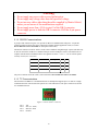
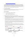
* Make sure that your GLK12232-25-WBL is equipped with the proper connector for use with this cable.
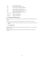
This connector (shown in Error! Reference source not found.) can be specified at time of order.
GLK12232-25
PC
+5V power
Figure 1-1 Connections for Testing
1. Refer to the diagram above for the following steps.
2. Wire the connector to the power supply. On most connectors the RED lead will go to +5V and the
BLACK lead to GND. Note: The manufacturer's warranty is void if the unit is subjected to overvoltage or reversed polarity.
3. Connect the GLK12232-25-WBL to the PC using the serial cable and adapter if required.
5
4. Connect the power connector, making sure that the +5V goes to V+ as shown in the diagram. Turn on
the power: the LCD backlight should come on.
Now you're ready to try it out.
1.6 Trying Out your GLK12232-25-WBL
The unit is connected to power and the PC and the backlight is on. You're ready to make sure it's working
properly.
1.
Use the mogd.exe program to exercise some of the features of the GLK12232-25-WBL to make sure
everything works properly.
2.
To experiment with typing text, run a PC terminal program, such as Hyperterm. Make sure it's
configured to use the correct port. Set the baud rate to 19,200.
If you type characters on the keyboard, they should now appear on the GLK12232-25-WBL screen. Note
that CR, backspace, etc., won't have any effect. Text will wrap around to the next line when you reach the
end of a line.
If you've reached this point and operation is normal, you can be confident that your GLK12232-25-WBL
works properly.
1.7 Trying out a Keypad
Since a number of different keypad types can be connected to the GLK12232-25-WBL, the results you get
may be a little unpredictable. At this point all we need to do is make sure that your keypad and interface
work, and possibly generate an ASCII map for your programming needs.
The keypad interface on the GLK12232-25-WBL converts a row/column connection to an ASCII character.
By default, a keypress is transmitted as serial data immediately. Keypad buffering can be selected using the
appropriate commands.
1.7.1 Here's what to do:
1.
Your PC should be running a terminal program, such as Hyperterm (as in the previous section).
2.
With the GLK12232-25-WBL connected to the PC, plug in your keypad. If your connector has fewer
pins than the one on the GLK12232-25-WBL, center it as well as possible.
Note 1: The keypad connector must be wired with columns on one side and rows on the other side of
the center of the connector. If your keypad isn't wired this way you will need to make an adapter or
rewire the connector to meet this requirement.
Note 2: The connector is reversible. Reversing the connector will not damage the keypad or the
GLK12232-25-WBL, but it will change the ASCII character map.
3.
Press a key on the keypad. An upper case ASCII character (A-Y) should appear on the PC screen.
Different keys should generate different characters.
If you want to experiment, reverse the connector and see if it generates a more logical set of characters.
Ultimately, the program in your controller will have to "map" these characters to the ones marked on the
keypad, which will likely be different.
6
1.8 Manual Override
Manual override should only be required in one instance. If for some reason the module is set at a baud rate
which cannot be produced by the host system and all communication to the display is lost, then the user
should follow this simple procedure:
1.
2.
3.
4.
5.
6.
Turn off the display
Put a jumper on pins 5 and 6 of the keypad connector (C5 and R1).
Power up the display. The baud rate is now set to 19,200.
Remove the jumper and change the RS-232 port settings to the desired baud rate.
Turn off the display.
Power up the display.
Refer to the “Set RS-232 Port Speed” command (section 7.1.10) for acceptable baud rates.
Note: This procedure does not change settings in the memory chip, it uses default settings stored in the main
processor. This allows the user to communicate with the display when all other communications are lost.
Once able to communicate with the display, the user may then change the default settings in the memory
chip.
7
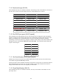
2. Connections
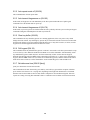
2.1 Connector Pinout
Refer to the diagram below for this chapter.
Figure 2-1 Electrical Connections
All connections are made via a 25 pin inline connector area near the bottom edge of the PCB. Pin
descriptions are as follows:
Pin
Marked
Function
Pin
Marked
Function
1
Yellow
do not use
14
C1
Keypad column 1
2
Black
ground
15
C2
Keypad column 2
3
Black
ground
16
C3
Keypad column 3
4
Red
+5V power input
17
C4
Keypad column 4
5
SCL
I C clock
2
18
C5
Keypad column 5
2
6
SDA
I C data
19
R1
Keypad row 1
7
GND
ground
20
R2
Keypad row 2
8
Rx
RS-232 receive data
21
R3
Keypad row 3
9
Tx
RS-232 transmit data
22
R4
Keypad row 4
10
+5V
+5V power input
23
R5
Keypad row 5
11
G1
General purpose output 1
24
Rst
do not use
12
G2
General purpose output 2
25
Cont
do not use
13
GND
ground for GPOs
2.1.1 Power Connections
Power is applied via pins 4 or 10. Power requirement is +5 VDC ±0.25V. Two connections are provided for
convenience depending on the type of connector installed.
8
Warning:
Do not apply any power with reversed polarization.
Do not apply any voltage other than the specified voltage.
Do not use any cables other than the cables supplied by Matrix Orbital,
unless you are aware of the modifications required.
Do not apply more than +5Vdc to pin #9 of the DB-9 connector.
Do not apply power to both the DB-9 connector AND the 4-pin power
connector.
2.1.2 RS-232 Communications
A group of four connections (pins 7-10) provide for RS-232 communications and power. A 4 pin SIP
connector soldered to these pins can be connected to a Matrix Orbital-supplied PC cable (see section
Error! Reference source not found. for description of this cable).
The RS-232 connector on the PC cable is wired so that a standard “straight through” 9 pin D-sub cable may
be used to connect the modules to a standard serial port such as COM ports on PCs. Note that this device
complies with the EIA232 standard in that it uses signal levels from +/- 3V to +/- 12V. It will not operate
correctly at TTL (0 to +5V) levels.
Pin Number
2
Direction
Description
Data from LCD Data Out (LCD)
LCD Host
Tx
Rx
3
Data to LCD
Data In (LCD)
Rx
Tx
5
-
Ground
gnd
gnd
The power connector on the PC cable is wired as shown in Error! Reference source not found..
2.1.3 I2C Communications
The GLK12232-25-WBL I2C communications runs at 100 kBps and supports up to 127 units on a single
communications line. The I2C data line operates on 5 volt CMOS levels. The power connector is also the
I²C communication line.
Figure 2-2 Power and I2C connector
Pin 1
Pin 2
Pin 3
Pin 4
Vdc
SCL (I²C clock)
SDA (I²C data)
Ground
9
The idea of ACK is to indicate when the data has been received correctly. ACK does not indicate data
incorrectly received. ACK simply fails to indicate when data is correctly received. Clearly, this is of limited
usefulness and even less so with Matrix Orbital modules. Matrix orbital modules are not capable of failing
to acknowledge an incorrectly received byte in response to that bytes transition. They are only capable of
failing to acknowledge the bytes following the byte, which was not received. To fully understand the
reasons for this one needs to understand something about how a Matrix Orbital module processes data.
Basically the reason why a Matrix Orbital module might fail to receive a byte correctly is that it was unable
to process the byte previous before the failed byte was transmitted. Because the module cannot possibly
know that it would be unable to store the byte before the next byte was received it cannot know to not ACK.
The reason for this situation in deference to situations you might be familiar with (i.e. memory chips, etc…)
is that the Matrix Orbital module employs a microprocessor to perform these data storage functions. A
memory chip takes care of these things entirely with in hardware subsystems that operate at the same speed
as the transmission themselves.
The GLK12232-25-WBL uses a standard Phillips 7bit address as defined by Phillips. How ever, we at
Matrix Orbital specify I2C address in 8bits. The 8th bit, least significant bit (LSB or Low Order Bit) of the
8bit address is read/write bit. If we take a standard Phillips 7bit address of 45hex this would be in binary
1000101. This is 7bits. If one adds the read write bit to this 7bit address and you assume that you are
writing one gets 10001010. Matrix Orbital would describe the Philips I2C address of 45hex as 8Ahex. The
read address would be 8Bhex.
For more information on Phillips I2C please visit…
http://www.ping.be/~ping0751/i2cfaq/i2cindex.htm
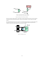
2.2 General Purpose Outputs
The GLK12232-25-WBL has two general purpose outputs, G1 and G2. These are provided to control relays
or other electronic devices. This allows external devices to be turned on or off using your PC or controller
and software commands. (See sections 7.1.6 and 7.1.7 for the command syntax.)
The two outputs differ slightly in specification:
G1 provides an output which is switched LOW when ON. When G1 is OFF it is pulled up to +5V
through 150 kohms, in other words it can only be used to "ground" an external device. Maximum
current is 20 mA.
G2 provides an output which is switched LOW when ON. When G2 is OFF it is pulled up to +5V,
supplied by the module. Maximum current is 20 mA.
Both outputs are referenced to ground.
Typical use of these outputs is shown in Figure 2-3.
10
+5V
gnd
G2
load
load
G1
GND
GND
Note: load must be 250 ohms minimum
Figure 2-3Using the General Purpose Outputs
If the device which is being driven by a GPO requires a relatively high current (such as a relay) it must have
an internal resistance greater than 250 ohms, or must be current limited to 20 mA by means of a suitable
resistor.
Note: The GPOs do not have any over current or over/under voltage protection so care must be taken when
using them. For instance if the external device is a relay it must be fully clamped (using a diode and
capacitor) to absorb any generated back electro-motive force (EMF).
10 - 100 uF
G2
+
Relay
coil
GND
1N4001
Figure 2-4 Clamping a Relay
11
3. Displaying Text
This chapter describes the various text-display commands in detail. A quick reference summary of all text
commands is found in section 8.3.
3.1 General
Text is displayed on the GLK12232-25-WBL using fonts saved in its internal flash memory. The
GLK12232-25-WBL is supplied with a 5 x 7 font installed. If this suits your needs you don't need to install
any other fonts. If you prefer to install your own fonts, instructions are given in section 6.2.
3.2 Writing Text to the Display
When the display receives a character, it displays that character at the position currently defined. The next
character sent to the module then advances to the following position on the display. Characters are drawn
using the currently selected font, and only characters defined in the current font are actually processed.
Characters that are not defined by the current font are ignored, and the positioning is not advanced for the
next character.
The position where text is to be displayed is a single pixel location stored in the GLK's volatile memory and
maintained internally by the GLK's firmware. It can be manually manipulated with two commands:
Set current text position (254 71 [col] [row]) positions the characters using a text oriented coordinate
system, dividing the display into character cells.
Set text cursor - pixel values (254 121 [x][y]) Sets text cursor to position (x,y), where x and y are in pixels.
Value is top left corner of next text character. This positions the character at a specific pixel, allowing more
"fine grained" control when needed.
3.3 Text Commands
In this section commands are identified by their names and decimal values. Hex and ASCII equivalents are
given in the summary (Table 8-1).
3.3.1 Auto scroll on (254 81)
When auto scrolling is on, it causes the GLK to shift the entire display’s contents up to make room for a
new line of text when the text reaches the scroll position defined by the “Set Font Metrics” command in the
GLK memory (normally the bottom right character position - default value for the GLK12232-25-WBL is
32).
3.3.2 Auto scroll off (254 82)
When auto scrolling is disabled, text will wrap to the top left corner of the display area. Existing graphics or
text in the display area are not erased before text is placed; when using proportional fonts without auto
scrolling, care should be taken to clear areas where text is being written, particularly when wrapping occurs.
This may be done using the Draw Solid Rectangle command (see section 4.2.6) with the colour set to white.
3.3.3 Set text insertion point (254 71 [col] [row])
This command sets the insertion point to the [column] and [row] specified. The insertion point is positioned
using the base size of the current font (this command does not position the insertion point at a specific
pixel). The pixel column used is determined by multiplying the width of the widest character in the font by
[column]. The pixel row used is determined by multiplying the height of the font by [row + interline
12
spacing] (see Set font metrics, below). If precise pixel-based text positioning is required, see "Set text
insertion point – pixel values", below.
3.3.4 Set current text insertion point to top Left (254 72)
This command moves the text insertion point to the top left of the display area, based on the metrics of the
current font. Refer to the "Set Font Metrics" command below for more details.
3.3.5 Set text insertion point using pixel values (254 121 [x][y])
This command sets the next position for text placement to an individual pixel location. The coordinate ([x
position],[y position]) defines a pixel on the screen where the top left corner of the screen is defined as
(0,0). This pixel location will be used as the top left corner of the next character of text which is sent to the
module without any regard to "font metrics" like character spacing or line spacing.
3.3.6 Set current font (254 49 [font ID])
This command instructs the GLK12232-25-WBL to use the font specified by [font identifier] as the default
font. The value specified should refer to a font already present in the GLK12232-25-WBL's memory.
Note: the font ID is established when the font is saved to the GLK12232-25-WBL, normally using the
mogd.exe program. The installed 5x7 font ID is “1”, unless changed by user.
3.3.7 Set font metrics (254 50 [metrics])
Where [metrics] = [left margin][top margin][x space][y space][scroll row]
This command defines the metrics of a font already present in the GLK12232-25-WBL's memory.
[left margin] specifies the first pixel column to use for the first character in a row. In some instances, a
font may not evenly fit on the screen, and dividing the extra space between the margins will improve
the overall appearance of the font.
[top margin] specifies the top pixel row to begin drawing the first row of text on the display area.
[x space] specifies the number of pixels to place between characters (i.e. character spacing).
[y space] specifies the number of pixels to place between rows of text (i.e. line spacing).
[scroll row] specifies the pixel row where scrolling should start (or, if auto scrolling is off, where
wrapping should occur). Typically, this value should be set to the first pixel row immediately below the
last row of text that will fit the display.
13
4. Displaying Graphics
This chapter describes the various graphics-display commands in detail. A quick reference summary of all
graphics commands is found in section 8.4.
4.1 General
Since the GLK12232-25-WBL is a bit mapped device, it may be used to display graphics. Graphic images
may be created by means of a pixel-oriented graphics program, saved as bitmaps, and loaded into the
GLK12232-25-WBL using the mogd.exe program. Images may be saved in the GLK12232-25-WBL's
memory, and displayed upon command, or they may be downloaded "on the fly" (inline) during
GLK12232-25-WBL operation.
Note that "saved" and "on the fly" graphics images are processed differently. These differences must be
taken into account when processing graphics.
Saved bitmaps use each byte (8 bits) to represent a vertical column of 8 pixels. The next byte represents the
next column to the right If the graphic is "taller" than 8 pixels, the LSB of the next data byte will be the next
pixel. Orientation is top to bottom – LSB to MSB. Pixels/bits are “packed” – that is, if the height of the
graphic is not an even multiple of 8, the leftover bits go on the next X column to the right), etc. (see the
figure below).
Inline bitmaps are processed horizontally, and each byte represents a horizontal row of 8 bits, with the next
byte representing the next 8 bits to the right Orientation is left to right – MSB to LSB, which is the opposite
to the serial transmission sequence (bytes are sent LSB first).
Saved Bitmap
16 pixels high
lsb
Byte 1
msb
lsb
Byte 2
msb
lsb
Byte 3
msb
lsb
Byte 4
msb
Inline Bitmap
20 pixels high
lsb
Byte 1
msb
lsb
Byte 2
msb
lsb
Byte 3
16 pixels wide
Byte 3
msb
Byte 1 lsb msb Byte 2
lsb
msb
lsb
msb
Byte 3 lsb msb Byte 4
lsb
Byte 4
msb
lsb
Note: inline bitmaps must
be a multiple of 8 pixels
wide.
Byte 5
msb
Figure 4-1 Graphic bitmaps
Each pixel in a bitmap is described by a single bit, and may only have the values ON or OFF, i.e. shades of
gray are not supported.
4.2 Graphics Commands
In this section commands are identified by their names and decimal values. Hex and ASCII equivalents are
given in the summary (Table 8-2).
14
The coordinate origin (0,0) is at the top left corner of the display. X values go from 0 to 121 (increasing
towards the right) and Y values go from 0 to 31 (increasing towards the bottom).
4.2.1 Set drawing color (254 99 [color])
This command sets the drawing color for subsequent graphic commands that do not have the drawing color
passed as a parameter. The parameter [color] is the value of the color where white 0 Hex, and black is 255
Hex. Note: All non-zero values will display as black.
4.2.2 Draw line (254 108 [x1][y1][x2][y2])
This command will draw a line from (x1,y1) to (x2,y2) using the current drawing color. Lines may be drawn
from any part of the display to any other part, but may be important to note that the line may interpolate
differently right to left, or left to right. This means that a line drawn in white from right to left may not fully
erase the same line drawn in black from left to right.
4.2.3 Continue line (254 101 [x][y])
This command will draw line with the current drawing color from the last line end (x2,y2) to (x,y). This
command uses the global drawing color so the Set Drawing Color command should be used before the first
line segment if required.
4.2.4 Put pixel (254 112 [x][y])
This command will draw a pixel at (x,y) using the current drawing color. The unit processes these requests
fast enough to keep up with a steady stream at 115 kbaud, so flow control is not required.
4.2.5 Draw outline rectangle (254 114 [color][x1][y1][x2][y2])
This command draws a rectangular box in the specified color (0 = white, non-zero = black). The top left
corner is specified by (x1,y1) and the bottom right corner by (x2,y2).
4.2.6 Draw solid rectangle (254 120 [color][x1][y1][x2][y2])
This command draws a solid rectangle in the specified color (0 = white, non-zero = black). The top left
corner is specified by (x1,y1) and the bottom right corner by (x2,y2). Since this command involves
considerable processing overhead, we strongly recommend the use of flow control, particularly if the
command is to be repeated frequently (see section 4.3).
This procedure is common for monitoring applications where there is a “field” on the display that is
constantly being updated from, say, a temperature sensor.
4.2.7 Initialize bar graph (254 103 [ref][type][x1][y1][x2][y2])
This command initializes a bar graph referred to by number [reference number] of type [type] with size
from (x1,y1) (top left) to (x2,y2) (bottom right). A maximum of 16 bar graphs with reference numbers from 0
to 15 can be initialized as:
[type = 0]
Vertical, bottom referenced
[type = 1]
Horizontal left referenced
[type = 2]
Vertical top referenced
[type = 3]
Horizontal right referenced
15
The bar graphs may be located anywhere on the display, but if they overlap, they will not display properly.
Note: it is important that [x1] is less than [x2], and [y1] is less than [y2].
This command doesn't actually draw the graph, it must be "filled in" using the Write to bar graph command,
described below. The unit saves time by only drawing that part of the bar graph which has changed from the
last write, so the representation on the screen may not survive a screen clear or other corrupting action. A
write of value zero, followed by new values will restore the proper look of the bar graph.
4.2.8 Write to bar graph (254 105 [reference number][value])
Once the bar graph has been initialized it can be "filled in" using this command. This command sets the bar
graph [reference number] to value [value]. [value] is given in pixels and should not exceed the available
height/width of the graph. (If it does, the graph will simply be written to its maximum size.)
4.2.9 Display saved bitmap (254 98 [reference number][x][y])
This command causes a previously stored bitmap referenced by [reference number] to be displayed to the
screen at pixel location (x, y) where this location defines the top left corner of the bitmap. Note: The
reference number is established when the bitmap is saved, normally using mogd.exe. Bitmaps and fonts
may use the same reference numbers, i.e. you can have both a bitmap 1 and a font 1.
4.3 Flow Control
The GLK12232-25-WBL has built-in flow control which is very useful during direct bitmap display and
multiple pixel placement. Flow control is enabled or disabled by two commands (see Table 8-5 and the next
two sections). If flow control is enabled, the GLK12232-25-WBL will return an "almost full" message
(0xFE) to the controller when its internal buffer fills to a defined level, and an "almost empty" message
(0xFF) when the buffer contents drop to a defined level.
4.3.1 Enter Flow Control Mode (254 58 [full][empty])
Note: Flow control applies only to the RS-232 interface. It is not available for I2C.
This command enables flow control. When the buffer fills so that only [full] bytes are available the
GLK12232-25-WBL will return an "almost full" message (0xFE) to the controller. When the buffer empties
so that only [empty] bytes remain the GLK12232-25-WBL will return an "almost empty" message (0xFF) to
the controller.
The GLK12232-25-WBL will return the "almost full" message for every byte sent to the GLK12232-25WBL until the used buffer space once more drops below the [full] level.
Whether the user is in ‘Flow Control Mode’ or not, the module will ignore display or command bytes which
would overrun the buffer. While in ‘Flow Control Mode’ the unit will return 0xFE when buffer is almost
full even though it may have already thrown rejected data away. The buffer size for the GLK12232-25WBL is 96 bytes.
When using this command in an application, selection of the value for the buffer almost full should be
considered very carefully. This is a critical aspect of using this command to it’s full potential. When using a
host system or PC which contains a FIFO, the user should set the value of equal to or greater than the size
of the FIFO. The reason for this is that the FIFO may be full when the host system receives 0xFE. In the
case of 16550 UART the size at its maximum is 16, therefore the value of should be set to 16 or greater.
This mode must not be used during loading of fonts and bitmaps. It is highly recommended for use
with direct screen write and multiple pixel placements.
16
4.3.2 Exit Flow Control Mode (254 59)
This command turns off flow control. Bytes may overflow the buffer without warning.
17
5. Keypad Interface
This chapter describes the keypad interface and associated commands in detail.
5.1 General
The GLK12232-25-WBL keypad interface processes the keypad row/column matrix into a serial (RS-232
or I2C) data byte stream. Aside from this processing, the keypad has no effect on the GLK12232-25-WBL
display. If you need to send keystrokes to the display, they must be routed through your controller.
5.2 Connections
Figure 5-1 Keypad Connector
The connector is not "keyed" so your keypad will probably plug in either of two ways. The GLK12232-25WBL will not be damaged by reversing the connector, but your keypad will generate a different ASCII
character mapping for each position. If your connector has fewer than 10 pins it should probably be
centered on the GLK12232-25-WBL connector.
The returned key codes are as follows, but note that your keypad may be laid out in a different pattern. If
this is the case, you will need to interpret the key codes differently. The diagram 1 shows the logical layout
(row 1, column 1 in upper left). The connector for the keypad is a 10 pin 0.1" spacing male header. Pin 1 is
indicated in Figure 2-1. Pins 1 through 5 are columns and pins 6 through 10 are rows. The keypad is
scanned whenever a key is pressed: there is no continuous key scan. This means that key presses are dealt
with immediately without any appreciable latency. This also prevents electrical noise which is often caused
by continuous key scans.
Rows
1
2
3
4
5
1
A
F
K
P
U
Columns
2
3
B
C
G
H
L
M
Q
R
V
W
4
D
I
N
S
X
5
E
J
O
T
Y
Note: The keypad connector must be wired with columns on one side and rows on the other side of the
center of the connector. If your keypad isn't wired this way you will need to make an adapter or rewire the
connector to meet this requirement.
5.3 I2C Interface
The keypad is read by I²C master read. In short, this means that a read of the module will always return the
first unread key press. A read is initiated by writing to the module with its base address plus 1, then
clocking the module’s return byte after the module releases the SDA line. Much more detail on this basic
I²C function can be found in the I²C specification by Philips. A good reference is also available at
18
http://www.ping.be/~ping0751/i2cfaq/i2cindex.htm
The module contains a ten key press buffer so that it can be polled for key presses at an infrequent rate
(every 500 to 1000 mS is typical). All returned key presses indicate the presence or absence of additional
logged key presses by the most significant bit (MSB - bit 7). If the user has pressed two keys since the last
poll of the keypad interface, the first read will return the key code with bit 7 set and the second read will
return the key code with bit 7 clear. The application must take into account this bit to keep up with user key
presses. If there are no keypresses detected, the module will return zero (0x00).
5.4 RS-232 Interface
By default on any press of a key, the module will immediately send out the key code at the selected baud
rate. This behavior can be modified using commands found in the next section.
5.5 Commands
5.5.1 Auto repeat mode on (254 126 [mode])
[mode] = 0 gives Resend Key Code mode
[mode] = 1 gives Key down / Key up code mode
Two Modes of auto repeat are available and are set via the same command.
1.
Resend Key Code: This mode is similar to the action of a keyboard on a PC. In this mode, when a key
is held down, the key code is transmitted immediately followed by a 1/2 second delay. After this delay,
key codes will be sent via the RS - 232 interface at a rate of about 5 codes per second. This mode has
no effect if polling or if using the I²C interface.
2.
Key down / Key up codes: This mode may be used when the typematic parameters of the Resend Key
code mode are unacceptable or if the unit is being operated in polled mode. The host system detects the
press of a key and simulates an auto repeat inside the host system until the key release is detected.
In this mode, when a key is held down, the key code is transmitted immediately and no other codes will
be sent until the key is released. On the release of the key, the key release code transmitted will be a
value equal to the key down code plus 20 hex. For example, the key code associated with key 'P' (0x50)
is pressed, the release code is 'p' (0x70).
In RS-232 polled mode (see 5.5.4 below) or via the I²C interface, the key down / key up codes are
used; however, the user should be careful of timing details. If the poll rate is slower than the simulated
auto – repeat it is possible that polling for a key up code will be delayed long enough for an unwanted
key repeat to be generated (see Figure 5-2).
Polls
Key up
Key down
auto-repeat clock
valid key stroke
(before key up)
unwanted auto-repeat
after key-up.
Figure 5-2 Poll timing
19
5.5.2 Auto repeat mode off (254 96)
This command turns off auto repeat mode.
5.5.3 Auto transmit keypresses on (254 65)
In this mode, all keypresses are sent immediately to the host system without the use of poll keypad
command. This is the default mode on power up.
5.5.4 Auto transmit keypresses off (254 79)
In this mode, up to 10 keypresses are buffered until the unit is polled by the host system via the poll keypad
command. Issuing this command places the unit in polled mode.
5.5.5 Clear key buffer (254 69)
This command clears any unread keypresses. In a menuing application, if the user presses a key which
changes the menu context, any following key presses may be inaccurate and can be cleared out of the buffer
between menu changes to prevent jumping around the menu tree. It may also be used to, in effect, reset the
keypad in case the host application resets for whatever reason.
5.5.6 Poll keypad (254 38)
This command returns any unbuffered keypresses via the RS - 232 interface. The host system must be set up
to receive the key codes. When the GLK12232-25-WBL receives this command it will immediately return
any unbuffered keypresses which may have not been read already. If there is more than one keypress
buffered, then the high order bit (MSB) of this returned keycode will be set (1). If this is the only buffered
keypress, then the MSB will be reset (0). If there are no buffered keypresses, then the returned code will be
0x00. Please note to make use of this command the “Auto Transmit Keypress” mode should be off.
5.5.7 Set debounce time (254 85 [time])
[time] is in increments of 6554 microseconds.
This command sets the time between key press and key read. All key types with the exception of latched
piezo switches will “bounce” for a varying time, depending on their physical characteristics. The default
debounce time for the module is about 52 mS, which is adequate for most membrane keypads. This time
equates to a setting of 8 using this command as there is a debounce time resolution of 6554 microseconds.
20
6. Fonts and Graphics Files
6.1 General
Matrix Orbital graphic modules contain a sophisticated file system for storing and retrieving font
information, bitmaps and system parameters; not unlike the way that a computer deals with files on a hard
drive. However, the modules use no moving parts, therefore, data is stored far more reliably than data on a
home PC.
Operationally, there is one important difference between the Matrix Orbital file system and that of a PC.
While a PC will allow fragmentation of its files across the available file space, the Matrix Orbital file
system takes great care to ensure that all parts of a file are stored together. This system works well to
maximize storage space and operational efficiency, however, during file downloads, the modules may need
to spend considerable time moving files to make room for the new file. This delay during download can be
as much as a minute, but generally it will not exceed 10 seconds.
When a file is being downloaded with the same "name" or reference number as previously existing file, the
old file needs to be deleted first. Since we cannot know if the new file is exactly the same size as the old
file, that space vacated by the old files filled by moving previously existing files down to fill up the vacated
space. This ensures that no file space is wasted.
Of course, the average module will simply have files loaded into it and it will then get to work, without ever
having to perform this file reorganization task. The file space may be rewritten up to 100 000 times, but
most users will simply load in their fonts and bitmaps once and that will be it.
6.2 Using mogd.exe
The Matrix Orbital Interface program "mogd.exe", which is provided on the disk and the website, generates
and saves fonts larger than 14 pixels in height. It is also used to save graphic images (bitmaps) to the
GLK12232-25-WBL.
To make use of smaller fonts it is recommended that you use a pre-generated font. You will find these fonts
on the disk or the website. Unfortunately, integrating these fonts is not as straight forward as generating the
fonts yourself. To make use of these fonts you must place the font files in your font directory as defined in
the interface program. You can find and define this directory under "settings".
A font file consists of a single file with an extension .mgf and a directory which contains bitmaps for every
character. All .mgf files are contained within the font directory and all bitmap directories are sub directories
of the font directory. After download of a font file use a “Zip” program to “UnZip” the .mgf file and bitmap
sub-directory into your font directory. Start or restart mogd.exe and click on the font tab. You should now
see your new pre-generated font listed in the font list of mogd.
6.3 Commands
In addition to the commands listed below, you may use the mogd.exe program to save fonts and bitmaps to
the GLK12232-25-WBL's flash memory.
6.3.1 Erase file (254 45 [type] [ref])
This command erases a file within the GLK12232-25-WBL memory. This command erases a single file at a
time.
This command needs to be given two parameters: [type] and [ref]. The file type and reference number are
defined when the file is saved to the GLK12232-25-WBL using mogd.exe. Since there is no command to
list files in memory, the user must keep track of the memory contents.
21
[type] = 1 is a font file
[type] = 5 is a bitmap
Once this command is completed all files “move up” and recover the empty space for efficient memory
management.
6.3.2 Purge memory (254 33 89 33)
This command completely erases the GLK12232-25-WBL's non-volatile memory. This removes all fonts,
font metrics, bitmaps, and settings (current font, cursor position, communication speed, etc.). It is an "odd"
command in that it is three bytes in length. This is to prevent accidental execution.
6.3.3 Upload Font (254 36 [ref] [file size] [file data])
This command begins a font upload to the GLK12232-25-WBL's non-volatile memory. [ref] is the
reference number to be used for this font. File size is a 2 byte value that must be calculated by the host
before the transfer takes place. See section 6.4 for details.
6.3.4 Upload Bitmap (254 94 [ref] [file size] [file data])
This command begins a bitmap upload to the GLK12232-25-WBL's non-volatile memory. [ref] is the
reference number to be used for this bitmap. File size is a 2 byte value that must be calculated by the host
before the transfer takes place. See section 6.5 for details.
6.4 Working with Font Files
A font file consists of a header, a character list, and character bitmaps.
The header consists of:
Placeholder for actual EOF (2 bytes, use 0xFF 0xFF – these bytes will be set to their final value by the
module)
Nominal character width (1 byte)
Absolute font height (1 byte)
ASCII value of first character defined in this file (1 byte)
ASCII value of last character defined in this file (1 byte)
The character list consists of groups of 3 bytes per character:
Offset to character bitmap (2 bytes)
Actual width of this character (1 byte)
The character bitmaps are described in section 6.4.3.
6.4.1 Font File in Table Form
The table below shows the layout of a font file in table form.
File Format (Font)
0xFF
Width
O-Low
O-High
Data
0xFF
O-High
Width
O-Low
Data
X size
O-Low
O-High
Width
Data
Y size
Width
O-Low
Data
Data
Start
O-High
Width
Data
Data
22
End
O-Low
O-High
Data
Data
O-High
Width
O-Low
Data
Data
O-Low
O-High
Width
Data
Data
Data
Data
Data
Data
Data
Data
Data
Data
Data
Data
Data
Data
Data
Data
Data
Data
Data
Data
Data
Data
Data
Data
Data
Data
Data
Data
Data
Data
Data
Data
Data
Data
Data
Data
Data
Data
Data
Data
Data
Data
Data
Data
Data
Data
Data
Data
Data
Data
Data
Data
Data
Data
Data
Data
Data
Data
Data
Data
Data
Data
Data
Data
Data
Data
Data
Data
Data
Data
Data
6.4.2 Uploading the File to the Module
The Upload Font command is used to actually upload the font file. Recall that the syntax for this command
is:
0xFE 0x24 [ref] [file size] [file data]
In this example the file size is 94 bytes (0x5E) and the reference number is 2. The communications
exchange between the host and the module looks like this:
Host sends
0xfe
'$' (command)
'2' (reference)
Module sends
'2' (echo reference)
0x01 (host confirms echo)
0x5e (low size)
0x5e (echo)
0x01 (host confirms echo)
0x00 (high size)
0x00 (echo)
0x01 (file fits)*
0xFF (first byte of data)
0xFF (echo)
0x01 (host confirms echo)
0xFF (second byte of data)
0xFF (echo)
0x01 (host confirms echo)
0x20 (third byte of data)
0x20 (echo)
0x01 (host confirms echo)
etc
* If the module detects that the file will not fit in the available memory when the file size has been
transmitted, it will send 0x08 instead of 0x01. In this case, the host should cease transmission. The
module will return to a ready state.
From this point, the module treats all data as raw and just stores it away. The module will store the data,
then read it back from memory and send the read value back to the host. If the host system receives an
incorrect echo, it should send status as 0x08 instead of 0x01. This will terminate the transfer. Upon
termination, the module will delete the partially completed file and return to a ready state.
23
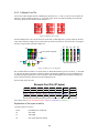
6.4.3 A Sample Font File
Let's look at a short sample font file containing only the letters "h", "i" and "j". First we need to define the
font size. For this example we'll use a 5 x 7 pixel font. Next, we have to draw the bitmaps for each of the
characters. We'll use the examples shown in Figure 6-1.
Figure 6-1 Bitmaps for h, i and j
Now the bitmaps have to be converted to bytes. If the font is 8 bits high, this is a pretty simple job because
each vertical column is simply one byte (lsb at the top). In this case, however, the font is only 7 bits high so
the bytes "wrap around" as shown in Figure 6-2.
7F
lsb
byte 5 overflow (ignored)
byte 5
byte 1
byte 4
byte 2
04
81
80
07
1
2
4
8
1
2
4
8
Bytes "straightened out"
byte 3
Figure 6-2 Bytes for a 7 bit high font
We've marked in the bits that are set for the letter "h". Remember that the bytes are "inverted", i.e. the LSB
is at the top. Each byte is shown in a different colour in the diagram. When the bytes are straightened out,
it's simple enough to find their hex values, which are shown in the diagram above each byte. Trailing zero
bytes at the end of narrow characters are not included in the file.
Now let's look at the file itself.
Example Font File (27 bytes)
0xFF
0x05
0x04
0x20
0xFF
0x00
0x81
0xB1
0x05
0x14
0x80
0x07
0x07
0x03
0x07
0x68
0x00
0xC4
0x6A
0x17
0x3E
0x00
0x04
0x10
The colours refer to: Font information header, character 'h', character 'i', character 'j'.
Explanation of the bytes in the file:
(All values below are in hex)
FF FF
05
07
68
placeholders for actual EOF
font width
font height
first ASCII character defined
24
0x0F
0x7F
0x02
70
00 0F
05
00 14
03
00 17
04
7F 04 81 80 07
C4 3E 10
02 20 B1 07
last ASCII character defined
offset to definition of first character (h)
number of bytes in definition of first character
offset to definition of second character (i)
number of bytes in definition of second character
offset to definition of third character (j)
number of bytes in definition of third character
definition of first character
definition of second character
definition of third character
6.5 Working with Bitmap Files
Uploading a bitmap is the same as uploading a font file except that the character header information is not
required.
The bitmap file consists of a header followed by the bitmap data. The header format is as follows:
Placeholder for actual EOF (2 bytes, use 0xFF 0xFF – these bytes will be set to their final value by the
module)
x size of bitmap (1 byte)
y size of bitmap (1 byte)
Bitmap data follows with the bits organized vertically from the top left (see Figure 4-1). The last byte may
be padded with zeros.
Aside from the different header, bitmap file operations are identical to those described for font files in
section 6.4.
25
7. Miscellaneous Commands
The commands listed in this chapter don't readily fit in any of the other categories, or are used in more than
one category.
7.1.1 Clear display (254 88)
This command clears the display and resets the text write position to the top left of the screen.
7.1.2 Set contrast (254 80 [contrast])
This command sets the display's contrast to [contrast], where [contrast] is a value between 0x00 and 0xFF
(between 0 and 255). Lower values cause "on" elements in the display area to appear lighter, while higher
values cause "on" elements to appear darker.
Lighting conditions will affect the actual value used for optimal viewing. Individual GLK12232-25-WBL
modules will also differ slightly from each other in appearance. In addition, values for optimal viewing
while the GLK12232-25-WBL backlight is on may differ from values used when backlight is off.
7.1.3 Set contrast and save (254 145 [contrast])
This command works in exactly the same way as the “Set Contrast” command. The only difference is it
saves the contrast value in the memory of the module, whereas, the previous command only changes the
value for the duration of use.
7.1.4 Backlight on (254 66 [minutes])
This command turns on the backlight for a time of [minutes] minutes. (this specifies how long the backlight
will remain on after receipt of the command). If [minutes] is zero (0), the backlight will remain on
indefinitely. Note: backlight is always on by default on power up.
7.1.5 Backlight off (254 70)
This command turns the backlight of the GLK12232-25-WBL off.
7.1.6 General purpose output on (254 86 [gpo #])
This command turns ON either of the General Purpose Outputs (see section 2.2 for a description of the
GPO). [gpo #] is 1 for G1 or 2 for G2. Note that ON means that the output is pulled low.
7.1.7 General purpose output off (254 87 [gpo #])
This command turns OFF either of the General Purpose Outputs. [gpo #] is 1 for G1 or 2 for G2. For G1
OFF allows the output to "float". For G2 OFF pulls the output to +5V.
7.1.8 Set I2C address 254 51 [address])
This command sets the I²C write address of the module. This value must be an even number and the read
address is one higher. For example if the I²C write address is set to 0x50, then the read address is 0x51. The
change in address is immediate. This address is 0x50 by default, and is reset temporarily back to that value
when the "Manual Over-ride" jumper is used on power up (see section Error! Reference source not
found.).
26
7.1.9 Read module type (254 55)
This command will return, over the RS-232 interface, the model type value of the module. It will return a 1byte hex value. Values for various modules at the time of this publication are as follows:
LCD0821 - 0x01
LCD2021 - 0x03
LCD1641 - 0x04
LCD2041 - 0x05
LCD4021 - 0x06
LCD4041 - 0x07
LK202-25 - 0x08
LK204-25 - 0x09
LK404-55 - 0x0A
VFD2021 - 0x0B
VFD2041 - 0x0C
VFD4021 - 0x0D
VK202-25 - 0x0E
VK204-25 - 0x0F
GLC12232 - 0x10
GLC12864 - 0x11
GLC128128 - 0x12
GLC24064 - 0x13
GLK12864-25 - 0x14
GLK24064-25 - 0x15
GLK128128-25 - 0x21
GLK12232-25-WBL - 0x22
LK404-AT - 0x31
VFD1621 - 0x32
LK402-12 - 0x33
LK162-12 - 0x34
LK204-25PC - 0x35
7.1.10 Set RS232 port speed (254 57 [speed])
This command sets the GLK's RS232 port to the specified [speed]. The change takes place immediately.
[speed] is a single byte specifying the desired port speed. Valid speeds are shown in the table below. The
GLK can be manually reset to 19,200 baud in the event of an error during transmission (including
transmitting a value not listed below) by setting the "manual override" jumper on the GLK controller board
during power up (see section Error! Reference source not found.). This command is ignored until this
jumper is removed again.
Speed Value
Speed
20 Hex
9600 baud
0F Hex
19200 baud
95 Hex
57600 baud
03 Hex
76800 baud
8A Hex
115000 baud
7.1.11 Set Serial Number (254 52 [byte1] [byte2]
Modules may be delivered with the serial number blank. In this case the user may set the desired 2 byte
serial number using this one time only command.
Upon the execution of this command, the module will echo these two bytes back over the RS-232 interface.
The serial number may be set only once. Any future attempt to execute this command will result in no
change and the module will return to the originally set serial number.
7.1.12 Read Serial Number (254 53)
This command will return, over the RS-232 interface, the 2-byte serial number of the module as it was
previously stored.
27
7.1.13 Read Version Number 254 54)
This command will return the firmware version number of the GLK12232-25-WBL. It will return a 1-byte
hex value.
28
8. Appendix: Command Summary
8.1 General
The operation of the GLK12232-25-WBL is controlled by a simple and consistent command set.
Commands control
text display
graphics display
keypad interface
the GLK12232-25-WBL file system
miscellaneous operating parameters
This chapter includes summary tables of all commands. Individual commands are discussed in detail in
Chapters 3 to 7.
8.2 Issuing Commands
Commands are issued to the GLK12232-25-WBL by the controller. In a test setup, commands can be issued
to the GLK12232-25-WBL by means of a BASIC program, using the chr$( ) function. In the tables below,
we've shown commands in hex, ASCII and decimal form. All commands begin with the prefix character
0xFE (254 decimal). These commands are issued on the serial communications link (I2C or RS-232) at the
currently defined baud rate.
For example (using BASIC in a test setup), you could issue the command to clear the screen on the
GLK12232-25-WBL by including the line:
PRINT#1,chr$(254);chr$(88)
in your BASIC program. Or with C you could (using Zcomm serial library)
ZComm1->WriteCommByte(0xfe);
ZComm1->WriteCommByte('X');
8.3 Text Commands
See Chapter 3 for command descriptions.
Table 8-1 Text Commands
Command
Syntax
Default
Notes
Auto scroll on
FE 51
254 81
254 'Q'
off
Enables scroll at bottom of screen. Text will
push display up one line to make room for new
line.
Auto scroll off
FE 52
254 82
254 'R'
off
Disables auto scroll. Text will wrap to top left
and overwrite existing text.
29
Command
Syntax
Default
Notes
Set text insertion
point
FE 47 [col] [row]
254 71 [col] [row]
254 'G' [col] [row]
n/a
Sets text insertion point using the base size of
the current font
Set text insertion
point to top left
FE 48
254 72
254 'H'
Set text insertion
point using pixel
values
FE 79 [x][y]
254 121 [x][y]
254 'y' [x][y]
n/a
Sets text insertion point to position (x,y), where
x and y are in pixels. Value is top left corner of
next text character.
Set current font
FE 31 [font id]
254 49
254 '1'
n/a
Sets font to [font id]. Font must be in memory.
Set font metrics
FE 32 [metrics]
254 50 [metrics]
254 '2' [metrics]
n/a
For definition of [metrics] see section 3.3.7.
This command moves the text insertion point to
the top left of the display area, based on the
metrics of the current font. See "Set font
metrics" (section 3.3.7) for more details.
8.4 Graphics Commands
Table 8-2 Graphics Commands
Command
Syntax
Notes
Set drawing color
FE 63 [color]
254 99 [color]
254 'c' [color]
Sets color (0 = white, 255 = black) for the various
drawing commands.
Draw line
FE 6C [x1][y1][x2][y2]
254 108 [x1][y1][x2][y2]
254 'l' [x1][y1][x2][y2]
Draws a line from x1,y1 to x2, y2. x values are from 0
– 31 (decimal) and y values from 0 – 121 (decimal).
Continue line
FE 65 [x][y]
254 101 [x][y]
254 'e' [x][y]
Continues line from last line end (x2,y2) to (x,y). Uses
current drawing color.
Put pixel
FE 70 [x][y]
254 112 [x][y]
254 'p' [x][y]
Puts pixel in position (x,y). Uses current drawing color.
Draw outline
rectangle
FE 72 [color][x1][y1][x2][y2]
254 114 [color][x1][y1][x2][y2]
254 'r' [color][x1][y1][x2][y2]
Draws a rectangular outline using color [color].
Draw solid
rectangle
FE 78 [color][x1][y1][x2][y2]
254 120 [color][x1][y1][x2][y2]
254 'x' [color][x1][y1][x2][y2]
Draws a solid rectangle using color [color].
Initialize bar
graph
FE 67 [ref][type][x1][y1][x2][y2]
254 103 [ref][type][x1][y1][x2][y2]
254 'g' [ref][type][x1][y1][x2][y2]
Sets aside space for a bar graph. [ref] is reference
number (0-15) for use by the Write to Bar Graph
command. [type] has values:
0 = vertical, starting from bottom
1 = horizontal, starting from left
2 = vertical, starting from top
3 = horizontal, starting from right
30
Command
Syntax
Notes
Write to bar
graph
FE 69 [ref][value]
254 105 [ref][value]
254 'I' [ref][value]
Fills the bar graph referred to as [ref] from start to
[value]. [value] is in pixels.
Display saved
bitmap
FE 62 [ref][x][y]
254 98 [ref][x][y]
254 'b' [ref][x][y]
Causes bitmap [ref] to be displayed with its top left
corner starting at position (x,y).
8.5 Keypad Interface Commands
Table 8-3 Keypad Interface Commands
Command
Syntax
Default
Notes
Auto repeat mode on
FE 7E [0|1]
254 126 [0|1]
254 '~' [0|1]
off
Applies to keypad only. 0 = 200 ms typematic, 1
= key down/key up codes sent.
Auto repeat mode off
FE 60
254 96
254 '`'
off
Applies to keypad only.
Auto transmit
keypresses on
FE 41
254 65
254 'A'
on
Sets auto transmit mode for keypad.
Keypresses are transmitted to host without
polling.
Auto transmit
keypresses off
FE 4F
254 79
254 'O'
off
Up to 10 keypresses buffered until polled.
Clear key buffer
FE 45
254 69
254 'E'
n/a
Clear unread keypresses.
Poll keypad
FE 26
254 38
254 '&'
n/a
Returns buffered keypresses to application.
Returns 0x00 if no keypresses. High order bit
set unless this is the last/only keypress.
Set debounce time
FE 55 [time]
254 85 [time]
254 'U' [time]
52 ms
Resolution: 1 = 6.554 ms
31
8.6 File System Commands
In addition to these commands, the mogd.exe program (see section 1.4) is used to download fonts and
graphics to the GLK12232-25-WBL.
Table 8-4 File System Commands
Command
Syntax
Default
Notes
Erase file
FE B0 [type] [ref]
254 45 [type] [ref]
n/a
Erases file in memory. Type = 1 is font, type
= 5 is bitmap. [ref] is reference number.
Purge memory
FE 21 59 21
254 33 89 33
n/a
Removes all fonts, font metrics, bitmaps
and settings from memory.
Upload bitmap
FE 6E [ref] [size] [data]
254 94 [ref] [size] [data]
254 '^' [ref] [size] [data]
n/a
Uploads a bitmap to the memory of the
GLK12232-25-WBL. See section 6.5.
Upload font
FE 24 [ref] [size] [data]
254 36 [ref] [size] [data]
254 '$' [ref] [size] [data]
n/a
Uploads a font to the memory of the
GLK12232-25-WBL. See section 6.4.
8.7 Miscellaneous Commands
Table 8-5 Miscellaneous Commands
Command
Syntax
Default
Notes
Clear display
FE 58
254 88
254 'X'
n/a
Clears screen of text and graphics, places text
cursor at top left.
Set contrast
FE 50 [contrast]
254 80 [contrast]
254 'P' [contrast]
128
Sets display contrast. Compensates for viewing
angle. Contrast is a value between 0 and 255
(hex 0 to FF). Larger = darker.
Set contrast and save
FE 91 [contrast]
254 145 [contrast]
128
Same as "set contrast" but saves [contrast] as
default.
Backlight on
FE 42 [minutes]
254 66 [minutes]
254 'B' [minutes]
on
Backlight will stay on for [minutes]. If [minutes]
= 0 backlight will stay on permanently.
Backlight off
FE 46
254 70
254 'F'
on
Turns off backlight.
General purpose
output on
FE 56 [gpo #]
254 86 [gpo #]
254 'V' [gpo #]
off
Turns a general purpose output ON. [gpo #] is 1
for G1 or 2 for G2. See section 2.2 for further
details.
General purpose
output off
FE 57 [gpo #]
254 87 [gpo #]
254 'W' [gpo #]
off
Turns a general purpose output OFF. [gpo #] is
1 for G1 or 2 for G2. See section 2.2 for further
details.
32
2
Set I C address
FE 33 [address]
254 51 [address]
254 '3' [address]
0x50
Value is write address and must be even, read
address is 1 higher.
Read module type
FE 37
254 55
254 '7'
see table
Reads the module type. See table in section
7.1.9. Returns a 1-byte hex value.
Set RS232 port
speed
FE 39 [speed]
254 57 [speed]
254 '9' [speed]
19,200
Sets RS232 speed. See table in section 7.1.10.
Enter flow control
mode
FE 3A [full] [empty]
254 58 [full] [empty]
254 ':' [full] [empty]
off
Sets "full" and "empty" marks for the 96 byte
display buffer. When buffer reaches [full]
display will return 0xFE to host. When buffer
reaches [empty] display will return 0xFF.
Exit flow control
mode
FE 3B
254 59
254 ';'
Turns off flow control (buffer handshaking).
Set Serial Number
FE 34 [byte1][byte2]
254 52 [byte1][byte2]
254 '4' [byte1][byte2]
This is a one-time-use command which works
only on units without factory set serial numbers.
Read Serial Number
FE 35
254 53
254 '5'
Reads the two byte serial number of the
module.
Read Version
Number
FE 36
254 54
254 '6'
Reads the firmware version number of the
module. Returns a 1-byte hex value.
33
9. Appendix: Specifications
Environmental Specifications
Standard Temperature
Operating Temperature
0°C to +50°C
Storage Temperature
-20°C to +70°C
Operating Relative Humidity
90% max non-condensing
Vibration (Operating)
4.9 m/s² XYZ directions
Vibration (Non-Operating)
19.6 m/s² XYZ directions
Shock (Operating)
29.4 m/s² XYZ directions
Shock (Non-Operating)
490 m/s² XYZ directions
Electrical Specifications
Supply Voltage
4.75 - 5.25 Vdc
Supply Current
18 mA typical
Supply Backlight Current
110 mA typical
Optical Characteristics
Pixel Layout
122 x 32 pixels XxY
Number of Characters
80 (maximum 20 characters x 4 Lines with
5x7 font)
Display Area
69.50 x 20.76mm XxY
Dot Size
0.52 x 0.62mm (XxY)
Dot Pitch
0.53 x 0.53mm (XxY)
LED Backlight Life
100,000 hours typical
Color of Illumination
Yellow Green
34
Figure 9-1 Physical Layout
35
10. Appendix: Glossary
ASCII
American Standard Code for Information Interchange. A 7 bit binary code
representing the english alphabet, decimal numbers and common punctuation
marks. "Also includes control characters" such as carriage return or end of text.
An 8 bit superset of the standard ASCII codes is often used today to include
foreign characters and other symbols. These supersets are often called
extended ASCII character sets.
Backlight
A backlit display is illuminated from behind to provide nighttime and improved
daytime readability.
Baud Rate
The (data and signaling) bit transmission rate of an RS232 device.
Binary Number A number written using binary notation which only uses zeros and ones
Bit
The smallest unit of information a computer can work with. Each bit is either 0
or 1. Binary digit.
Bitmap
A representation, consisting of rows and columns of dots, of a graphics image
in computer memory. The value of each dot (whether it is filled in or not) is
stored in one or more bits of data.
Byte
A grouping of eight binary bits
CCFL
Cold Cathode Fluorescent Lamp. A high brightness backlighting source
consists of a fluorescent tube powered by a high voltage A.C. source.
Configuration
The way a system is set up, or the assortment of components that make up the
system. Configuration can refer to either hardware or software, or the
combination of both.
Contrast
The ratio of luminance between the light state of the display to the dark state of
the display.
Controller
The microcontroller or PC used to control the Matrix Orbital display unit.
DB-9
The designation of a connector used in the RS232 interface: 9 pin connector
Firmware
Software (programs or data) that has been written onto read-only memory
(ROM). Firmware is a combination of software and hardware. ROMs, PROMs
and EPROMs and flash EEPROMs that have data or programs recorded on
them are firmware.
Font
A design for a set of characters. A font is the combination of typeface and other
qualities, such as size, pitch, and spacing.
Font Metric
A definition of where font is to be placed, such as margins and spacing
between characters and lines.
Hexadecimal
Refers to the base-16 number system, which consists of 16 unique symbols:
the numbers 0 to 9 and the letters A to F. For example, the decimal number 15
is represented as F in the hexadecimal numbering system. The hexadecimal
system is useful because it can represent every byte (8 bits) as two
consecutive hexadecimal digits. It is easier for humans to read hexadecimal
numbers than binary numbers.
I²C
Short for Inter-IC, a type of bus designed by Philips Semiconductors in the
early 1980s, which is used to connect integrated circuits (ICs). I²C is a multimaster bus, which means that multiple chips can be connected to the same
bus and each one can act as a master by initiating a data transfer.
Interface
A means by which two systems interact.
36
LCD
Liquid Crystal Display
Module Type
Value
This refers to the model number of the module.
Pixel
The smallest individually controllable element of a display.
Pre-Generated
Fonts
Pre-determined fonts which can be downloaded into graphic liquid crystal
displays.
Primitive
A low-level object or operation from which higher-level, more complex objects
and operations can be constructed. In graphics, primitives are basic elements,
such as lines, curves, and polygons, which you can combine to create more
complex graphical images
RS-232
Short for recommended standard-232C, a standard interface approved by the
Electronic Industries Association (EIA) for connecting serial devices.
Scroll
To view consecutive lines of data on the display screen. The term scroll means
that once the screen is full, each new line appears at the bottom edge of the
screen and all other lines move up one position.
Serial Number
A number that is one of a series and is used for identification of the module
Serial Port
A port, or interface, that can be used for serial communication, in which only 1
bit is transmitted at a time.
Version
Number
This refers to the firmware revision number of the module.
Volatile
Memory
Temporary memory. Once the power supply is turned off volatile memory is
then erased.
37
11. List of Distributors
United States (continued)
North America
Canada
BiPOM Electronics Inc
11246 South Post Oak #205
Houston, Texas, USA, 77035
Telephone: +1 713 661 4214
Facsimile: +1 713 661 4201
General Information: [email protected]
Technical Support: [email protected]
Sales: [email protected]
HVW Technologies
Suite 473, 300 - 8120 Beddington Blvd. NW
Calgary, Alberta, Canada T3K 2A8
Telephone: +1 403 730 8603
Facsimile: +1 403 730 8903
Email: [email protected]
Tri-M Systems Inc.
6-1301 Ketch Court
Coquitlam, BC V3K 6X7 Canada
Toll Free Telephone: 800-665-5600
Alternate Telephone: 604-527-1100
Facsimile: 604-527-1110
Email: [email protected]
Europe
Austria
MEGATON Ges.m.b.H.
Franz-Schubert-Gasse 12
A-2372 GIESSHÜBL
Telephone: +4 0 2236 43179
Facsimile : +43 0 2236 431792
Email: [email protected]
United States
EMJ Embedded Systems
Suite 100-1434 Farrington Road
Apex, North Carolina, USA, 27502
Toll Free Telephone: 1 800 436 5872
Facsimile: +1 919 363 4425
Email: [email protected]
Belgium
Antratek Electronics
Cipalstraat 3,
2440 Geel Belgium
Telephone: +32 14 570557
Facsimile: +32 14 570556
Email: [email protected]
Jameco Electronic Components
1355 Shoreway Road
Belmont, California, USA, 94002-4100
Toll Free Telephone: 1 800 831 4242
Toll Free Facsimile: 1 800 237 6948
Email: [email protected]
Carries a selection of Matrix Orbital Displays for
more
information visit the Official Jameco Website.
Finland
Symmetric Oy
Maria Jotunin Tie 11
Helinski, Finland 00400
Telephone: + 358 9 5885 322
Facsimile: + 358 9 5885 578
Email: [email protected]
Linux Central
Suite T2 37060 Garfield
Clinton Township, Michigan, USA, 48036
Telephone: +1 810 226 8200
Toll Free Telephone: 1 877 LINUX CD (546
8923)
Facsimile: +1 810 226 8600
Email: [email protected]
38
Europe (continued)
Switzerland
Germany
Bernhard Elektronik
Aarauer Str. 20,
CH-5734 Reinach AG
Telephone : +41 0 62 7716944
Facsimile : +41 0 62 7716944
Email : [email protected]
Elektronikladen Mikrocomputer Gmbh
Offices throughout Germany
Head Office: Wilhelm - Mellies - STR. 88,
D - 32758, Detmold
Telephone: +49 0 5232 8171
Facsimile : +49 0 5232 86197
Email: [email protected]
Middle East
Israel
Italy
Alpha Terminals & Printers Ltd.
7 Ha'Mifalm St.
Petach - Tikva, Israel 49250
Telephone: +972 3 9214422
Facsimile: +972 3 9219966
Email: [email protected]
Qnet
Via Circonvalazione Sud, 76
Codriopo, Udine, Italy, 33033
Telephone : +39 0 432 906062
Facsimile : +39 0 432 901514
Email: [email protected]
Australia
The Netherlands
Alfa-Tek
Unit 7, 42 - 50 Stud Road
Bayswater, Victoria, Australia, 3111
Telephone: + 61 39 720 5344
Facsimile: + 61 39 720 5268
Email: [email protected]
Antratek Electronics
Kanaalweg 33,
NL-2903LR Capelle aan den Ijssel
The Netherlands
Telephone : +31 10 4504949
Facsimile: +31 10 4514955
Email: [email protected]
Scandinavia
Lawicel
Klubbgatan 3
SE-282 32 Tyringe, Sweden
Telephone: +46 0 451 598 77
Facsimile: +46 0 451 598 78
Email: [email protected]
Lilla Fabriken
Box 1003
SE-172 21 Sundbyberg, Sweden
Telephone: +46 8 287 286
Facsimile: +46 8 288 802
Email: [email protected]
39