1
Functions
Modicon® Premium™
automation platform
0
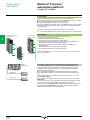
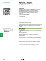
Hot Standby system
Unity™ Pro software
Functions
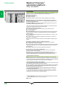
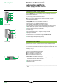
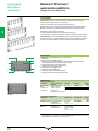
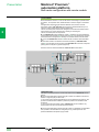
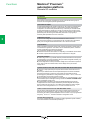
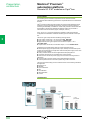
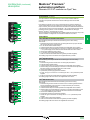
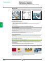
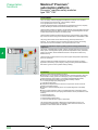
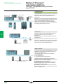
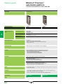
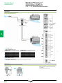
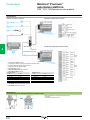
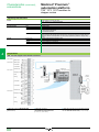
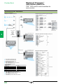
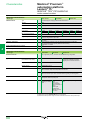
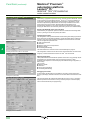
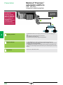
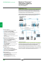
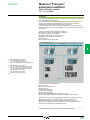
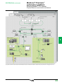
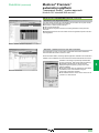
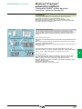
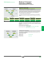
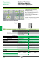
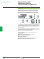
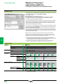
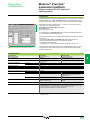
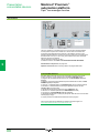
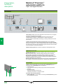
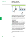
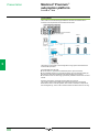
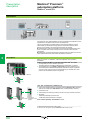
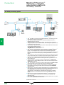
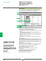
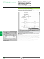
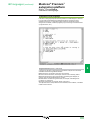
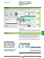
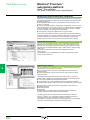
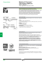
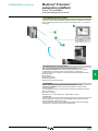
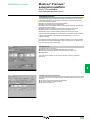
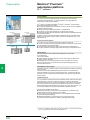
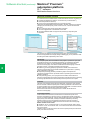
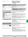
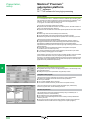
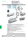
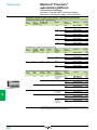
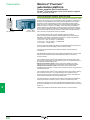
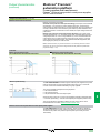
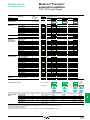
Functions of “Primary” and “Standby” PLCs
1
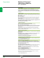
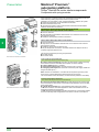
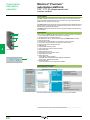
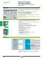
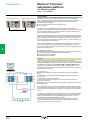
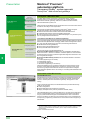
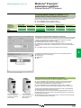
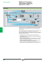
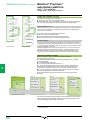
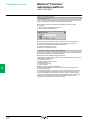
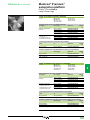
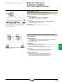
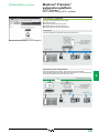
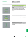
“Primary” and “Standby” PLCs are physically and functionally identical; the
difference in their roles lies in their status (“Primary” or “Standby”).
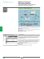
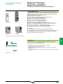
“Primary” Premium™ PLC
b Executes the entire application program
b Updates the inputs and outputs according to the in-rack architecture selected on
Bus X, Modbus® and/or Ethernet network
b Facilitates communication with peripheral devices
b Sends its data to the “Standby” PLC via the dedicated “CPU Sync” link and
retrieves diagnostic information from the “Standby” PLC.
b Generates its own diagnostic information as well as that of the Hot Standby
architecture
2
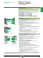
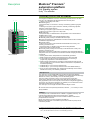
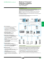
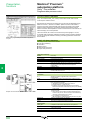
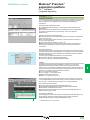
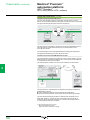
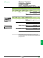
“Standby” Premium™ PLC
b Reads the state of the in-rack inputs on bus X of the “Standby” PLC
b Reads the image of the “Primary” PLC inputs (in-rack inputs on bus X, Modbus
and/or Ethernet)
b Executes the application in part (only the first section of the program)
b Updates the image of its outputs according to the execution of the first section of
the program
b Facilitates communication with peripheral devices
b Retrieves diagnostic information from the “Primary” PLC
b Generates its own diagnostic information as well as that of the Hot Standby
architecture
3
4
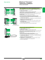
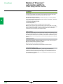
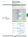
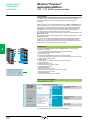
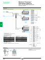
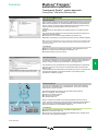
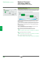
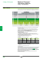
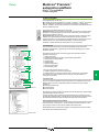
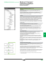
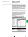
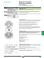
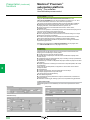
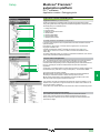
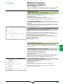
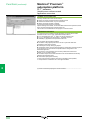
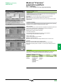
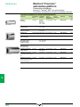
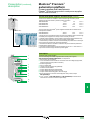
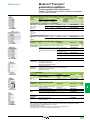
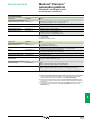
Management of “Primary/Standby” states
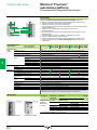
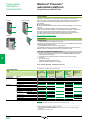
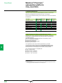
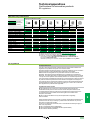
One of the following elements becoming inoperative:
v Main rack power supply
v PLC processor
The TSX™ ETY 4103/5103 “monitored” Ethernet Modbus/TCP network module
automatically triggers a “Primary/Standby” changeover. For all other elements,
“Primary/Standby” changeover can be customized via the application program
(manual changeover).
5
6
7
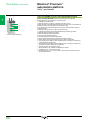
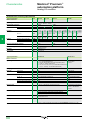
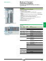
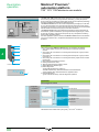
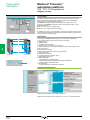
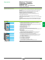
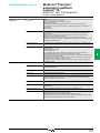
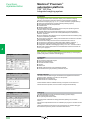
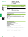
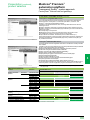
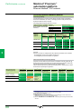
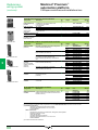
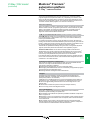
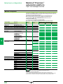
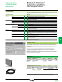
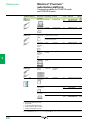
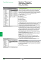
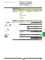
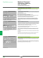
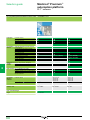
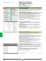
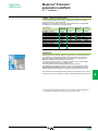
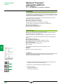
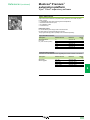
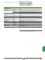
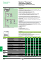
Services provided by TSX ETY 4103/5103 Ethernet
Modbus/TCP modules within the Hot Standby
architecture
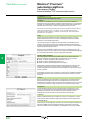
Standard Web: “Rack Viewer” and “Data Editor”
FactoryCast™ configurable Web (TSX ETY 5103 only)
User Web pages (8 MB with TSX ETY 5103)
Modbus®/TCP messaging
HTTP, FTP, XIP, Telnet
I/O Scanning
NTP time synchronization (with TSX ETY 5103)
SMTP e-mail notification (via Unity™ Pro function blocks)
Network manager, SNMP agent
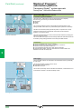
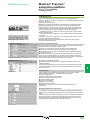
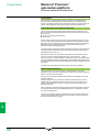
Management of shared I/O on Ethernet network
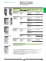
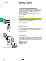
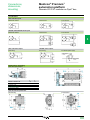
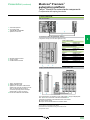
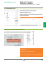
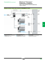
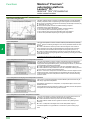
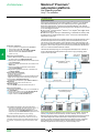
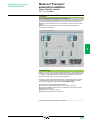
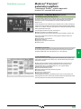
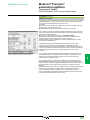
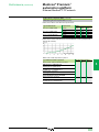
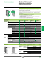
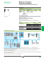
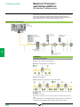
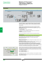
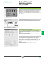
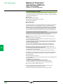
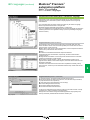
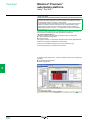
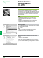
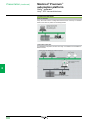
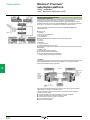
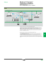
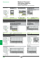
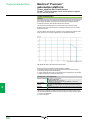
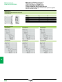
The “Primary” PLC can easily be configured to manage the exchange of shared
I/O states on the Ethernet network (bus or ring type). Thanks to the advanced
I/O Scanning service, there is no need for specific programming.
Only the “Primary” PLC reads the physical inputs on the network and controls the/
physical outputs on it.
During each cycle, the “Standby” PLC receives the images of the I/O on the Ethernet
network from the “Primary” PLC via the dedicated “CPU Sync” link. This updating of
the memory facilitates smooth “Primary/Standby” changeover during the
changeover time (devices or equipment maintaining their state on fallback).
Management of redundant I/O
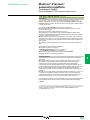
For redundant inputs, sensor information is transmitted simultaneously to the
“Primary” and “Standby” PLCs via the input module placed in the racks of each PLC.
The output values are generated solely by the application processing of the
“Primary” PLC, which sends its commands to the corresponding output modules.
During each cycle, the “Standby” PLC receives the “Primary” PLC output values via
the dedicated “CPU Sync” link and applies them to its own outputs.
This update method facilitates smooth “Primary/Standby” changeover during the
changeover time (outputs with fallback to 0).
8
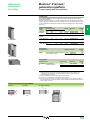
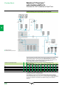
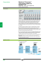
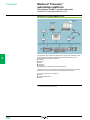
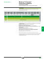
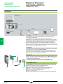
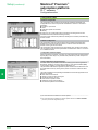
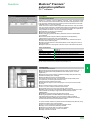
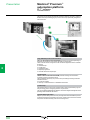
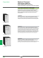
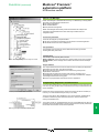
Management of supervision transparency (SCADA)
9
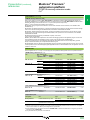
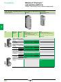
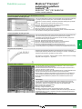
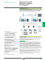
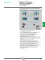
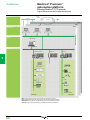
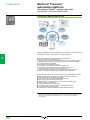
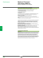
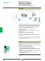
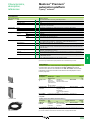
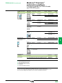
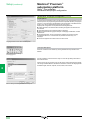
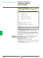
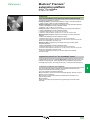
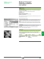
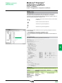
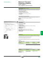
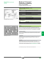
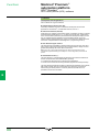
Another pair of TSX™ ETY 4103/5103 Ethernet Modbus/TCP modules helps to
ensure transparent communication with level 2 (supervisor, third-party device, etc)
during changeover of the PLC in “Primary” mode to the PLC in “Standby” mode.
Communication with a redundant architecture is, therefore, similar to that with a
standard architecture. This transparency is the result of the automatic mechanism
for the assignment of “IP” and “IP + 1” addresses.
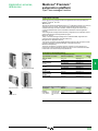
It can also be achieved on Modbus by using the TSX SCP 114 PCMCIA card
(Modbus slave protocol in RS 485) installed in the TSX SCY 21601 communication
module (automatic mechanism for the assignment of “n” and “n + 1” slave
addresses).
10
4/66