1
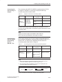
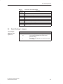
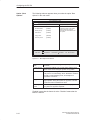
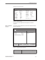
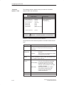
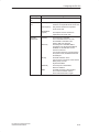
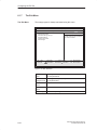
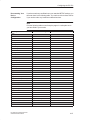
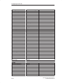
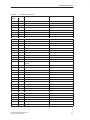
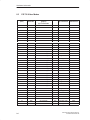
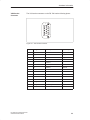
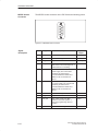
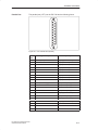
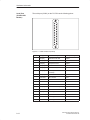
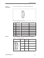
Hardware Information
8.2
Interrupt Assignments
Interrupt
Assignment
Priority
I/O Addresses of
the Interrupt
Controllers
The PG 720 uses the two integrated interrupt controllers of type 82C59
to handle the 16 hardware interrupts (IRQ 0 to IRQ 15).
The INT output of the slave controller is connected to the IRQ 2 input of
the master controller. Interrupt 9 (IRQ 9) can be used on the bus for the
assigned interrupt 2 (IRQ 2). In the initialization phase, IRQ 9 is assigned
to the software interrupt vector 0A H (IRQ 2) by the ROM-BIOS.
The priority of the interrupts is in the reverse order of their numbering. This
means the following: Interrupt IRQ 0 has the highest priority and interrupt
IRQ 7 the lowest. For triggering IRQ 2, interrupt IRQ 8 has the highest and
IRQ 15 the lowest priority. Interrupts IRQ 8 to IRQ 15 therefore have
higher priority than interrupts IRQ 3 to IRQ 7. The interrupt vectors are
initialized and masked when the PG 720 is powered up.
Interrupt
Description
Comment
Vector
SMI
System management interrupt, cannot
be masked
-
–
NMI
Expansion slots signal I/O channel
check 2
Fixed
INT 2 H
IRQ 0
Internal timer (system clock)
Fixed
INT 8 H
IRQ 1
Keyboard
Fixed
INT 9 H
IRQ 2
Cascading from interrupt controller 2
Fixed
INT A H
IRQ 3
Serial port 2 (COM2)
Can be
switched off *)
INT B H
IRQ 4
Serial interface 1 (COM1/TTY)
Can be
switched off *)
INT C H
IRQ 5
Sound, Cardbus controller SLOT 1
P&P **)
INT D H
IRQ 6
Floppy controller
Fixed
INT E H
IRQ 7
Parallel port 1 (printer port LPT 1/EPP/ Can be
ECP)
switched off *)
INT F H
IRQ 8
Battery-backed real-time clock (RTC)
Fixed
INT 70 H
IRQ 9
VGA controller
generally
vacant
INT 71 H
IRQ 10
Cardbus controller
Fixed
INT 72 H
IRQ 11
USB, Cardbus controller SLOT 2
Fixed
INT 73 H
IRQ 12
PS/2 mouse or trackball in keyboard
Can be
switched off *)
INT 74 H
IRQ 13
Math coprocessor error
Fixed
INT 75 H
IRQ 14
IDE interface (primary)
Fixed
INT 76 H
IRQ 15
IDE controller (secondary)
Fixed
INT 77 H
Note the interrupts which are already occupied in the system.
*)
These components can be disabled via the BIOS SETUP. The
functions are then no longer available and the resources are
released for other components.
**)
The on-board MPI/DP interface is plug&play-capable, the
occupied resources are managed by the BIOS.
PG 720 PII Programming Device
C79000-G7076-C756-02
8-5