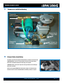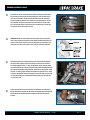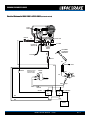
1
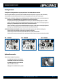
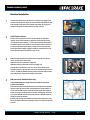
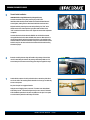
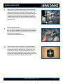
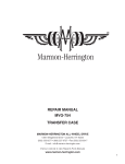
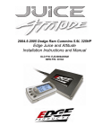
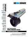
HIGH PERFORMANCE
PRXB EXHAUST BRAKE
C44060/C44062/C44064
APPLICATION:
1994-2002 DODGE RAM TRUCKS W/5.9L CUMMINS
DIESEL ENGINES WITH MANUAL SHIFT TRANSMISSIONS
C44060/C44062/C44064
Getting Started
Thank you and congratulations on your purchase of a Pacbrake exhaust retarder.
Before starting the installation, please read the entire installation manual carefully and be sure you have a full understanding
of the installation. Check that your Pacbrake kit is correct for the application and contains all the necessary parts.
NOTES: Pacbrake kit C44060 is a High Performance PRXB Exhaust Brake designed to provide maximum retarding throughout the
RPM range of your 1994-1998 Dodge 12 valve Cummins with a manual shift transmission.
Heavy Duty Exhaust Valve Springs ARE MANDATORY for all 12 valve engines, Pacbrake C14010 Spring Kit inc in C44060
Pacbrake kit C44062 is a High Performance PRXB Exhaust Brake designed to provide maximum retarding throughout the
RPM range of your 1998½ Dodge 24 valve Cummins with a manual shift transmission.
Pacbrake kit C44064 is a High Performance PRXB Exhaust Brake designed to provide maximum retarding throughout the
RPM range of your 1999-2002 Dodge 24 valve Cummins with a manual shift transmission.
ADDITIONAL MOUNTING GROUP REQUIRED: Vehicles with aftermarket exhaust systems require a different mounting group
Vehicles with 3" factory downpipe and HX 35 turbo, use Pacbrake Part #C11430
Vehicles with 4" aftermarket exhaust and 5 bolt HX 35 turbo outlet, use Pacbrake Part #C11431
Vehicles with 4" aftermarket exhaust and HX 40 or equivalent turbo with half marmon flange, use Pacbrake Part #C11432
Kit - C44060
Kit - C44062
Kit - C44064
Optional Accessories
Shifter Switches for Manual Transmissions
Use C18041 lighted switch for M/Y 1999-2002
and 1988-1993 with 5/8 OD shift lever diameter
Use C18040 lighted switch for M/Y 1994-1998
with 3/4 OD shift lever diameter
ECM Bypass Kit for 1999-2002 vehicles, C12015
I N STA L L AT I O N M A N U A L - L5822
PG. 2
C44060/C44062/C44064
Electrical Installation
1
Locate the main wiring harness supplied in the kit. Using the self tapping screws
provided, mount the harness relays on the driver side fender well between the ABS
brake controller and the fuse panel. Install both relays. Route the orange wire of
the harness through the fire wall grommet to the inside of the cab.
2
ON/OFF Switch Installation:
3
Provided on the last pages of this manual are two templates for dash switch
locations. The two switch locations are suggestions. Consult with the customer
for their preference before drilling a 1/2" hole to accommodate the switch. Manual
transmission vehicles can use a shift lever mounted control switch for the driver’s
convenience. 1994-1998½ models require an orange wire to be connected to the
control switch before installing (supplied in C14004 kit). Connect the wires to the
control switch as shown in the schematic on page 9 or 10.
Remove the dash panel below the steering column. At the base of the steering
column, locate an ignition power supply.
1994-1997 models use a medium blue 14 gage wire
1998-2002 models use a black with orange tracer 18 gage wire
Check the wire with a voltmeter to ensure it is 12 volts and an ignition source.
Attach the supplied “T” tap to this wire and insert the supplied 16 gauge fused wire
to this “T” tap. With the additional harness provided, connect the switch as shown
in the wiring diagram on page 8 or 9. Install the control switch.
4
ECM Connection for 1999-2002 Vehicles Only:
If using C12015 ECM Bypass, disregard this step and follow the instructions
provided in the C12015 kit.
Disconnect both positive battery leads. Remove the two capscrews that attach the
fuel filter head to the intake manifold. This should allow for enough clearance to
access the 50 pin ECM connector. Locate PIN 20 and remove the sealing plug. Be
careful not to push the sealing pin into the connector. If this happens, use an Allen
key to remove the ECM connector from the ECM, and use a small pick to push the
sealing pin out from the backside.
Route the black wire with special ECM Pin to the ECM. Insert the black wire of the
harness into PIN 20 until it stops. Pull gently to make sure it is locked into the ECM
connector.
I N STA L L AT I O N M A N U A L - L5822
PG. 3
C44060/C44062/C44064
5
Throttle Switch Installation:
1999-2002 Vehicles using ECM Connection, disregard this step.
Locate the stud shown in the photo pertaining to your M/Y truck.
Install the switch assembly with the switch arm horizontal. Reinstall the stud
nut and tighten, making sure the switch arm is behind the accelerator lever.
Adjust the switch by loosening the screws and positioning it to “click” as the
throttle returns to its released position. Cycle the throttle and listen for the
“click” each time the throttle returns to idle. Tighten the screws when adjustment
is complete.
Locate the black wire with the Cummins ECM PIN. Cut off this PIN and attach
the supplied black wire with a heat shrinkable butt connector. Route this wire in
the cab through the fire wall to the throttle switch. Crimp on the supplied spade
terminal connected to the diode. Attach the orange wire (connected to the control
switch in step 2) to the other terminal on the throttle switch. Consult the wiring
schematic on page 9.
6
Route the remaining harness along the firewall to the passenger side and then
route it forward along the fender to the passenger side battery. Make sure it is
secured away from heat sources and moving parts using the supplied tie-straps.
7
Consult with the customer for their preferred location to mount the quick disconnect for the airline. The mounting location should be in a clean, dry area with easy
access to the operator.
See photo in step 8 for a suggested location.
Using the two self tapping screws, mount the “L” bracket. Insert the bulkhead
airline fitting into the “L” bracket and tighten the jam nut to secure it. Follow the
airline installation procedures in the next step. Make sure the nylon is cut square
on each end and is pushed into the fittings until it clicks.
I N STA L L AT I O N M A N U A L - L5822
PG. 4
C44060/C44062/C44064
8
Shown in the photo is a suggested location marked “A”. Connect one end of the
remaining air line into the quick connect assembly and route this to the remaining
fitting at the compressor. Mount the air inlet filter in a cool, dry location. A suggested location is shown in photo, marked with a “B”. Locate the blue nylon airline
provided and route to the filter housing. Route the other end to the compressor
inlet fitting located on the compressor body (the compressor is installed in next
step). Make sure the nylon hose is cut square on each end and is pushed into the
fittings until it clicks.
A
B
9
Remove the passenger side battery.
Place the compressor and bracket assembly into the battery box as shown in the
photo. Place and secure the battery on top of the compressor bracket. Reinstall the
hold down assembly. Connect the corresponding weather pac connectors of the
Pacbrake harness to the compressor.
Do not connect the battery cables at this time.
10
Install the 90° fitting in the top of the tank and the provided hex plug (or drain
valve if desired) into the bottom, as shown in the photo. Use thread sealant on all
fittings to prevent air leaks. The air tank requires 2 - 5/16" holes on a 3¼" center.
For fastening to the frame, use one of the pre-existing holes in the frame and
drill the second hole. Using the fasteners provided, mount the air tank on the outside of the frame. Connect the nylon airline to the air tank and route the other end
to the fitting at the solenoid (shown in the photo below) and connect. I N STA L L AT I O N M A N U A L - L5822
PG. 5
C44060/C44062/C44064
11
Compressor and Airline Routing
Connect to
quick connect
Connect to air
intake filter
Connect to
air tank
Connect to
exhaust brake
12
Exhaust Brake Installation
All vehicles, remove the two capscrews that attaches the cast elbow to the header pipe.
1994-1998 vehicles, remove the V clamp between the elbow and the turbo charger.
Remove the cast elbow. Removal of the 5 bolt flange is not required.
1999-2002 vehicles, remove the 5 capscrews securing the elbow to the turbocharger. Remove the cast elbow.
NOTE: 12 valve engines REQUIRE H.D. exhaust valve springs to be installed. Contact Pacbrake Customer Service @ 800.663.0096 for installation procedure, if required.
I N STA L L AT I O N M A N U A L - L5822
PG. 6
C44060/C44062/C44064
13
From below the vehicle, remove the header pipe by removing the exhaust clamp
at the header pipe connection to the intermediate pipe. Once the header pipe is
removed from the vehicle, loosely install the elbow back onto the header pipe.
Loosely assemble the Pacbrake to the adapters for measuring purposes. Lay the
two assemblies side by side to determine the correct location to cut the header
pipe. The Pacbrake adapter is expanded to fit over the header pipe, consider this
in your measurement. Cut the pipe to length.
14
1999-2002 vehicles, at the turbocharger check the gasket surface for imperfections. If okay, install the new gasket and turbo flange provided. Replace the 5 capscrews removed earlier. Torque the capscrews to 110 in-lbs in a star pattern, then
retorque to 220 in-lbs in a star pattern. After a road test, retorque to 220 in-lbs.
in-lbs
in-lbs
15
Install the Pacbrake as an assembly (exhaust brake and both exhaust adapters).
The exhaust brake cylinder must be on the bottom to attain correct clearances.
Do not fully tighten the turbo “V” clamp, as adjustment may be necessary. Install
the shortened header pipe into the rear Pacbrake flange and intermediate exhaust
pipe. Adjust the assembly to attain maximum clearance and a good pipe fit. Torque
the turbo “V” clamp to 6 ft-lbs and then the exhaust brake pressure side “V” clamp
to 12 ft-lbs. Tack weld the rear Pacbrake adapter to the header pipe and remove the
“V” clamp and header pipe for welding. Reinstall the header pipe and torque the
“V” clamp to 12 ft-lbs.
16
Connect the nylon air line from the solenoid valve installed in step 7. Reconnect
both positive battery terminals and the positive and negative leads of the Pacbrake
harness. Secure all electrical harnesses and nylon air lines with the tie straps
provided.
I N STA L L AT I O N M A N U A L - L5822
PG. 7
C44060/C44062/C44064
Testing the System
Turn the ignition to ON and the Pacbrake switch ON. Do not start the vehicle yet. The compressor should start pumping air, filling the air tank.
Once maximum pressure is achieved the compressor should shut off. Wait for 2 minutes listening for the compressor to start up. If the compressor cycles then an air leak is present and must be repaired.
Start the vehicle and allow to idle with the Pacbrake applied. Lightly depress the accelerator pedal and the exhaust brake should release. If not,
adjust the throttle switch so the exhaust brake is disabled with light throttle pressure.
To check for exhaust leaks, idle the vehicle with the exhaust brake applied and before the engine gets hot, feel around all the exhaust connections for leaks. Repair as necessary.
Road test the vehicle attaining high engine RPM and apply the exhaust brake several times to ensure that it applies and releases quickly.
Congratulations, you have completed the installation.
I N STA L L AT I O N M A N U A L - L5822
PG. 8
C44060/C44062/C44064
Electrical Schematic: 1994-1998½ & 1999-2002 (w/throttle switch)
TO QUICK
CONNECT
PRESSURE
SWITCH
CONNECTOR
AIR INLET FILTER
Red
Black
TO CYLINDER
TO BATTERY
(NEGATIVE)
PACBRAKE
SOLENOID
Blue
Blue
TO AIR TANK
T-TAP TERMINAL
1 2 V IGNITION-ON
POWER SOURCE
FU
SE
CONNECTOR
Red
CONNECTOR
NOTE: Black wire must
be attached to same
terminal as the diode
Ground
Black
Red
THROTTLE
SWITCH
Black
Red
DASH
SWITCH
Orange
Black
Orange
CONNECTOR
30
SOL RELAY
87
Red/White Tracer
#1
86
86
85
87
#2
30
COMP RELAY
Red
85
Black
Black
Black
+
BATTERY
I N S TA L L AT I O N M A N U A L
- L5913
I N STA L L AT I O N M A N U A L - L5822
PG. 10
PG. 9
C44060/C44062/C44064
Electrical Schematic: 1999-2002
To Quick
Connect
Pressure
Switch
Red
Connector
Air Inlet Port
Black
Pacbrake
Solenoid
Blue
Blue
To Air Tank
Red
Red White Tracer
To
Cylinder
To Battery
(negative)
T-TAP TERMINAL
1 2 V IGNITION-ON
POWER SOURCE
Connector
87
85
Black
#2
30
FU
SE
COMP RELAY
86
Red
Black
Red
Black
87
85
SOL RELAY
#1
Ground
Black
86
30
Red
DASH
SWITCH
+
Firewall
BATTERY
Orange
PIN 20
Using the plastic ties supplied, secure the PACBRAKE harness
to the Dodge main harness. Be sure to follow DRIP LOOP in the
Dodge harness when securing the PACBRAKE harness.
DRIP LOOP
NOTE: Vehicle ECM has a 3 second delay in activating the exhaust brake
To eliminate the 3 second delay, use ECM Bypass Kit C12015
I N STA L L AT I O N M A N U A L - L5822
PG. 10
*Pacbrake exhaust brakes are protected by law U.S. patents 5,445,248. Patents pending. Pacbrake is a registered trademark of Pacbrake Company.
Other trademarks used herein are property of their respective holders.
Printed in Canada L5822_REV3.07.04.2011
Dash Switch Template:
1994-1998
DODGE
RAM
DASH SW ITCH TEMPLATE
MODEL YEARS 1994-1998
1/2" Drill
Flush with edge of panel
Hood release handle cut-out
Cut out template along outer edge and align as shown.
Flush with center of screw hole
Dash Switch Template:
1999-2002
Align with bottom of dash bezel
Cigarette Lighter
Cut out template along outer edge and align as shown.
NOTE: Template location is
only a suggestion. Access
to back of this location is
difficult and wires must be
installed on switch terminals
prior to installation.
Align with bottom of dash bezel
1/2" Drill
* Alternate Location
At Bottom Of Page
Cigarette Lighter
Cut out template along outer edge and align as shown.
NOTE: Template location is
only a suggestion. Access
to back of this location is
difficult and wires must be
installed on switch terminals
prior to installation.
Flush with edge of panel
1/2" Drill