1
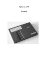
DigiMaster
Intelligent Auto ECU Data Processor
Iron must be grounded securely, can choose inner heating 20w iron or outer heating 25w iron if
constant temperature iron is not available. The max power of inner heating iron is 25w and 30w for
outer heating one.
b. Selection of flux
Rosin is one of the selection. It’s not allowed to use flux paste which with strong causticity. The
rosin must be replaced when it becomes carbonized black.
For solder it’s a must to select imported solder wire with low melt point and contains flux inside.
2).Dismounting of
IC
a.To dismount DIP IC: use solder sucker or solder absorbing weave to remove all the solder on
the pins of the IC. Don’t try to pull off by force.
b.To dismount SOP IC: applies ample of flux and
solder on each pin,
then heats the 2 rows of
the pins alternately until the IC is free from the board and then remove the IC away from the
board. Don’t try to unclench the IC.
c.Don’t heat excessively in case of damage the IC.
d.The IC on instrument is usually protected by lacquer coating. Before dismounting should heat the
coat and then remove it with blade or tweezers.
e. How to remove the lacquer coat from PCB or IC?
To remove the lacquer on PCB, uses an iron or hot blower to heat the lacquer up to 70–80
centigrade, then strips the coating with one slot screw driver, then start soldering when the
coating is removed.
3).Soldering of IC
a. Control soldering time not excessive in case of burn the IC.
b. Iron will be oxidized under high temperature for a long time and it is liable not to attach the
solder easily. Then rub the iron tip with wet cloth or sponge to clean it.
c. The heat should be conducted by solder, it is helpless to place the iron tip on IC pin.
d. Don’t move the IC before the solder solidify.
e. Firstly, solder the 2 pins which are on the diagonal to locate the IC, verify if the IC position
properly, then solder the rests.
How to identify the pin on IC
1). If there is a notch on IC, then placement as the illustration, the pin at lowest left is pin 1, and the
follows are pin 2, 3, 4, 5, 6, 7, 8 in anticlockwise.
2). If there is no notch but a spot on IC, then placement as the illustration, the pin near the spot is pin
1, and the follows are the same as the statement above.
3). If there is only text but no notch nor spot on IC, then placement as the illustration in the correct
direction that you can read the text properly, the pin at lowest left is pin 1, and the follows are the
same as the statement above.
ZhuHai QiChuang ELEC TECH CO., LTD
Website:http://www.qcet.cn
6
TEL: +86-756-2162500 , 2162501
FAX: +86-756-2162515