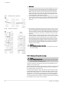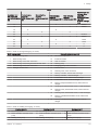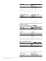
1
United Kingdom
en
Installation operation and maintenance manual
Condensing gas boiler
Eurocondense four
125 kW
170 kW
215 kW
260 kW
300 kW
Dear Customer,
Thank you very much for buying this appliance.
Please read through the manual carefully before using the product, and keep it in a safe place for later reference.
In order to ensure continued safe and efficient operation we recommend that the product is serviced regularly. Our service and
customer service organisation can assist with this.
We hope you enjoy years of problem-free operation with the product.
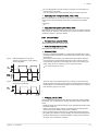
Contents
Contents
1 Safety . . . . . . . . . . . . . . . . . . . . . . . . . . . . . . . . . . . . . . . . . . . . . . . . . . . . . . . . . . . . . . . . . . . . . . . . . . 6
1.1 General safety instructions . . . . . . . . . . . . . . . . . . . . . . . . . . . . . . . . . . . . . . . . . . . . . . . . . . . . . . 6
1.2 Intended use . . . . . . . . . . . . . . . . . . . . . . . . . . . . . . . . . . . . . . . . . . . . . . . . . . . . . . . . . . . . . . . . . 8
1.3 Specific safety instructions . . . . . . . . . . . . . . . . . . . . . . . . . . . . . . . . . . . . . . . . . . . . . . . . . . . . . . 8
1.3.1 Liquid gas below ground level . . . . . . . . . . . . . . . . . . . . . . . . . . . . . . . . . . . . . . . . . . . . . 8
1.4 Liabilities . . . . . . . . . . . . . . . . . . . . . . . . . . . . . . . . . . . . . . . . . . . . . . . . . . . . . . . . . . . . . . . . . . . . 8
1.4.1 Manufacturer's liability . . . . . . . . . . . . . . . . . . . . . . . . . . . . . . . . . . . . . . . . . . . . . . . . . . . 8
1.4.2 Installer's liability . . . . . . . . . . . . . . . . . . . . . . . . . . . . . . . . . . . . . . . . . . . . . . . . . . . . . . . .9
1.4.3 User's liability . . . . . . . . . . . . . . . . . . . . . . . . . . . . . . . . . . . . . . . . . . . . . . . . . . . . . . . . . . 9
2
About this manual . . . . . . . . . . . . . . . . . . . . . . . . . . . . . . . . . . . . . . . . . . . . . . . . . . . . . . . . . . . . . . . . . . . . . . . . . . . . . . . . . . 10
2.1 General . . . . . . . . . . . . . . . . . . . . . . . . . . . . . . . . . . . . . . . . . . . . . . . . . . . . . . . . . . . . . . . . . . . . . . . . . . . . . . . . . . . . . 10
2.2 Additional documentation . . . . . . . . . . . . . . . . . . . . . . . . . . . . . . . . . . . . . . . . . . . . . . . . . . . . . . . . . . . . . . . . . . . . . . . 10
2.3 Symbols used . . . . . . . . . . . . . . . . . . . . . . . . . . . . . . . . . . . . . . . . . . . . . . . . . . . . . . . . . . . . . . . . . . . . . . . . . . . . . . . . 10
2.3.1
Symbols used in the manual . . . . . . . . . . . . . . . . . . . . . . . . . . . . . . . . . . . . . . . . . . . . . . . . . . . . . . . . . . . . . 10
3
Technical specifications . . . . . . . . . . . . . . . . . . . . . . . . . . . . . . . . . . . . . . . . . . . . . . . . . . . . . . . . . . . . . . . . . . . . . . . . . . . . . 12
3.1 Homologations . . . . . . . . . . . . . . . . . . . . . . . . . . . . . . . . . . . . . . . . . . . . . . . . . . . . . . . . . . . . . . . . . . . . . . . . . . . . . . . 12
3.1.1
Regulations and standards . . . . . . . . . . . . . . . . . . . . . . . . . . . . . . . . . . . . . . . . . . . . . . . . . . . . . . . . . . . . . . 12
3.1.2
Manufacturer’s Declaration . . . . . . . . . . . . . . . . . . . . . . . . . . . . . . . . . . . . . . . . . . . . . . . . . . . . . . . . . . . . . . 12
3.2 Technical data . . . . . . . . . . . . . . . . . . . . . . . . . . . . . . . . . . . . . . . . . . . . . . . . . . . . . . . . . . . . . . . . . . . . . . . . . . . . . . . .12
3.2.1
Technical data – Boiler space heaters in accordance with ErP guideline . . . . . . . . . . . . . . . . . . . . . . . . . . . 12
3.2.2
Technical data . . . . . . . . . . . . . . . . . . . . . . . . . . . . . . . . . . . . . . . . . . . . . . . . . . . . . . . . . . . . . . . . . . . . . . . . 13
3.2.3
Tables of sensor values . . . . . . . . . . . . . . . . . . . . . . . . . . . . . . . . . . . . . . . . . . . . . . . . . . . . . . . . . . . . . . . . .15
3.2.4
Pressure drop secondary circuit . . . . . . . . . . . . . . . . . . . . . . . . . . . . . . . . . . . . . . . . . . . . . . . . . . . . . . . . . . 16
3.2.5
Dimensions and connections . . . . . . . . . . . . . . . . . . . . . . . . . . . . . . . . . . . . . . . . . . . . . . . . . . . . . . . . . . . . .17
3.2.6
Wiring diagram . . . . . . . . . . . . . . . . . . . . . . . . . . . . . . . . . . . . . . . . . . . . . . . . . . . . . . . . . . . . . . . . . . . . . . . .19
4
Description of the product . . . . . . . . . . . . . . . . . . . . . . . . . . . . . . . . . . . . . . . . . . . . . . . . . . . . . . . . . . . . . . . . . . . . . . . . . . . . 20
4.1 Main components . . . . . . . . . . . . . . . . . . . . . . . . . . . . . . . . . . . . . . . . . . . . . . . . . . . . . . . . . . . . . . . . . . . . . . . . . . . . . 20
4.1.1
Boiler . . . . . . . . . . . . . . . . . . . . . . . . . . . . . . . . . . . . . . . . . . . . . . . . . . . . . . . . . . . . . . . . . . . . . . . . . . . . . . . 20
4.1.2
Room device RGT . . . . . . . . . . . . . . . . . . . . . . . . . . . . . . . . . . . . . . . . . . . . . . . . . . . . . . . . . . . . . . . . . . . . . 21
4.2 Control panel description . . . . . . . . . . . . . . . . . . . . . . . . . . . . . . . . . . . . . . . . . . . . . . . . . . . . . . . . . . . . . . . . . . . . . . . 21
4.2.1
Operating elements . . . . . . . . . . . . . . . . . . . . . . . . . . . . . . . . . . . . . . . . . . . . . . . . . . . . . . . . . . . . . . . . . . . . 21
4.2.2
Displays . . . . . . . . . . . . . . . . . . . . . . . . . . . . . . . . . . . . . . . . . . . . . . . . . . . . . . . . . . . . . . . . . . . . . . . . . . . . . 22
4.3 Accessories and options . . . . . . . . . . . . . . . . . . . . . . . . . . . . . . . . . . . . . . . . . . . . . . . . . . . . . . . . . . . . . . . . . . . . . . . . 22
4.3.1
Accessories . . . . . . . . . . . . . . . . . . . . . . . . . . . . . . . . . . . . . . . . . . . . . . . . . . . . . . . . . . . . . . . . . . . . . . . . . . 22
4.3.2
Installation of extension modules . . . . . . . . . . . . . . . . . . . . . . . . . . . . . . . . . . . . . . . . . . . . . . . . . . . . . . . . . .22
5
Before installation . . . . . . . . . . . . . . . . . . . . . . . . . . . . . . . . . . . . . . . . . . . . . . . . . . . . . . . . . . . . . . . . . . . . . . . . . . . . . . . . . . 23
5.1 Regulations governing installation . . . . . . . . . . . . . . . . . . . . . . . . . . . . . . . . . . . . . . . . . . . . . . . . . . . . . . . . . . . . . . . . 23
5.2 Installation requirements . . . . . . . . . . . . . . . . . . . . . . . . . . . . . . . . . . . . . . . . . . . . . . . . . . . . . . . . . . . . . . . . . . . . . . . . 23
5.2.1
Corrosion protection . . . . . . . . . . . . . . . . . . . . . . . . . . . . . . . . . . . . . . . . . . . . . . . . . . . . . . . . . . . . . . . . . . . 23
5.2.2
Supply air openings . . . . . . . . . . . . . . . . . . . . . . . . . . . . . . . . . . . . . . . . . . . . . . . . . . . . . . . . . . . . . . . . . . . . 23
5.2.3
Heating water requirements . . . . . . . . . . . . . . . . . . . . . . . . . . . . . . . . . . . . . . . . . . . . . . . . . . . . . . . . . . . . . .24
5.2.4
Further information on the heating water . . . . . . . . . . . . . . . . . . . . . . . . . . . . . . . . . . . . . . . . . . . . . . . . . . . .24
5.2.5
Diagram of water hardness . . . . . . . . . . . . . . . . . . . . . . . . . . . . . . . . . . . . . . . . . . . . . . . . . . . . . . . . . . . . . . 25
5.2.6
Treating and preparing the heating water . . . . . . . . . . . . . . . . . . . . . . . . . . . . . . . . . . . . . . . . . . . . . . . . . . . 25
5.2.7
Water hardness tips . . . . . . . . . . . . . . . . . . . . . . . . . . . . . . . . . . . . . . . . . . . . . . . . . . . . . . . . . . . . . . . . . . . 27
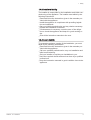
5.3 Choice of the location . . . . . . . . . . . . . . . . . . . . . . . . . . . . . . . . . . . . . . . . . . . . . . . . . . . . . . . . . . . . . . . . . . . . . . . . . . 28
5.3.1
Notes for installation location . . . . . . . . . . . . . . . . . . . . . . . . . . . . . . . . . . . . . . . . . . . . . . . . . . . . . . . . . . . . .28
5.3.2
Space requirement . . . . . . . . . . . . . . . . . . . . . . . . . . . . . . . . . . . . . . . . . . . . . . . . . . . . . . . . . . . . . . . . . . . . 29
5.4 Transport . . . . . . . . . . . . . . . . . . . . . . . . . . . . . . . . . . . . . . . . . . . . . . . . . . . . . . . . . . . . . . . . . . . . . . . . . . . . . . . . . . . .29
5.5 Connecting diagrams . . . . . . . . . . . . . . . . . . . . . . . . . . . . . . . . . . . . . . . . . . . . . . . . . . . . . . . . . . . . . . . . . . . . . . . . . . 30
5.5.1
Application examples . . . . . . . . . . . . . . . . . . . . . . . . . . . . . . . . . . . . . . . . . . . . . . . . . . . . . . . . . . . . . . . . . . .30
5.5.2
Legend . . . . . . . . . . . . . . . . . . . . . . . . . . . . . . . . . . . . . . . . . . . . . . . . . . . . . . . . . . . . . . . . . . . . . . . . . . . . . .39
6
Installation . . . . . . . . . . . . . . . . . . . . . . . . . . . . . . . . . . . . . . . . . . . . . . . . . . . . . . . . . . . . . . . . . . . . . . . . . . . . . . . . . . . . . . . . 41
6.1 Mounting . . . . . . . . . . . . . . . . . . . . . . . . . . . . . . . . . . . . . . . . . . . . . . . . . . . . . . . . . . . . . . . . . . . . . . . . . . . . . . . . . . . . 41
6.1.1
Converting the exhaust connection . . . . . . . . . . . . . . . . . . . . . . . . . . . . . . . . . . . . . . . . . . . . . . . . . . . . . . . . 41
6.1.2
Installing the air supply duct at the side . . . . . . . . . . . . . . . . . . . . . . . . . . . . . . . . . . . . . . . . . . . . . . . . . . . . .42
6.1.3
Installing the air supply duct at the rear . . . . . . . . . . . . . . . . . . . . . . . . . . . . . . . . . . . . . . . . . . . . . . . . . . . . . 42
7636047 - 02 - 24082015
3
Contents
6.2
6.3
6.4
6.5
6.6
Hydraulic connection . . . . . . . . . . . . . . . . . . . . . . . . . . . . . . . . . . . . . . . . . . . . . . . . . . . . . . . . . . . . . . . . . . . . . . . . . . .43
6.2.1
Connecting the heating circuit . . . . . . . . . . . . . . . . . . . . . . . . . . . . . . . . . . . . . . . . . . . . . . . . . . . . . . . . . . . . 43
6.2.2
Safety valve . . . . . . . . . . . . . . . . . . . . . . . . . . . . . . . . . . . . . . . . . . . . . . . . . . . . . . . . . . . . . . . . . . . . . . . . . . 43
6.2.3
Condensate connection . . . . . . . . . . . . . . . . . . . . . . . . . . . . . . . . . . . . . . . . . . . . . . . . . . . . . . . . . . . . . . . . . 43
Gas connection . . . . . . . . . . . . . . . . . . . . . . . . . . . . . . . . . . . . . . . . . . . . . . . . . . . . . . . . . . . . . . . . . . . . . . . . . . . . . . . 43
6.3.1
Gas connection . . . . . . . . . . . . . . . . . . . . . . . . . . . . . . . . . . . . . . . . . . . . . . . . . . . . . . . . . . . . . . . . . . . . . . . 43
6.3.2
Check tightness . . . . . . . . . . . . . . . . . . . . . . . . . . . . . . . . . . . . . . . . . . . . . . . . . . . . . . . . . . . . . . . . . . . . . . . 44
6.3.3
Venting the gas line . . . . . . . . . . . . . . . . . . . . . . . . . . . . . . . . . . . . . . . . . . . . . . . . . . . . . . . . . . . . . . . . . . . . 44
Air supply/flue gas connections . . . . . . . . . . . . . . . . . . . . . . . . . . . . . . . . . . . . . . . . . . . . . . . . . . . . . . . . . . . . . . . . . . 44
6.4.1
Flue gas connection . . . . . . . . . . . . . . . . . . . . . . . . . . . . . . . . . . . . . . . . . . . . . . . . . . . . . . . . . . . . . . . . . . . .44
6.4.2
Flue gas system . . . . . . . . . . . . . . . . . . . . . . . . . . . . . . . . . . . . . . . . . . . . . . . . . . . . . . . . . . . . . . . . . . . . . . .45
6.4.3
General information about the exhaust gas piping system . . . . . . . . . . . . . . . . . . . . . . . . . . . . . . . . . . . . . . 46
6.4.4
Chimneys already in use . . . . . . . . . . . . . . . . . . . . . . . . . . . . . . . . . . . . . . . . . . . . . . . . . . . . . . . . . . . . . . . . 47
6.4.5
Assembly of the flue gas system . . . . . . . . . . . . . . . . . . . . . . . . . . . . . . . . . . . . . . . . . . . . . . . . . . . . . . . . . . 47
6.4.6
Cleaning and inspection openings . . . . . . . . . . . . . . . . . . . . . . . . . . . . . . . . . . . . . . . . . . . . . . . . . . . . . . . . .48
Electrical connections . . . . . . . . . . . . . . . . . . . . . . . . . . . . . . . . . . . . . . . . . . . . . . . . . . . . . . . . . . . . . . . . . . . . . . . . . . 49
6.5.1
Electrical connection (general) . . . . . . . . . . . . . . . . . . . . . . . . . . . . . . . . . . . . . . . . . . . . . . . . . . . . . . . . . . . 49
6.5.2
Cable lengths . . . . . . . . . . . . . . . . . . . . . . . . . . . . . . . . . . . . . . . . . . . . . . . . . . . . . . . . . . . . . . . . . . . . . . . . .49
6.5.3
Strain reliefs . . . . . . . . . . . . . . . . . . . . . . . . . . . . . . . . . . . . . . . . . . . . . . . . . . . . . . . . . . . . . . . . . . . . . . . . . .49
6.5.4
Circulating pumps . . . . . . . . . . . . . . . . . . . . . . . . . . . . . . . . . . . . . . . . . . . . . . . . . . . . . . . . . . . . . . . . . . . . . 50
6.5.5
Appliance fuses . . . . . . . . . . . . . . . . . . . . . . . . . . . . . . . . . . . . . . . . . . . . . . . . . . . . . . . . . . . . . . . . . . . . . . . 50
6.5.6
Connect sensor / components . . . . . . . . . . . . . . . . . . . . . . . . . . . . . . . . . . . . . . . . . . . . . . . . . . . . . . . . . . . . 50
6.5.7
Replacing cables . . . . . . . . . . . . . . . . . . . . . . . . . . . . . . . . . . . . . . . . . . . . . . . . . . . . . . . . . . . . . . . . . . . . . . 50
6.5.8
Protection against contact . . . . . . . . . . . . . . . . . . . . . . . . . . . . . . . . . . . . . . . . . . . . . . . . . . . . . . . . . . . . . . . 50
Filling the system . . . . . . . . . . . . . . . . . . . . . . . . . . . . . . . . . . . . . . . . . . . . . . . . . . . . . . . . . . . . . . . . . . . . . . . . . . . . . 50
7
Commissioning . . . . . . . . . . . . . . . . . . . . . . . . . . . . . . . . . . . . . . . . . . . . . . . . . . . . . . . . . . . . . . . . . . . . . . . . . . . . . . . . . . . . 51
7.1 General . . . . . . . . . . . . . . . . . . . . . . . . . . . . . . . . . . . . . . . . . . . . . . . . . . . . . . . . . . . . . . . . . . . . . . . . . . . . . . . . . . . . . 51
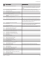
7.2 Checklist for commissioning . . . . . . . . . . . . . . . . . . . . . . . . . . . . . . . . . . . . . . . . . . . . . . . . . . . . . . . . . . . . . . . . . . . . . 51
7.3 Commissioning procedure . . . . . . . . . . . . . . . . . . . . . . . . . . . . . . . . . . . . . . . . . . . . . . . . . . . . . . . . . . . . . . . . . . . . . . 52
7.3.1
Commissioning menu . . . . . . . . . . . . . . . . . . . . . . . . . . . . . . . . . . . . . . . . . . . . . . . . . . . . . . . . . . . . . . . . . . 52
7.4 Gas settings . . . . . . . . . . . . . . . . . . . . . . . . . . . . . . . . . . . . . . . . . . . . . . . . . . . . . . . . . . . . . . . . . . . . . . . . . . . . . . . . . 52
7.4.1
Factory settings . . . . . . . . . . . . . . . . . . . . . . . . . . . . . . . . . . . . . . . . . . . . . . . . . . . . . . . . . . . . . . . . . . . . . . . 52
7.4.2
CO2 content . . . . . . . . . . . . . . . . . . . . . . . . . . . . . . . . . . . . . . . . . . . . . . . . . . . . . . . . . . . . . . . . . . . . . . . . . . 52
7.4.3
Changing over from natural gas to LPG and vice versa . . . . . . . . . . . . . . . . . . . . . . . . . . . . . . . . . . . . . . . . 52
7.4.4
Manual adjustment of burner output (controller stop function) . . . . . . . . . . . . . . . . . . . . . . . . . . . . . . . . . . . 53
7.4.5
Adjusting CO2 content . . . . . . . . . . . . . . . . . . . . . . . . . . . . . . . . . . . . . . . . . . . . . . . . . . . . . . . . . . . . . . . . . . 54
7.5 Final instructions . . . . . . . . . . . . . . . . . . . . . . . . . . . . . . . . . . . . . . . . . . . . . . . . . . . . . . . . . . . . . . . . . . . . . . . . . . . . . . 55
7.5.1
Instruction of the customer . . . . . . . . . . . . . . . . . . . . . . . . . . . . . . . . . . . . . . . . . . . . . . . . . . . . . . . . . . . . . . 55
7.5.2
Documents . . . . . . . . . . . . . . . . . . . . . . . . . . . . . . . . . . . . . . . . . . . . . . . . . . . . . . . . . . . . . . . . . . . . . . . . . . .55
8
Operation . . . . . . . . . . . . . . . . . . . . . . . . . . . . . . . . . . . . . . . . . . . . . . . . . . . . . . . . . . . . . . . . . . . . . . . . . . . . . . . . . . . . . . . . .56
8.1 Use of the control panel . . . . . . . . . . . . . . . . . . . . . . . . . . . . . . . . . . . . . . . . . . . . . . . . . . . . . . . . . . . . . . . . . . . . . . . . 56
8.1.1
Changing parameters . . . . . . . . . . . . . . . . . . . . . . . . . . . . . . . . . . . . . . . . . . . . . . . . . . . . . . . . . . . . . . . . . . 56
8.1.2
Programming procedure . . . . . . . . . . . . . . . . . . . . . . . . . . . . . . . . . . . . . . . . . . . . . . . . . . . . . . . . . . . . . . . . 56
8.2 Start-up . . . . . . . . . . . . . . . . . . . . . . . . . . . . . . . . . . . . . . . . . . . . . . . . . . . . . . . . . . . . . . . . . . . . . . . . . . . . . . . . . . . . . 57
8.2.1
Checking water pressure . . . . . . . . . . . . . . . . . . . . . . . . . . . . . . . . . . . . . . . . . . . . . . . . . . . . . . . . . . . . . . . . 57
8.2.2
Switching on . . . . . . . . . . . . . . . . . . . . . . . . . . . . . . . . . . . . . . . . . . . . . . . . . . . . . . . . . . . . . . . . . . . . . . . . . 57
8.2.3
Setting necessary parameters . . . . . . . . . . . . . . . . . . . . . . . . . . . . . . . . . . . . . . . . . . . . . . . . . . . . . . . . . . . . 58
8.2.4
Setting the heating mode . . . . . . . . . . . . . . . . . . . . . . . . . . . . . . . . . . . . . . . . . . . . . . . . . . . . . . . . . . . . . . . .58
8.2.5
Adjusting domestic water mode . . . . . . . . . . . . . . . . . . . . . . . . . . . . . . . . . . . . . . . . . . . . . . . . . . . . . . . . . . .59
8.2.6
Adjusting comfortable room setpoint . . . . . . . . . . . . . . . . . . . . . . . . . . . . . . . . . . . . . . . . . . . . . . . . . . . . . . . 59
8.2.7
Setting reduced room setpoint . . . . . . . . . . . . . . . . . . . . . . . . . . . . . . . . . . . . . . . . . . . . . . . . . . . . . . . . . . . .59
8.2.8
Emergency mode (Manual control) . . . . . . . . . . . . . . . . . . . . . . . . . . . . . . . . . . . . . . . . . . . . . . . . . . . . . . . . 59
8.2.9
Chimney sweep function . . . . . . . . . . . . . . . . . . . . . . . . . . . . . . . . . . . . . . . . . . . . . . . . . . . . . . . . . . . . . . . . 60
8.2.10 Restoring factory settings . . . . . . . . . . . . . . . . . . . . . . . . . . . . . . . . . . . . . . . . . . . . . . . . . . . . . . . . . . . . . . . 60
9
Settings . . . . . . . . . . . . . . . . . . . . . . . . . . . . . . . . . . . . . . . . . . . . . . . . . . . . . . . . . . . . . . . . . . . . . . . . . . . . . . . . . . . . . . . . . . 61
9.1 List of parameters . . . . . . . . . . . . . . . . . . . . . . . . . . . . . . . . . . . . . . . . . . . . . . . . . . . . . . . . . . . . . . . . . . . . . . . . . . . . . 61
9.2 Description of the parameters . . . . . . . . . . . . . . . . . . . . . . . . . . . . . . . . . . . . . . . . . . . . . . . . . . . . . . . . . . . . . . . . . . . . 83
9.2.1
Time and date . . . . . . . . . . . . . . . . . . . . . . . . . . . . . . . . . . . . . . . . . . . . . . . . . . . . . . . . . . . . . . . . . . . . . . . . 83
9.2.2
Operator section . . . . . . . . . . . . . . . . . . . . . . . . . . . . . . . . . . . . . . . . . . . . . . . . . . . . . . . . . . . . . . . . . . . . . . 83
9.2.3
Wireless . . . . . . . . . . . . . . . . . . . . . . . . . . . . . . . . . . . . . . . . . . . . . . . . . . . . . . . . . . . . . . . . . . . . . . . . . . . . . 84
9.2.4
Time programs . . . . . . . . . . . . . . . . . . . . . . . . . . . . . . . . . . . . . . . . . . . . . . . . . . . . . . . . . . . . . . . . . . . . . . . .85
9.2.5
Holiday programs . . . . . . . . . . . . . . . . . . . . . . . . . . . . . . . . . . . . . . . . . . . . . . . . . . . . . . . . . . . . . . . . . . . . . .85
9.2.6
Heating circuits . . . . . . . . . . . . . . . . . . . . . . . . . . . . . . . . . . . . . . . . . . . . . . . . . . . . . . . . . . . . . . . . . . . . . . . 86
4
7636047 - 02 - 24082015
Contents
9.2.7
9.2.8
9.2.9
9.2.10
9.2.11
9.2.12
9.2.13
9.2.14
9.2.15
9.2.16
9.2.17
9.2.18
9.2.19
9.2.20
9.2.21
9.2.22
9.2.23
9.2.24
9.2.25
9.2.26
Domestic water . . . . . . . . . . . . . . . . . . . . . . . . . . . . . . . . . . . . . . . . . . . . . . . . . . . . . . . . . . . . . . . . . . . . . . . 93
Consumer circuits/Swimming pool circuit . . . . . . . . . . . . . . . . . . . . . . . . . . . . . . . . . . . . . . . . . . . . . . . . . . . 95
Swimming pool . . . . . . . . . . . . . . . . . . . . . . . . . . . . . . . . . . . . . . . . . . . . . . . . . . . . . . . . . . . . . . . . . . . . . . . 95
Primary control/feed pump . . . . . . . . . . . . . . . . . . . . . . . . . . . . . . . . . . . . . . . . . . . . . . . . . . . . . . . . . . . . . . .95
Boiler . . . . . . . . . . . . . . . . . . . . . . . . . . . . . . . . . . . . . . . . . . . . . . . . . . . . . . . . . . . . . . . . . . . . . . . . . . . . . . . 96
Cascade . . . . . . . . . . . . . . . . . . . . . . . . . . . . . . . . . . . . . . . . . . . . . . . . . . . . . . . . . . . . . . . . . . . . . . . . . . . . .99
Solar . . . . . . . . . . . . . . . . . . . . . . . . . . . . . . . . . . . . . . . . . . . . . . . . . . . . . . . . . . . . . . . . . . . . . . . . . . . . . . 101
Solid fuel boiler . . . . . . . . . . . . . . . . . . . . . . . . . . . . . . . . . . . . . . . . . . . . . . . . . . . . . . . . . . . . . . . . . . . . . . 103
Buffer storage tank . . . . . . . . . . . . . . . . . . . . . . . . . . . . . . . . . . . . . . . . . . . . . . . . . . . . . . . . . . . . . . . . . . . 103
Drinking water storage . . . . . . . . . . . . . . . . . . . . . . . . . . . . . . . . . . . . . . . . . . . . . . . . . . . . . . . . . . . . . . . . .105
Configuration . . . . . . . . . . . . . . . . . . . . . . . . . . . . . . . . . . . . . . . . . . . . . . . . . . . . . . . . . . . . . . . . . . . . . . . . 109
LPB system . . . . . . . . . . . . . . . . . . . . . . . . . . . . . . . . . . . . . . . . . . . . . . . . . . . . . . . . . . . . . . . . . . . . . . . . . 116
Fault . . . . . . . . . . . . . . . . . . . . . . . . . . . . . . . . . . . . . . . . . . . . . . . . . . . . . . . . . . . . . . . . . . . . . . . . . . . . . . .117
Maintenance / special operation . . . . . . . . . . . . . . . . . . . . . . . . . . . . . . . . . . . . . . . . . . . . . . . . . . . . . . . . . 117
Configuration of extension modules . . . . . . . . . . . . . . . . . . . . . . . . . . . . . . . . . . . . . . . . . . . . . . . . . . . . . . 119
Input/output test . . . . . . . . . . . . . . . . . . . . . . . . . . . . . . . . . . . . . . . . . . . . . . . . . . . . . . . . . . . . . . . . . . . . . . 123
Status . . . . . . . . . . . . . . . . . . . . . . . . . . . . . . . . . . . . . . . . . . . . . . . . . . . . . . . . . . . . . . . . . . . . . . . . . . . . . .123
Diagnostics cascade/heat generation/consumers . . . . . . . . . . . . . . . . . . . . . . . . . . . . . . . . . . . . . . . . . . . . 128
Burner control . . . . . . . . . . . . . . . . . . . . . . . . . . . . . . . . . . . . . . . . . . . . . . . . . . . . . . . . . . . . . . . . . . . . . . . 128
Info option . . . . . . . . . . . . . . . . . . . . . . . . . . . . . . . . . . . . . . . . . . . . . . . . . . . . . . . . . . . . . . . . . . . . . . . . . . 129
10 Maintenance . . . . . . . . . . . . . . . . . . . . . . . . . . . . . . . . . . . . . . . . . . . . . . . . . . . . . . . . . . . . . . . . . . . . . . . . . . . . . . . . . . . . . 130
10.1 General . . . . . . . . . . . . . . . . . . . . . . . . . . . . . . . . . . . . . . . . . . . . . . . . . . . . . . . . . . . . . . . . . . . . . . . . . . . . . . . . . . . . 130
10.1.1 General instructions . . . . . . . . . . . . . . . . . . . . . . . . . . . . . . . . . . . . . . . . . . . . . . . . . . . . . . . . . . . . . . . . . . .130
10.1.2 Inspection and service as required . . . . . . . . . . . . . . . . . . . . . . . . . . . . . . . . . . . . . . . . . . . . . . . . . . . . . . . 130
10.2 Maintenance messages . . . . . . . . . . . . . . . . . . . . . . . . . . . . . . . . . . . . . . . . . . . . . . . . . . . . . . . . . . . . . . . . . . . . . . . 130
10.2.1 Maintenance message . . . . . . . . . . . . . . . . . . . . . . . . . . . . . . . . . . . . . . . . . . . . . . . . . . . . . . . . . . . . . . . . .130
10.2.2 Maintenance code table . . . . . . . . . . . . . . . . . . . . . . . . . . . . . . . . . . . . . . . . . . . . . . . . . . . . . . . . . . . . . . . .131
10.2.3 Operating phases of the Control Centre LMS . . . . . . . . . . . . . . . . . . . . . . . . . . . . . . . . . . . . . . . . . . . . . . . 131
10.3 Standard inspection and maintenance operations . . . . . . . . . . . . . . . . . . . . . . . . . . . . . . . . . . . . . . . . . . . . . . . . . . . 132
10.3.1 Checking water hardness . . . . . . . . . . . . . . . . . . . . . . . . . . . . . . . . . . . . . . . . . . . . . . . . . . . . . . . . . . . . . . 132
10.3.2 Removing the burner . . . . . . . . . . . . . . . . . . . . . . . . . . . . . . . . . . . . . . . . . . . . . . . . . . . . . . . . . . . . . . . . . . 132
10.3.3 Checking combustion room insulation . . . . . . . . . . . . . . . . . . . . . . . . . . . . . . . . . . . . . . . . . . . . . . . . . . . . . 133
10.3.4 Changing the combustion room insulation. . . . . . . . . . . . . . . . . . . . . . . . . . . . . . . . . . . . . . . . . . . . . . . . . . 133
10.3.5 Cleaning the burner pipe . . . . . . . . . . . . . . . . . . . . . . . . . . . . . . . . . . . . . . . . . . . . . . . . . . . . . . . . . . . . . . . 134
10.3.6 Cleaning the heat exchanger . . . . . . . . . . . . . . . . . . . . . . . . . . . . . . . . . . . . . . . . . . . . . . . . . . . . . . . . . . . .134
10.3.7 Cleaning the fan . . . . . . . . . . . . . . . . . . . . . . . . . . . . . . . . . . . . . . . . . . . . . . . . . . . . . . . . . . . . . . . . . . . . . .135
10.3.8 Changing the ignition electrodes . . . . . . . . . . . . . . . . . . . . . . . . . . . . . . . . . . . . . . . . . . . . . . . . . . . . . . . . . 135
10.3.9 Checking the ionization electrode . . . . . . . . . . . . . . . . . . . . . . . . . . . . . . . . . . . . . . . . . . . . . . . . . . . . . . . . 136
10.3.10 Changing the ionization electrode . . . . . . . . . . . . . . . . . . . . . . . . . . . . . . . . . . . . . . . . . . . . . . . . . . . . . . . . 136
10.3.11 Electrode spacing and installation locations . . . . . . . . . . . . . . . . . . . . . . . . . . . . . . . . . . . . . . . . . . . . . . . . 137
10.3.12 Protection against contact . . . . . . . . . . . . . . . . . . . . . . . . . . . . . . . . . . . . . . . . . . . . . . . . . . . . . . . . . . . . . . 137
10.4 Specific maintenance instructions . . . . . . . . . . . . . . . . . . . . . . . . . . . . . . . . . . . . . . . . . . . . . . . . . . . . . . . . . . . . . . . .137
10.4.1 Replacing the safety valve . . . . . . . . . . . . . . . . . . . . . . . . . . . . . . . . . . . . . . . . . . . . . . . . . . . . . . . . . . . . . .137
11 Troubleshooting . . . . . . . . . . . . . . . . . . . . . . . . . . . . . . . . . . . . . . . . . . . . . . . . . . . . . . . . . . . . . . . . . . . . . . . . . . . . . . . . . . .138
11.1 Fault code table . . . . . . . . . . . . . . . . . . . . . . . . . . . . . . . . . . . . . . . . . . . . . . . . . . . . . . . . . . . . . . . . . . . . . . . . . . . . . .138
11.2 Fault finding . . . . . . . . . . . . . . . . . . . . . . . . . . . . . . . . . . . . . . . . . . . . . . . . . . . . . . . . . . . . . . . . . . . . . . . . . . . . . . . . .140
11.2.1 Fault message . . . . . . . . . . . . . . . . . . . . . . . . . . . . . . . . . . . . . . . . . . . . . . . . . . . . . . . . . . . . . . . . . . . . . . 140
11.2.2 Fault switch-off . . . . . . . . . . . . . . . . . . . . . . . . . . . . . . . . . . . . . . . . . . . . . . . . . . . . . . . . . . . . . . . . . . . . . . .141
12 Disposal/recycling . . . . . . . . . . . . . . . . . . . . . . . . . . . . . . . . . . . . . . . . . . . . . . . . . . . . . . . . . . . . . . . . . . . . . . . . . . . . . . . . . 142
12.1 Packaging . . . . . . . . . . . . . . . . . . . . . . . . . . . . . . . . . . . . . . . . . . . . . . . . . . . . . . . . . . . . . . . . . . . . . . . . . . . . . . . . . . 142
12.2 Appliance disposal . . . . . . . . . . . . . . . . . . . . . . . . . . . . . . . . . . . . . . . . . . . . . . . . . . . . . . . . . . . . . . . . . . . . . . . . . . . 142
13 Appendix . . . . . . . . . . . . . . . . . . . . . . . . . . . . . . . . . . . . . . . . . . . . . . . . . . . . . . . . . . . . . . . . . . . . . . . . . . . . . . . . . . . . . . . . 143
13.1 Declaration of conformity . . . . . . . . . . . . . . . . . . . . . . . . . . . . . . . . . . . . . . . . . . . . . . . . . . . . . . . . . . . . . . . . . . . . . . 143
Index . . . . . . . . . . . . . . . . . . . . . . . . . . . . . . . . . . . . . . . . . . . . . . . . . . . . . . . . . . . . . . . . . . . . . . . . . . . . . . . . . . . . . . . . . . . 144
7636047 - 02 - 24082015
5
1 Safety
1 Safety
1.1 General safety instructions
Danger
If you smell gas:
1. Do not use a naked flame, do not smoke, do not
operate electrical contacts or switches (doorbell,
light, motor, lift, etc.).
2. Shut off the gas supply.
3. Open the windows.
4. Trace possible leaks and seal them immediately.
5. If the gas leak is before the gas meter, contact the
gas supplier.
Danger
Danger to life.
Observe the warnings affixed to the gas condensing
boiler. Incorrect operation of the gas condensing boil
er can lead to considerable damage.
Danger
Danger to life.
Commissioning, settings, maintenance and cleaning
of gas condensing boilers may only be carried out by
a qualified installer.
Danger of electric shock
Danger to life due to improper work.
All electrical work in connection with the installation
may only be carried out by a trained electrician.
Danger
Risk of poisoning.
Never use water from the heating system as drinking
water. It is contaminated by deposits.
Caution
Danger of freezing!
If there is a danger of freezing do not shut down the
heating system; continue to operate it at least in econ
omy mode with radiator valves open. You should only
shut down the heating system and drain the boiler, do
mestic water storage tank and radiators if it is not pos
sible to heat in frost mode.
Caution
Secure against unintentional switch-on.
When the heating system is empty, ensure that the
boiler cannot be switched on unintentionally.
6
7636047 - 02 - 24082015
1 Safety
Danger
This appliance can be used by children aged 8 years
and above and by persons with reduced physical,
sensory or mental capabilities or lack of experience
and knowledge when they have been given supervi
sion or instruction concerning the safe use of the de
vice and understand the resulting risks. Children must
not be allowed to play with the appliance. Cleaning
and user maintenance must not be carried out by chil
dren without supervision.
Danger
The heating system must not continue to be operated
if damaged.
Danger
Danger! Danger to life through modifications to the ap
pliance.
Unauthorised conversions and modifications to the
gas appliance are not permitted, as this can endanger
persons and cause damage to the appliance. The ap
pliance approval will become void if these instructions
are not observed.
Caution
Replacement of damaged parts may only be per
formed by an installer.
Caution
Connections sealed with thread sealant must never be
opened or modified by a non-specialist. The seals
serve as proof that essential connections for safe,
trouble-free operation have not been tampered with.
The guarantee becomes void if the seals are dam
aged.
Warning
Risk of damage.
The gas condensing boiler may only be installed in
rooms with clean combustion air. Foreign matter such
as pollen must never filter through the inlet apertures
to reach the inside of the appliance. The boiler must
not be started up if there is heavy dust development
e.g. during construction work. There could be damage
to the boiler.
Caution
Keep the inflow area clear.
Never block or close off ventilation apertures. The in
flow area for combustion air must be kept clear.
7636047 - 02 - 24082015
7
1 Safety
Danger
Danger to life due to explosion/fire.
Do not store any explosive or easily flammable materi
als close to the appliance.
Caution
Risk of burns!
For safety reasons, the discharge pipe from the safety
valve must always be open so that water can escape
during heating operation. The operating state of the
safety valve must be checked from time to time.
1.2 Intended use
The gas condensing boilers of the EC four series are inten
ded to be used according to DIN EN 12828 as heat genera
tors in domestic water heating systems.
They conform to DIN EN 676, DIN 4702 Part 6 and DIN EN
677, installation type B23, C33, C53, C63x and C83.
See
In case of the installation types C33, C53, C63x and C83
the instructions supplied with the accessory kit must
be observed
Country of destination GB: Category II2H3+
1.3 Specific safety instructions
1.3.1 Liquid gas below ground level
The EC four complies with DIN EN 126 and DIN EN 298
and, therefore does not need an additional disconnector
valve for operation with liquid gas below ground level.
1.4 Liabilities
1.4.1 Manufacturer's liability
Our products are manufactured in compliance with the re
quirements of the various Directives applicable. They are
therefore delivered with the
marking and any documents
necessary. In the interests of the quality of our products, we
strive constantly to improve them. We therefore reserve the
right to modify the specifications given in this document.
Our liability as manufacturer may not be invoked in the fol
lowing cases:
Failure to abide by the instructions on installing the appli
ance.
Failure to abide by the instructions on using the appliance.
Faulty or insufficient maintenance of the appliance.
8
7636047 - 02 - 24082015
1 Safety
1.4.2 Installer's liability
The installer is responsible for the installation and initial com
missioning of the appliance. The installer must abide by the
following instructions:
Read and follow the instructions given in the manuals pro
vided with the appliance.
Install the appliance in compliance with prevailing legisla
tion and standards.
Carry out initial commissioning and any checks necessary.
Explain the installation to the user.
If maintenance is necessary, warn the user of the obliga
tion to check the appliance and keep it in good working or
der.
Give all the instruction manuals to the user.
1.4.3 User's liability
To guarantee optimum running of the installation, you must
abide by the following instructions:
Read and follow the instructions given in the manuals pro
vided with the appliance.
Call on a qualified professional to carry out installation and
initial commissioning.
Get your installer to explain your installation to you.
Have the required checks and services done by a qualified
professional.
Keep the instruction manuals in good condition close to the
appliance.
7636047 - 02 - 24082015
9
2 About this manual
2
About this manual
2.1
General
This manual is intended for installers of EC fourboilers.
Note
The user, installation and service manuals are also available on
our internet site.
2.2
Additional documentation
Here is an overview of the further documents belonging to this heating
system.
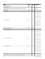
Tab.1
Overview table
Documentation
Contents
Intended for
Technical information
Planning documents
Description of function
Technical data/circuit diagrams
Basic equipment and accessories
Application examples
Call-for-tender texts
Planner, installer, customer
Installation manual
– Extended information
Intended use
Technical data/circuit diagram
Regulations, standards, CE
Notes for installation location
Application example, Standard application
Commissioning, operation and programming
Maintenance
Installer
User manual
Commissioning
Operation
User settings/programming
Fault table
Cleaning/maintenance
Energy-saving tips
Customer
Asset ledger
Commissioning report
Check list for commissioning
Maintenance
Installer
Abridged instructions
Operation in brief
Customer
Accessories
Installation
Operation
Installer, customer
2.3
Symbols used
2.3.1 Symbols used in the manual
This manual uses various danger levels to draw attention to special in
structions. We do this to improve user safety, to prevent problems and to
guarantee correct operation of the appliance.
10
7636047 - 02 - 24082015
2 About this manual
Danger
Risk of dangerous situations resulting in serious personal injury.
Danger of electric shock
Risk of electric shock.
Warning
Risk of dangerous situations resulting in minor personal injury.
Caution
Risk of material damage.
Note
Please note: important information.
See
Reference to other manuals or pages in this manual.
7636047 - 02 - 24082015
11
3 Technical specifications
3
Technical specifications
3.1
Homologations
3.1.1 Regulations and standards
Beside the general technical rules, the relevant standards, regulations, or
dinances and guidelines should be followed:
DIN 4109; Noise protection in construction engineering
DIN EN 12828; Heating systems in buildings
EnEV - Energy saving regulation
Federal Immission Control Ordinance 3. BImSchV
DVGW-TRGI 2008 (DVGW worksheet G 600); Technical rules for gas
installation
TRF; Technical rules LPG
DVGW code of practice G 613; Gas appliances - Installation, mainte
nance and operating instructions
DIN 18380; Heating plants and central hot water plants (VOB)
DIN EN 12831; Heating plants in buildings
DIN 4753-6: Domestic hot water calorifiers Domestic hot water heating
system and storage tanks for heated water
DIN 1988; Technical Rules for drinking water installations (TRWI)
VDE 0700-102, DIN EN 60335-2-102: Safety of electrical appliances for
household use and similar purposes: Special requirements for gas-, oilund solid fuel appliances with electrical connections
Fuel Ordinance, State Ordinances
Regulations of the local Electricity Board
Obligation to register (possibly. Group Exemption Regulation )
ATV-Code-of-practice M251 of the waste water technology association
Regulations of the public authorities for the run-off of condensate.
3.1.2 Manufacturer’s Declaration
Meeting the protection requirements according to guideline 2004/108/EC
for electromagnetic compatibility (EMC) is only guaranteed when the boiler
is operated according to purpose.
The ambient conditions according EN 55014 must be met.
Operation is only allowed with the casing fitted correctly.
Correct electric earthing must be ensured by regular checks (e.g. annual
inspection) of the boiler.
When appliance parts need replacing, only original parts as specified by
the manufacturer may be used.
The gas condensing-boilers fulfil the basic requirements of the Efficiency
Guideline 92/42/EC as condensing boiler.
When natural gas is used, the gas condensing boilers emit less than 60
kWh NOX corresponding to the requirements as per §6 of the Ordinance
mg/
regarding small firing places dated 26.01.2010 (1st BImSchV).
3.2
Technical data
3.2.1 Technical data – Boiler space heaters in accordance with
ErP guideline
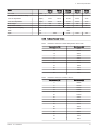
Tab.2
Technical data for boiler space heaters in accordance with ErP guideline
Product name
Condensing boiler
12
EC four
125 kW
EC four
170 kW
EC four
215 kW
EC four
260 kW
EC four
300 kW
Yes
Yes
Yes
Yes
Yes
7636047 - 02 - 24082015
3 Technical specifications
Product name
EC four
125 kW
EC four
170 kW
EC four
215 kW
EC four
260 kW
EC four
300 kW
Low-temperature boiler(1)
No
No
No
No
No
B1 boiler
No
No
No
No
No
Cogeneration space heater
No
No
No
No
No
Combination heater
No
No
No
No
No
kW
122
166
210
255
294
Useful heat output at rated heat out P4
put and high temperature mode(2)
kW
121.6
165.8
210.1
254.5
294.0
Useful heat output at 30% of rated
heat output and low temperature
mode(1)
P1
kW
40.5
55.2
69.7
84.4
97.3
Seasonal space heating energy effi
ciency
ƞs
%
–
–
–
–
–
Useful efficiency at rated heat output ƞ4
and high temperature mode(2)
%
87.7
87.8
88.0
88.2
88.3
ƞ1
%
97.4
97.5
97.4
97.5
97.4
Full load
elmax
kW
0.170
0.200
0.330
0.350
0.410
Part load
elmin
kW
0.031
0.034
0.040
0.046
0.051
Standby mode
PSB
kW
0.004
0.004
0.004
0.004
0.004
Standby heat loss
Pstby
kW
0.180
0.224
0.258
0.281
0.288
Ignition burner power consumption
Pign
kW
0.0
0.0
0.0
0.0
0.0
Annual energy consumption
QHE
GJ
–
–
–
–
–
Sound power level, indoors
LWA
dB
66
67
67
67
68
Emissions of nitrogen oxides
NOX
mg/kW
h
38
38
39
39
39
Rated heat output
Useful heat output at 30% of rated
heat output and low temperature
mode(1)
Prated
Auxiliary electricity consumption
Other items
(1) Low temperature mode means for condensing boilers 30 °C, for low temperature boilers 37 °C and for other heaters 50 °C return tem
perature (at heater inlet).
(2) High temperature mode means 60°C return temperature at heater inlet and 80°C feed temperature at heater outlet.
See
The back cover for contact details.
3.2.2 Technical data
Model
EC four
125 kW
EC four
170 kW
EC four
215 kW
EC four
260 kW
Product ID no.
CE-0085 CL 0072
VDE Reg. No.
40017550
Gas category
II2H3+
Installation types
B23, C33, C53, C63X, C83
Software version
V 4.2
EC four
300 kW
Nominal heat input range
Natural gas
Heating
kW
20.0-125.0
28.0-170.0
35.0-215.0
42.0-260.0
48.0-300.0
LPG
Heating
kW
35.0-125.0
35.0-170.0
48.0-215.0
58.0-260.0
58.0-300.0
Nominal heat output range
7636047 - 02 - 24082015
13
3 Technical specifications
Model
Natural gas
LPG
Standard utilisation (Hi/Hs)
EC four
125 kW
EC four
170 kW
EC four
215 kW
EC four
260 kW
EC four
300 kW
80/60°C
kW
19.2-121.6
26.8-165.8
33.5-210.1
40.2-254.5
45.9-294.3
50/30°C
kW
21.3-133.1
29.8-181.3
37.4-229.6
44.9-278.1
52.3-322.1
80/60°C
kW
33.5-121.6
33.5-165.8
46.0-210.1
55.5-254.5
55.9-294.3
50/30°C
kW
37.2-133.1
37.3-181.3
51.2-229.6
62.0-278.1
63.2-322.1
75/60°C
%
106.5/95.5
106.6/95.6
106.6/95.6
106.7/95.7
106.7/95.7
40/30°C
%
109.5/98.5
109.6/98.6
109.6/98.6
109.7/98.7
109.7/98.7
Data for design of the chimney to DIN EN 13384 (room air-dependant operation)
Flue gas temperature
80/60°C
°C
57-61
57-61
57-60
57-61
56-60
50/30°C
°C
30-37
30-37
30-37
30-38
30-37
80/60°C
g/s
9.1-56.8
12.7-77.2
15.9-97.6
19.1-118.1
21.8-136.2
50/30°C
g/s
8.2-52.3
11.5-71.1
14.4-89.4
17.4-108.3
19.7-124.5
80/60°C
g/s
15.1-53.9
15.1-73.2
20.7-92.6
25.0-112.0
25.0-129.2
50/30°C
g/s
14.2-49.4
13.9-67.1
19.2-84.4
23.3-102.2
22.9-117.6
NOx standard emission factor
75/60°C
mg/kWh
35
CO standard emission factor
50/30°C
mg/kWh
15
Flue gas mass flow rate
with natural gas
For liquid gas
Supply pressure for natural gas
min. 18 mbar - max. 25 mbar
CO2 content natural gas
%
9.3 (9.1-9.5 allowed)
Supply pressure LPG
min.42.5 mbar - max. 57.5 mbar
CO2 content LPG
%
11.0 (10.8-11.2 allowed)
pH value condensed water before
neutralisation
Volume condensed water
4-5
40/30°C
l/h
Max. delivery pressure at flue gas outlet
mbar
Flue gas connection
mm
3.0-16.6
4.3-22.6
5.4-29.9
6.0-36.5
7.6-42.4
1.0
160
200
Connection values
IP rating
IP 20
Electrical connection
230 V~ / 50Hz, max. 6.3 A
Max. electr. power consumption
W
170
200
330
350
410
EnEV-values
%
0.24
0.22
0.20
0.18
0.16
Standby losses qB, 70
%
0.24
0.22
0.20
0.18
0.16
Efficiency η100
%
97.3
97.5
97.7
97.9
98.1
Efficiency η100
%
108.8
108.8
108.9
109.0
109.0
Demand on auxiliary energy PHE,
100
170
200
330
350
410
Demand on auxiliary energy PHE,
100
31
34
40
46
51
Max. water pressure
6.0 bar / 0.6 MPa
Max. operating temperature (protection)
°C
110
Max. flow temp
°C
90
Volume flow
∆T = 20 K
kg/h
5375
7310
9245
11180
12900
∆T = 10 K
kg/h
10750
14620
18490
22360
25800
mbar
28
34
37
39
40
Hydraulic resistance
∆T = 20 K
14
7636047 - 02 - 24082015
3 Technical specifications
Model
EC four
125 kW
EC four
170 kW
EC four
215 kW
EC four
260 kW
EC four
300 kW
mbar
109
132
146
154
156
room air-dependent
dB(A)
40-51
40-51
40-52
40-53
40-54
room air-independent
dB(A)
39-50
39-50
39-51
40-52
40-53
Boiler weight
kg
205
240
285
314
344
Boiler water content
l
29
34
38
45
53
Height above everything
mm
1455
Width
mm
692
Depth
mm
1264
1357
∆T = 10 K
Sound pressure level 1 m away
1008
1171
3.2.3 Tables of sensor values
Tab.3
Tab.4
7636047 - 02 - 24082015
Resistance values for outside temperature sensor ATF
Temperature [°C]
Resistance [Ω]
-20
8194
-15
6256
-10
4825
-5
3758
0
2954
5
2342
10
1872
15
1508
20
1224
25
1000
30
823
Resistance values for all other sensors
Temperature [°C]
Resistance [Ω]
0
32555
5
25339
10
19873
15
15699
20
12488
25
10000
30
8059
35
6535
40
5330
45
4372
50
3605
55
2989
60
2490
65
2084
70
1753
75
1481
15
3 Technical specifications
Temperature [°C]
Resistance [Ω]
80
1256
85
1070
90
915
95
786
100
677
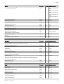
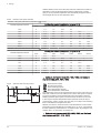
3.2.4 Pressure drop secondary circuit
Fig.1
Pressure drop secondary circuit
350
300
WW [mbar]
250
200
1
150
2
100
5
3
50
4
0
0
5
10
15
20
25
WMS [m3 /h]
WW
WM
S
1
2
3
4
5
16
30
35
40
RA-0000209
Pressure drop secondary circuit
Water mass flow
EC four 125 kW
EC four 170 kW
EC four 215 kW
EC four 260 kW
EC four 300 kW
7636047 - 02 - 24082015
3 Technical specifications
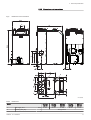
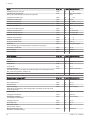
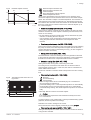
3.2.5 Dimensions and connections
Fig.2
Dimensions and connections
692
A
204
L
H
1389
B
I
K
M
C
D
E
3
280
320
302
122
2
96
5
1
F
G
4
RA-0000208
Tab.5
Dimensions
Model
1
Air supply duct
2
Heating flow (HV)
7636047 - 02 - 24082015
mm
EC four
125 kW
EC four
170 kW
EC four
215 kW
EC four
260 kW
EC four
300 kW
Ø 110
Ø 110
Ø 125
Ø 125
Ø 125
Flange DN 65
17
3 Technical specifications
Model
EC four
125 kW
EC four
170 kW
EC four
215 kW
EC four
260 kW
EC four
300 kW
3
Heating return (HR)
4
Gas connection
R 1"
R 1½"
Flange DN 65
R 1½"
R 1½"
R 1½"
5
Safety group connection
R 1"
R 1"
R 1¼"
R 1¼"
R 1¼"
Dimension A
mm
160
160
200
200
200
Dimension B
mm
1008
1008
1171
1264
1357
Dimension C
mm
301
301
351
351
351
Dimension D
mm
401
401
514
607
700
Dimension E
mm
134
134
163
163
163
Dimension F
mm
14
14
14
14
14
Dimension G
mm
687
687
851
944
1037
Dimension H
mm
530
530
530
630
630
Dimension I
mm
30
30
90
90
90
Dimension K
mm
139
139
50
50
50
Dimension L
mm
450
450
202
202
202
Dimension M
mm
150
150
167
167
167
18
7636047 - 02 - 24082015
3 Technical specifications
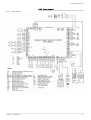
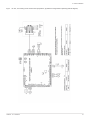
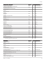
3.2.6 Wiring diagram
Fig.3
Wiring diagram
7636047 - 02 - 24082015
19
4 Description of the product
4
4.1
Description of the product
Main components
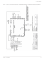
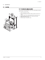
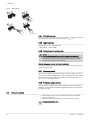
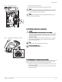
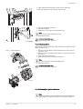
4.1.1 Boiler
Fig.4
Boiler view EC four 125 kW - 170 kW
1
2
3
4
5
6
7
8
9
10
11
12
13
14
15
16
17
1
2
3
4
5
6
7
8
9
10
11
12
13
14
15
16
17
18
19
20
Flue gas connection
Boiler flow (KV)
Safety group connection
Boiler return (KR)
Air supply duct
Gas connection
Boiler control LMS
Ignition transformer (below the control unit)
Ionization electrode
Flame inspection window (below the control unit)
Fan
Ignition electrode block
Venturi
Gas valve
Heat exchanger
Flue gas silencer
Pressure sensor
Filling and drain valve
Cleaning cover
Siphon
1
2
3
4
5
6
7
8
9
10
11
12
13
14
15
16
17
18
19
20
Flue gas connection
Boiler flow (KV)
Safety group connection
Boiler return (KR)
Air supply duct
Gas connection
Boiler control LMS
Ignition transformer (below the control unit)
Ionization electrode
Flame inspection window (below the control unit)
Fan
Ignition electrode block
Venturi
Heat exchanger
Gas valve
Flue gas silencer
Pressure sensor
Filling and drain valve
Cleaning cover
Siphon
18
19
20
RA-0000211
Fig.5
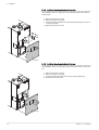
Boiler view EC four 215 kW - 300 kW
1
2
3
4
5
6
7
8
9
10
11
12
13
14
15
16
17
18
19
20
RA-0000212
20
7636047 - 02 - 24082015
4 Description of the product
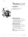
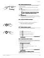
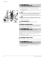
4.1.2 Room device RGT
Remote setting of all adjustable control functions of the basic appliance is
possible using the room device RGT (Figure 1, page 21).
Fig.6
Operating interface of the room de
vice RGT
1
2
3
4
5
6
7
8
1
2
3
Operating mode key, heating mode
Operating mode key domestic water mode
Screen
ESC key (cancel)
OK key (acknowledgement)
Presence key
Control knob
Information key
Presence key
Manual switching over between heating operation at comfort nominal val
ue and heating operation at reduced nominal value is possible with the
presence key, irrespective of the set time programmes. The value switch
ed over to stays active until the next modification by the time programme.
4
5
6
7
8
sRE037A
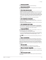
Control panel description
4.2
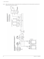
4.2.1 Operating elements
Fig.7
1
2
3
4
5
6
7
8
9
10
11
12
Operating elements
1
3
2
ON/OFF switch
Reset button burner control
Blanking plate
Reset safety temperature limiter (STB)
Operating mode key domestic water mode
Operating mode key, heating mode
Screen
OK key (acknowledgement)
Information key
Control knob
ESC key (cancel)
Chimney-sweep button
4
6
5
7
8
9
RA-0000214
12 11
10
7636047 - 02 - 24082015
21
4 Description of the product
4.2.2 Displays
Fig.8
Symbols on the display
sRE081B
4.3
Heating to comfort setpoint
Heating to reduced setpoint
Heating to frost protection setpoint
Current process
Holiday function active
Reference to heating circuits
Burner in operation (boiler only)
Cooling active (heat pump only)
Compressor in operation (heat pump only)
Maintenance message
Fault message
Information level active
Setting level active
Heating system switched off (automatic summer/winter changeover
or automatic heating limit active)
Accessories and options
4.3.1 Accessories
A list of the accessories (selection) available for the EC four can be
found below:
4.3.2 Installation of extension modules
More application options are available by installing up to 3 extension mod
ules of the series EWM B (accessories) (mixer heating circuit, solar con
nection).
See
More information about the extension module EWM can be found
in the Installation instructions extension module EWM.
22
7636047 - 02 - 24082015
5 Before installation
5
5.1
Before installation
Regulations governing installation
Caution
Installation of the appliance must be done by a qualified engineer
in accordance with prevailing local and national regulations.
5.2
Installation requirements
5.2.1 Corrosion protection
Caution
Risk of damage to the device!
The combustion air must be free from corrosive elements - espe
cially vapours containing fluorine and chlorine which are found, for
example, in solvents and cleaning agents, propellant gases etc.
When connecting heat generators to under-floor heating systems
employing plastic pipes which are not impervious to oxygen in ac
cordance to DIN 4726, heat exchangers must be used for separa
tion purposes. In the case of closed heating systems, the filling
water does not usually need to be treating for corrosion. This de
pends on the water hardness and system volume for the respec
tive boiler types. VDI directive 2035-2 specifies that a pH value of
9 must never be exceeded. The pH value can change during oper
ation of the heating system due to CO2 formation in connection
with lime sediment, and must be checked once a year during
maintenance. For heating systems and piping with is not impervi
ous to oxygen, system separation between the boiler and other
system components at risk of corrosion must be used.
5.2.2 Supply air openings
Caution
Keep the inflow area clear.
Never block or close off ventilation apertures. The inflow area for
combustion air must be kept clear.
Warning
Risk of damage.
The gas condensing boiler may only be installed in rooms with
clean combustion air. Foreign matter such as pollen must never
filter through the inlet apertures to reach the inside of the appli
ance. The boiler must not be started up if there is heavy dust de
velopment e.g. during construction work. There could be damage
to the boiler.
Where the EC four is operated based on room ventilation, there must be a
sufficiently large opening for combustion air available in the installation
room. The operator must be informed that this opening must never be
closed or blocked and that the connecting piece for combustion air on the
upper side of the EC four must be kept free at all times.
7636047 - 02 - 24082015
23
5 Before installation
5.2.3 Heating water requirements
Caution
Observe the heating water quality requirements!
Requirements regarding heating water quality have increased in
recent times as system conditions have changed:
lower heat demand
use of gas condensing boilers in cascade in larger projects
increased use of buffer storage tanks in combination with solar
thermal systems and solid fuel boilers.
The focus is always on designing systems that guarantee troublefree service over a long period.
Generally speaking, the quality of drinking water is adequate, but it must
be checked whether the drinking water actually filled into the system is
suitable when its hardness is taken into consideration (see water hardness
diagram). Where that is not the case, different steps can be taken:
1. Using an additive in the fill water to prevent the hardness (lime) sepa
rating inside the boiler and to ensure that the pH value of the system
water remains stable (hardness stabiliser).
2. Use of a softening system to treat the fill water.
3. Use of a desalination system to treat the fill water.
Desalination of fill and top-up water to obtain fully desalinated water
should not be mistaken for softening down to 0 °dH. Corrosive salts
remain in the water with softening.
Caution
Use only approved additives and processes.
When using additives, use only agents approved by Potterton.
Softening and desalination must also only be carried out with sys
tems approved by Potterton and with observation of the specified
limits.
Failure to observe this rule voids the warranty.
Caution
Check the pH value.
Certain conditions may result in automatic alkalisation (raising the
pH value) of the system water. The pH value should therefore be
checked annually.
The pH value must be between 8.2 and 9.0.
VDI Directive 2035 parts 1 and 2
Generally, the requirements concerning heating water to VDI Directive
2035 parts 1 and 2 apply to all boiler sizes.
A restricting factor to VDI 2035 is that the partial softening of the water
below 6 °dH is not permissible. Apply full desalination only in conjunc
tion with pH stabilisation.
The under-floor heating circuit has to be treated separately. In this con
text, contact a manufacturer of water additives or the pipework supplier
(see above).
Caution
Adherence to the conditions issued by Potterton is vital to safe
guard the warranty.
Note
The water hardness of the heating water has to be checked within
the scope of the recommended maintenance of the boiler and the
corresponding amount of additive has to be added if necessary.
5.2.4 Further information on the heating water
The water must not contain any foreign matter, such as sweat beads,
rust particles, scale or sludge. During commissioning, flush the system
until only clean water runs out. When flushing the system,ensure that
the water does not flow through the heat exchanger of the boiler, that
24
7636047 - 02 - 24082015
5 Before installation
the thermostatic radiator valves are removed and the valve inserts are
set to the maximum flow rate.
If additives are used it is important to follow the instructions of the manu
facturer.
If, in a special case, it is necessary to use additives in a mixture (e.g.
hardness stabiliser, frost protection agent, sealing agent etc.) care must
be taken that the agents are compatible with each other and the pH-val
ue is not altered. Preferably, agents from the same manufacturer should
be used.
For buffer storage tanks in combination with solar systems or solid fuel
boilers the buffer contents must be taken into consideration when deter
mining the fill water volume.
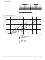
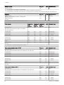
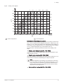
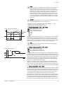
5.2.5 Diagram of water hardness
Fig.9
Diagram of water hardness
Vmax [m 3 ]
6,0
EC four 300
5,5
EC four 260
5,0
4,5
EC four 215
Water volume
4,0
EC four 170
3,5
3,0
EC four 125
2,5
2,0
1,5
1,0
0,5
RA-0000371
0,0
0
2
4
6
8
10
1,5
12
14
16
18
20
22
24
26
28
30
32
34
2,5
Water hardness
36
38
40 °E
mmol/l
Description: The boiler type, the water hardness and the water volume of
the heating system must be known. If the volume is above the curve, a
partial softening of the tap water or addition of hardness stabiliser is re
quired.
Example:
EC four 125, water hardness 14 °E, system volume 1.5 m3 → no additive
required
The usual refill volume of the heating system has been taken into account.
5.2.6 Treating and preparing the heating water
Determining the system volume
The total water volume in the heating system is calculated using the sys
tem volume (= fill water volume) plus the top-up water volume. In the
Potterton boiler-specific diagrams only the system volume is given to make
them easier to read. Over the entire service life of the boiler, a maximum
top-up volume of twice the system volume is assumed.
7636047 - 02 - 24082015
25
5 Before installation
Released media
Additives
The following products are currently released by Potterton:The following
products are currently released by Potterton:
“Full heating protection” from Fernox (www.fernox.com)
“Sentinel X100” from Guanako (www.sentinel-solutions.net)
“Jenaqua 100 and 110” from Guanako (www.jenaqua.de)
“Full protection Genosafe A” from Grünbeck
“Care Sentinel X100” from Conel (www.conel-gmbh.de)
Complete desalination
As a general rule, fully desalinated water can always be used, although
a pH value stabiliser is also required. The following products for produc
ing fully desalinated water have been tested and approved:
“Complete desalination (VE) GENODEST Vario GDE 2000" from
Grünbeck (www.gruenbeck.de)
“Complete desalination cartridge SureFill” from Sentinel (www.senti
nel-solutions.net)
more devices on request
Partial softening
The following products are currently released by Potterton:
Sodium ion exchanger “Fillsoft” from Reflex (www.reflex.de)
“Heifisoft” from Judo (www.judo-online.de)
“Heating water softening 3200” from Syr (www.syr.de)
“AQA therm” and “HBA 100” from BWT Wassertechnik (www.bwt.de)
“SoluTECH” from Cillit (www.gc-gruppe.de)
It must be ensured with an automatic blending device that the min. hard
ness is not less than 6°dH .
See
The specifications of the manufacturer must be followed.
Further makes are currently undergoing testing. Please ask Potterton for
more information.
Caution
If non-approved products are used, the guarantee becomes void.
Antifreeze agent
Note
The use of antifreeze agents with Potterton gas condensing boil
ers with aluminium heat exchangers.
The heat transfer medium (Lasacor® LS 1) offered for solar thermal sys
tems is also used in heating systems (e.g. holiday houses) as an anti
freeze agent, In the mixture supplied in the canisters (42 % Lasacor® LS
1, 58 % water), the freezing point ("crystal formation point" ) is -28°C. Due
to the lower thermal capacity and higher viscosity compared with water,
boiling noises can occur under unfavourable conditions.
For most heating systems, frost protection down to -28 °C is not required;
-15 °C is usually sufficient. The heat transfer medium must be diluted 2:1
with water to set this operating point. This mixing ratio has been tested by
Potterton in relation to its practical suitability for use with gas condensing
boilers.
Note
Up to a mixing ratio of 2.5:1 the heat transfer medium Lasacor®
LS 1 is approved as an antifreeze agent down to -15 °C for use
with Potterton gas condensing boilers.
26
7636047 - 02 - 24082015
5 Before installation
Caution
Keep the installation room frost-free.
If an antifreeze agent is used, pipework, radiators and gas con
densing boilers are protected against frost damage. For the gas
condensing boiler to be ready for operation at any time, suitable
measures must also be taken to keep the installation room frostfree. If applicable, please also note special measures for any in
stalled domestic hot water calorifiers.
The table shows the relevant amounts of heat transfer medium and water
that need to be mixed together for varying volumes of water. If other frost
protection temperatures are required in exceptional cases, individual cal
culations can be made on the basis of this table.
Amount
Water content of
the system
Lasacor® LS 1
[l]
[l]
Water in the mix
ture(1)
[l]
Frost protec
tion down to
[°C]
50
36
14
-15
100
71
29
-15
150
107
43
-15
200
143
57
-15
250
178
72
-15
300
214
86
-15
500
357
143
-15
1000
714
286
-15
(1) The water for the mixture must be neutral (potable water quality with no
more than 100 mg/kg chlorine) or demineralised. Please also follow the
manufacturer instructions.
5.2.7 Water hardness tips
1. With reference to the specific system volume (e.g. when using heating
water buffer storage tanks), determine which requirements apply re
garding total hardness of the fill and top-up water to VDI directive
2035 and the following table.
If partial softening to 6°dH is insufficient according to the project-spe
cific water hardness diagram, use either an additive or use only fully
desalinated water (with pH stabiliser).
If a boiler is replaced in an existing system, we recommend installing a
dirt trap or filter in the system return, upstream of the boiler. Flush the
system thoroughly.
2. Depending on the materials used, determine whether the addition of
inhibitors, partial softening or full desalination is the best method.
3. Record the filling process (If an additive is used, note this on the boil
er). To prevent gas pockets and bubbles, it is essential to fully vent
the system at maximum operating temperature.
4. After 8 to 12 weeks, check and record the pH value. Offer and con
clude a maintenance contract.
5. Once a year, check the system is operating correctly with regard to
pressure maintenance, pH value and the volume of top-up water
used.
Tab.6
Table to VDI 2035 Sheet 1
Total heating output
in kW
7636047 - 02 - 24082015
Total hardness in °dH
subject to the specific system volume
< 20 l/kW
≥ 20 l/kW and
< 50l/kW
≥ 50 l/kW
< 50(1)
≤ 16.8
≤ 11.2
< 0.11
50 - 200
≤ 11.2
≤ 8.4
< 0.11
200 - 600
≤ 8.4
≤ 0.11
< 0.11
27
5 Before installation
Total heating output
in kW
> 600
Total hardness in °dH
subject to the specific system volume
< 20 l/kW
≥ 20 l/kW and
< 50l/kW
≥ 50 l/kW
≤ 0.11
< 0.11
< 0.11
(1) for system boilers (< 0.3 l/kW) and systems with electric heating elements
5.3
Choice of the location
5.3.1 Notes for installation location
Caution
Danger of damage from water!
The following must be observed when installing the EC four:
In order to prevent damage due to water, particularly due to leak
ages in the DHW storage tank, suitable precautionary measures
should be taken regarding installation.
Installation room
The installation room must be dry, the room temperature must be be
tween 0°C and 45°C.
The installation location has to be selected particularly with respect to
the routing of the flue gas pipes. When installing the boiler, the specified
wall clearances have to be maintained.
Along with the general rules of the technology, especially the regulations
of the federal German states, such as fire and construction ordinances
as well as heating room guidelines, must be observed. There should be
sufficient space in front of the equipment to carry out inspection and
maintenance work.
Caution
Risk of damage to the device!
Aggressive foreign substances in the combustion supply air can
destroy or damage the heat generator. Therefore installation in
rooms with high humidity (see also "Operation in wet rooms") or
heavy dust accumulation is only allowed with
room air independent operating modes.
If the EC four is operated in rooms in which solvents, cleaning
agents containing chlorine, paints, glues or similar substances are
worked with or in which such substances are stored, only room air
independent operation is permissible. This applies especially for
rooms in which ammonia and its compounds are heavily used, as
well as nitrites and sulphides (animal breeding and recycling facili
ties, battery and galvanising rooms, etc.).
During the installation of the EC four under these conditions DIN
50929 (Corrosion probability of metallic materials with external
corrosion loading) as well as information sheet i. 158; “German
Copper Institute” is heeded.
Caution
Risk of damage to the device!
Furthermore it is to be observed that under aggressive atmos
pheres even installations outside the boiler can be corroded. This
particularly includes aluminium, brass and copper installations.
These must be replaced by plastic-coated pipes in the factory in
accordance with DIN 30672. Fittings, pipe joints and shaped
pieces must be appropriately made from shrink tube in the per
formance classes B and C.
For damages occurring due to the installation in an unsuitable location or
based on improper combustion air supply, no warranty claims may be
made.
28
7636047 - 02 - 24082015
5 Before installation
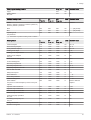
5.3.2 Space requirement
Recommended space requirement
Dimension
A
B
D
Fig.10
C
EC four
170 kW
EC four
215 kW
EC four
260 kW
EC four
300 kW
60 cm
70 cm
80 cm
90 cm
100 cm
Dimension
B
50 cm
Dimension
C
50 cm
Dimension
D
10 cm
A
C
EC four
125 kW
RA-0000216
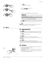
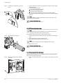
5.4
Fig.11
Transport
Transport equipment
1
Carrying fixtures
2
Eyebolt
For transporting the boiler to the installation location using a crane, the
eyebolt located on the top of the boiler can be used. Remove the central
casing cover of the EC four to do this.
2
For the transport of the boiler to installation location manually, push 2 suffi
ciently large steel pipes (Ø = 1", not included!) through the carrying fixture
so that the boiler can be lifted and transported.
Danger
Risk of injury!
The boiler must be safely secured from any sliding on the steel
pipes! Safety gloves must always be worn during manual trans
port. At least 4 people are required for transport with the aid of a
carrying fixture.
1
1
RA-0000218
7636047 - 02 - 24082015
29
5 Before installation
5.5
Connecting diagrams
5.5.1 Application examples
EC four, one heating circuit and hot water preparation, AguaSave and AguaClean optional (hydraulic diagram)
four
Fig.12
30
7636047 - 02 - 24082015
5 Before installation
EC four, one heating circuit and hot water preparation, AguaSave and AguaClean optional (hydraulic diagram)
four:
four
Fig.13
7636047 - 02 - 24082015
31
5 Before installation
EC four, one mixed heating circuit and hot water preparation, AguaSave and AguaClean optional (hydraulic diagram)
four
Fig.14
32
7636047 - 02 - 24082015
5 Before installation
EC four, one mixed heating circuit and hot water preparation, AguaSave and AguaClean optional (hydraulic diagram)
four:
Fig.15
7636047 - 02 - 24082015
33
5 Before installation
EC four, 3 mixed heating circuits and hot water preparation, AguaSave and AguaClean optional (hydraulic diagram)
four
Fig.16
34
7636047 - 02 - 24082015
5 Before installation
EC four, 3 mixed heating circuits and hot water preparation, AguaSave and AguaClean optional (hydraulic diagram)
Eurocondense four:
Fig.17
7636047 - 02 - 24082015
35
5 Before installation
Boiler cascade with 2 EC four, 3 mixing heating circuits, hydraulic Bypass and hot water preparation, AguaSave and
AguaClean optional (hydraulic diagram)
four
four
Fig.18
36
7636047 - 02 - 24082015
5 Before installation
Fig.19
Boiler cascade with 2 EC four, 3 mixing heating circuits, hydraulic Bypass and hot water preparation, AguaSave and
AguaClean optional (hydraulic diagram)
7636047 - 02 - 24082015
37
5 Before installation
Boiler cascade with 2 EC four, 3 mixing heating circuits, hydraulic Bypass and hot water preparation, AguaSave and
AguaClean optional (hydraulic diagram)
four
four
Fig.20
38
7636047 - 02 - 24082015
5 Before installation
5.5.2 Legend
Fig.21
Legend for application examples; part 1
7636047 - 02 - 24082015
39
5 Before installation
Fig.22
40
Legend for application examples; part 2
7636047 - 02 - 24082015
6 Installation
6
Installation
6.1
Mounting
6.1.1 Converting the exhaust connection
The conversion of the top passage to the side or rear passage of the flue
gas connection is shown below.
1. Remove the lower rear wall.
2. Remove the flue gas connection leading upward and insert an 87°
elbow
3. Turn 87° elbow to the desired position (side or towards the rear)
4. Remove either the rear cover plate or the side cover plate
5. Replace the lower rear wall
6. Glue the upper cover plate in place
6
4
3
2
4
1
RA-0000359
7636047 - 02 - 24082015
41
6 Installation
6.1.2 Installing the air supply duct at the side
The installation of the air supply duct on the left-hand side of the boiler is
shown below.
1. Remove the lower rear wall
2. Remove the side cover plate
3. Insert the intake pipe elbow onto the existing intake pipe and turn in
to the side position
4. Replace the lower rear wall
2
3
1
RA-0000360
6.1.3 Installing the air supply duct at the rear
The installation of the air supply duct on the rear of the boiler is shown be
low.
1.
2.
3.
4.
Remove the lower rear wall
Remove the rear cover plate
Insert the intake pipe extension onto the existing intake pipe
Mount the lower rear wall
3
2
1
RA-0000361
42
7636047 - 02 - 24082015
6 Installation
6.2
Hydraulic connection
6.2.1 Connecting the heating circuit
6.2.2 Safety valve
In the case of open heating plants, a safety supply and return pipeline
must be connected; in the case of closed heating plants a membrane ex
pansion tank and safety valve must be fitted.
Caution
The connecting pipe between boiler and safety valve must not be
blockable. The installation of pumps and fittings or pipe reducer
pieces is not permitted. The blow-off line of the safety valve must
be designed in such a way that the pressure does not increase
when the safety valve responds. It must not be routed to the out
side, the opening must be clear and observable. Any heating wa
ter that may possibly escape should be safely drained off.
6.2.3 Condensate connection
A direct run-off of the condensate into the domestic drainage system is on
ly allowed if the system only comprises corrosion resistant materials (e.g.
PP-pipe, stoneware or similar materials). If this is not the case, the
Potterton neutralisation plant must be installed (optional accessory).
The condensate must be able to flow freely into a funnel. A stench trap
must be installed between the funnel and drainage system. The conden
sate hose of the EC four must be inserted through the opening in the rear
or side wall. If there is no run-off facility underneath the condensate dis
charge, the use of the Potterton neutralisation and lifting system is recom
mended.
Note
Danger to life due to flue gas escaping!
Fill the condensate discharge with water before commissioning.
For this, fill water into the flue gas outlet before assembly of the
flue gas pipe until the siphon is completely filled. If this instruction
is not followed, flue gas may escape to the installation room.
6.3
Gas connection
6.3.1 Gas connection
The gas-side connection may only be carried out by an approved installer.
For the gas-side installation and setting, the factory setting data of the
equipment and optional label should be compared with the local supply
conditions.
An approved thermally activated disconnector valve must be installed up
stream of the gas condensing boiler.
If old gas pipes still exist in the region, the installation of a gas filter is rec
ommended.
Residues in pipes and pipe joints should be removed.
7636047 - 02 - 24082015
43
6 Installation
6.3.2 Check tightness
Danger
Danger! Danger to life by gas!
The entire gas inlet pipe, particularly the joints, must be checked
for leakages before commissioning.
The gas burner valve on the gas burner must be pressure- tested
at maximum of only 100mbar
6.3.3 Venting the gas line
The gas line must be vented before initial commissioning.
For this, open the measuring nozzle for the connecting pressure and vent,
taking the safety precautions into account. Check for tightness of the con
nection after venting.
Danger
Danger to life by gas!
The entire gas inlet pipe, particularly the joints, must be checked
for leakages before commissioning.
6.4
Air supply/flue gas connections
6.4.1 Flue gas connection
For the operation of the EC four as a gas condensing boiler, the flue gas
pipe should be designed with the flue gas temperature under 120°C (flue
gas pipe type B). The flue gas piping system SAS approved in conform
ance with building regulations is intended for this purpose.
Compilation of the necessary basic construction kits
RLA:
SAS 160-2/SAS 160-4/SAS 200
RLUA:
SAS 160-2/SAS 160-4/SAS 200 + RLUA
RLUA with wall connec
tion:
SAS 160-2/SAS 160-4/SAS 200 + RLUA +
WAS
Note
Connecting the boiler as RLUA-version (RLUA-set and possibly
WAS) may give rise to reduced output of the boiler, which is com
pensated by Potterton customer service.
Approval number
The SAS has been approved by the Deutsche Institut für Bautechnik
(DIBt) (German Institute for Civil Engineering) in general conformance with
building regulations:
Approval Number Z-7.2.-1104
44
7636047 - 02 - 24082015
6 Installation
6.4.2 Flue gas system
Fig.23
EC four with flue gas piping system SAS for room air-dependent and room air-independent operation
C33
B23
C83
B23P
C33
C53
air inlet
50 cm2 - 450 cm2
depending on boiler output
C53
air inlet
1 x 150 cm2 or
1 x 75 cm2
air inlet
1 x 150 cm2 or
1 x 75 cm2
air inlet
50 cm2 - 450 cm2
depending on boler
output
wall connection set
WAS
air inlet
1 x 150 cm2 or
1 x 75 cm2
air inlet
1 x 150 cm2 or
1 x 75 cm2
rear ventilation
rear ventilation
RA-0000415
In case of roof central heating installations, the installation of the roof
duct is only possible if the flue gas pipe can be routed directly (without
going through other rooms) through the roof.
In case of installation C33 (suction of the combustion air through vertical
roof duct) the mouth of the air pipe must be fitted with a rain hood.
In case of installation C53 and C83 (suction of the combustion air through
the outer wall) the wall connection kit WAS with filter mat and air pres
sure monitors must be used.
Flue gas pipeline lengths for room air-dependent operation
Tab.7
Permissible exhaust gas pipeline lengths for room air-dependent operation
Model
Flue gas pipe-Ø
Max. pipe length incl. 1
elbow 87°
mm
m
EC four
125 kW
EC four
170 kW
EC four
215 kW
EC four
260 kW
EC four
300 kW
160
160
160
200
160
200
160
200
60
50
30
60
18
60
8
60
These lengths only apply to single boilers.
For more elbows, the following deductions have to be made
1 elbow 87°: 5 m
1 elbow 45°: 2 m
1 elbow 15°: 1 m
A calculation by Potterton is required for individual cases of room air-inde
pendent operation of the EC four.
7636047 - 02 - 24082015
45
6 Installation
See
More information can be found in the Technical information
Flue gas pipe lengths for cascade systems
See
A table of permissible flue gas pipe lengths for cascade systems
can be found in the Technical information. A calculation by
Potterton is required for installations deriving from this.
6.4.3 General information about the exhaust gas piping system
Standards and regulations
Besides the general technical rules, the following should be partic
ularly observed:
Regulations of the accompanying certificate of approval
Implementation rules of the DVGW-TRGI, G 600
Planning laws of the German federal states in accordance with the Com
bustion Ordinance and the building regulations
Caution
Due to the different regulations in the individual federal German
states and working (flue gas evacuation, cleaning and inspection
openings etc.) varying from region to region, the district chimney
sweep officer responsible should be consulted before assembly is
started.
Contaminated chimneys
Combustion of solid and liquid fuels generates deposits and pollution in
the respective flue gas tract. Soot contaminated with sulphur and halogen
ated hydrocarbons sticks to the inside walls. Such flue gas tracts are not
suitable for the combustion air supply of heat generators without pretreat
ment. Contaminated combustion air is one of the main causes of corrosion
damage and malfunctions on fuel-burning installations. If the combustion
air has to be drawn via an existing chimney, this flue gas tract should be
inspected by the district chimney sweep officer responsible and cleaned if
necessary. Should structural deficiencies (e.g. old, broken chimney struc
tures) oppose its use as a combustion air supply duct, suitable measures
such as shake-out of the fireplace should be taken. It must be ensured
that there is no contamination of the combustion air with foreign matter.
If an appropriate clean up of the existing flue gas tract is not possible, the
heat generator can be operated on a concentric flue gas pipe independent
of ventilation. The concentric flue gas pipe must run straight in the shaft.
Lightning protection
Danger of electric shock
Danger to life due to lightning strike.
The chimney head cover must be integrated in any existing light
ning protection system and house-side potential equalisation.
This work should be carried out by an approved company special
izing in lightning protection and electrical work.
Shaft requirements
Inside buildings, exhaust gas system should be laid in suitable ventilated
shafts. The shafts must be made of non-combustible, dimensionally stable
materials.
Fire resistance duration of the shaft: 90 min.
Fire resistance duration of the shaft in case of buildings of lower building
height: 30 min.
46
7636047 - 02 - 24082015
6 Installation
6.4.4 Chimneys already in use
If a chimney used before for oil or solid fuel-fired boilers is used as a duct
for installation of a concentric exhaust gas pipeline, the chimney must be
thoroughly cleaned first by a specialist.
Note
Concentric flue gas routing, also in the duct, also in the shaft, is
absolutely necessary The concentric flue gas pipe must run
straight in the duct.
Multiple usage of air/flue gas chimneys of different manufactur
ers
The selected air/flue gas chimney must have approval by the
building supervisory authority DIBt for multiple usage opera
tion suitability.
Diameter, heights and maximum number of devices can be
taken from the design tables of the approval certificate.
Height above the roof
With regard to the minimum height above the roof, countryspecific regulations regarding chimneys and flue gas systems
are applicable.
6.4.5 Assembly of the flue gas system
Warning
Danger of injury by not wearing working gloves.
Working gloves must be worn during assembly of the flue gas sys
tem.
Mounting with gradient
The flue pipe must be routed at a gradient to the EC four so that the con
densation from the flue pipe can drain from the flue pipe to the central con
densation collector of the EC four.
The min. downward slopes are:
horizontal flue pipe: min. 3° (min. 5.5 cm per metre)
external wall duct: min. 1° (min. 2.0 cm per metre)
Shortening of the pipes
All simple and concentric pipes may be shortened. After cutting, the ends
of the pipes have to be thoroughly de-burred. When a concentric pipe is
shortened, a piece of pipe at least 6 cm long must be cut off the outer
pipe. The spring washer for centring the inner pipe becomes obsolete.
Minimum dimensions of the duct
Fig.24
Minimum dimensions of the duct
Outer Ø cou
pling
Min. duct inner dimension
System
D
[mm]
short side A
[mm]
round B
[mm]
SAS 160 (DN 160)
184
225
245
SAS 200 (DN 200)
227
256
276
Back ventilation
RA-0000159
7636047 - 02 - 24082015
For room air-depending operation of the gas condensing boiler with the
SAS 160 and SAS 200 the duct below the flue gas connection in the in
stallation room must be provided with back ventilation. The clear crosssection must be at least Amin = 125 cm2. A respective air intake grid is
available as accessory.
47
6 Installation
Assembly
Fig.25
1. The pipes and formed pieces have to be fitted together up to the con
nector basis. Only the original profile seals of the building kit or the
original spare seals may be used between the individual elements.
Before assembly, the seals must be treated with the silicone paste
which is part of the scope of delivery. When routing the pipes care
must be taken that the pipes are installed in line and without tension.
In this way leaking of the seals is prevented.
2. For fastening the support rail in the opposite wall of the duct opening,
a bore hole (d=10 mm) must be provided on the level of the opening
edge. Then the pin of the support rail has to be hammered into the
bore hole.
Assembly of the support rail
2
RA-0000157
Fig.26
Insertion into the duct
3. The flue pipe is lowered from the top into the duct. For this, connect a
rope to the support leg and insert the pipes, section by section, from
the top. To prevent the components sliding apart during assembly, the
rope must be kept on tension until the final assembly of the flue pipe.
If spacers are necessary, these have to be fitted to the duct at least
every 2 m.
Cant the spacers at a right angle and align centric in the duct. Pipes
and formed parts are to be installed in such a way that the connectors
are arranged counter to the flow direction of the condensed water.
After the pipes have been inserted, place the support leg in the sup
port rail and align (flush and without tension). The duct cover at the
chimney head must be assembled in such a way that no rainfall can
get into the space between flue pipe and duct and the air for back
ventilation can flow freely.
3
Caution
When replacing seals use new seals!
When the flue pipes are dis-assembled, new seals must be used
for the reassembly!
RA-0000158
6.4.6 Cleaning and inspection openings
Danger
Clean exhaust gas pipelines!
It should be possible to clean the flue gas pipes and inspect their
free cross-section and leakproofness.
At least one cleaning and inspection opening must be installed in the in
stallation room of the EC four.
Exhaust gas pipes in buildings, which cannot be cleaned or inspected from
their port side must have an additional cleaning port in the upper part of
the exhaust system or above the roof.
The exhaust gas pipelines at the outer wall must have at least one clean
ing opening in the lower part of the exhaust gas facility. For exhaust gas
facilities with building heights of < 15.00 m in the vertical section, a pipe
line length of < 2,00 m in the horizontal section and a maximum pipeline
diameter of 150 mm with a maximum deflection (except for deflection di
rectly at the boiler and in the shaft) one cleaning and inspection opening in
the installation room of the EC four is sufficient.
48
7636047 - 02 - 24082015
6 Installation
The ducts for exhaust gas facilities must not have any openings other than
the necessary cleaning and inspection ports as well as openings for back
ventilation of the exhaust gas pipe.
6.5
Electrical connections
6.5.1 Electrical connection (general)
Danger
Danger to life through incorrect work!
All electrical work in connection with the installation may only be
carried out by a trained electrician.
AC 230 V +6% -10%, 50 Hz
In Germany the VDE 0100 and local regulations must be followed during
installation; in all other countries, follow the relevant regulations.
The electrical connection should be made with a correct and non-reversi
ble polarity. In Germany the connection can be executed as an accessible
plug and socket connection with non-reversible polarity or as a fixed con
nection. In all other countries, a fixed connection must be provided.
For the power supply, use the power cable attached to the boiler or cable
types H05VV-F 3 x 1 mm2 or 3 x 1.5 mm2.
We recommend the installation of a mains isolator upstream of the EC
four. This should isolate all poles and provide contact separation of at
least 3 mm.
All connected components must comply with VDE [or local regulations]. Al
ways apply strain relief to connecting cables.
Cable types
Danger
Danger to life. Risk of injury or a risk to life from electric shock!
The use of rigid lines (e.g. NYM) is not allowed because of the risk
of cable damages! Flexible cables e.g H05VV-F must be used for
mains voltage and e.g. LIYY for sensor/bus cables.
6.5.2 Cable lengths
Bus/sensor lines do not have mains voltage, but safety extra-low voltage.
Never route them in parallel to mains cables (interference). Otherwise
shielded cables must be installed.
Permissible cable lengths for all sensors:
Cu-cable up to 20m: 0.8 mm2
Cu-cable up to 80m: 1 mm2
Cu-cable up to 120m: 1.5 mm2
Cable types : e.g. LIYY or LiYCY 2 x 0.8
6.5.3 Strain reliefs
All the cables should be fixed in the strain relief clamp of the control panel
and connected according to the connection diagram.
7636047 - 02 - 24082015
49
6 Installation
Fig.27
1
3
Strain reliefs
2
4
RA-0000064
6.5.4 Circulating pumps
The permissible current load per pump output is IN max = 1A.
6.5.5 Appliance fuses
Appliance fuse in the control unit ISR:
Mains fuses: T 6.3A H 250V
6.5.6 Connect sensor / components
Danger
Risk of electric shock! Danger to life through incorrect work!
The wiring diagram must be followed! Optional accessories must
be fitted and connected according to the instructions provided.
Connect to the mains. Check earthing.
Outdoor temperature sensor (included in delivery)
The outdoor temperature sensor is located in the accessory bag. For con
nection see wiring plan.
6.5.7 Replacing cables
All connecting cables, except for the mains connection cable, have to be
replaced by Potterton special cables in case of replacement. When replac
ing the mains connection cable, only cables of the types H05VV-F 3 x 1
mm2 or 3 x 1.5 mm2 may be used.
6.5.8 Protection against contact
After the EC four has been opened, the cladding parts to be screwed on
should be screwed back on with the appropriate screws to ensure protec
tion against contact.
6.6
Filling the system
1. Fill the heating system using the boiler fill and drain valve (BFD
valve) of the EC four
2. Check the system for leaks (max. water test pressure: 6 bar)
For more information, see
Boiler, page 20
50
7636047 - 02 - 24082015
7 Commissioning
7
Commissioning
7.1
General
Danger
Commissioning may only be carried out by an approved installer.
The installer checks the tightness of pipes, the correct function of
all regulating, control and safety equipment, and measures the
combustion values. If this work is not carried out correctly, there is
a risk of considerable damage to persons, environment and prop
erty.
7.2
Tab.8
Checklist for commissioning
Checklist for commissioning
1.
System location
2.
Customer
3.
Boiler type/Designa
tion
4.
Serial number
5.
6.
Characteristic gas val
ues
7.
Have all pipelines and connections been checked for tightness?
□
8.
Exhaust gas system checked?
□
9.
Gas pipeline checked and vented?
Wobbe index
kWh/m³
..........................
Operating heating value
kWh/m³
..........................
10. Static pressure measured at the gas valve inlet?
□
mbar
...............................
11. Free wheeling of pumps checked?
□
12. Filling the heating plant
□
13. Used water additives
...............................
14. Gas flow pressure measured at full load at the gas valve inlet?
mbar
...............................
15. Gas injector pressure measured at full load at the gas valve outlet?
mbar
...............................
%
...............................
17. CO-content at low load
ppm
...............................
18. CO2-content at full load
%
...............................
ppm
...............................
16. CO2-content at low load
19. CO-content at full load
20.
21.
Function test:
Heating mode
□
Domestic water mode
□
22.
Time /date
23.
Comfort setpoint heating circuit 1/2
°C
...............................
□
24. Programming:
Setpoint DHW
°C
...............................
25.
Automatic day time programme
Clock
...............................
26.
Heating curve checked?
□
27. Tightness of the flue system checked in operation (e.g. CO2 test in annular gap)?
28. Customer instructed?
□
29. Documents handed over?
□
7636047 - 02 - 24082015
51
7 Commissioning
Only components tested and marked according to the respective standard have been used.
All system components have been installed according to the instruction of the manufacturers.
The whole system conforms to the standard.
To ensure the heat source operates reliably and economically for a long period, we recom
mend annual maintenance for the heat generator.
7.3
Date /signature
Company stamp
.................................
.....
Commissioning procedure
7.3.1 Commissioning menu
The commissioning menu will be shown once during initial commissioning.
1. Change Language must be selected and confirmed with the OK but
ton.
2. Year select year and confirm.
3. Set time and date set and confirm.
4. Conclude by pressing the OK button.
RA-0000065
7.4
Note
If the commissioning menu entry is terminated by pressing ESC,
the menu will be shown again next time the appliance is switched
on.
Gas settings
7.4.1 Factory settings
The EC four has been set at nominal input by the manufacturer.
7.4.2 CO2 content
The CO2content in the exhaust gas must be checked during commission
ing and during regular maintenance of the boiler, as well as after recon
struction work on the boiler or on the exhaust gas system.
CO2 content during operation see section Technical data.
Caution
Risk of damage of the burner!
Too high CO2 values can lead to unhygienic combustion (high
CO-values) and damage to the burner.
Too low CO2 values can lead to ignition problems.
Caution
No manual setting of the gas valve possible.
The EC four automatically sets the CO2 content during operation
with the specified gas types. No manual setting of the gas valve is
possible.
7.4.3 Changing over from natural gas to LPG and vice versa
Danger
Danger to life by gas!
The gas type of the EC four may only be changed by an approved
heating specialist.
To change over to another type of gas, the CO2 content must be reset by
turning the adjustment screws on the gas valve. In addition, the parame
ters listed in the following table must be set according to the given values
in the regulator LMS.
52
7636047 - 02 - 24082015
7 Commissioning
Function
Prog. no.
Setting level
2331
Required output prepurging
EC four
125 kW
EC four
170 kW
EC four
215 kW
Natural
gas
Propane
Natural
gas
Propane
Natural
gas
Propane
F
20
35
28
35
35
48
9504
F
73
73
94
94
96
96
Required output ignition
9512
F
59.3
66.3
75.5
86.8
77.1
89.3
Required output LF
9524
F
20.0
35.0
28.0
35.0
35.0
48.0
Fan output/speed slope
9626
F
37.1
33.9
27.6
24.1
26.4
23.0
Fan output/speed Y-section
9627
F
501.1
453.9
517.2
507.4
464.4
446.3
9.3
11.0
9.3
11.0
9.3
11.0
Boiler
Output basic stage
Burner control
CO2 content (± 0.2)
Function
Prog. no.
EC four
260 kW
Setting level
EC four
300 kW
Natural gas
Propane
Natural gas
Propane
Boiler
Output basic stage
2331
F
42
58
48
58
Required output prepurging
9504
F
120
120
129
129
Required output ignition
9512
F
93.4
110.0
103.9
115.5
Required output LF
9524
F
42.0
58.0
48.0
58.0
Fan output/speed slope
9626
F
20.1
19.9
19.9
19.0
Fan output/speed Y-section
9627
F
488.0
305.7
431.7
306.1
9.3
11.0
9.3
11.0
Burner control
CO2 content (± 0.2)
Caution
Risk for the environment and the device if CO content is too high!
When a boiler set for natural gas is put into operation with LPG,
the adjustment screw for full load on the gas valve must be turned
clockwise (-) by half a turn before the boiler is switched on!
7.4.4 Manual adjustment of burner output (controller stop func
tion)
For controlling the CO2values theEC four operated in the control stop func
tion
1. Press buttonOperating mode button heating operation for approx 3 s
xxxxxxxxxxxxxx
The message Controller stop active is displayed.
2. Wait until the display has reached the basic display again.
3. Press the Info button
The message Controller stop setpoint appears on the display. The
actual modulation degree will be displayed on the display.
4. Press OK.
The setpoint can now be changed.
5. Press OK.
The setpoint displayed is then adopted by the controller.
7636047 - 02 - 24082015
53
7 Commissioning
Note
The regulator stop function is stopped by pressing the operating
mode button Heating Operation for approximately 3 seconds,
reaching the maximum boiler temperature or a time limit.
If there is demand for heat from a coiled tubing storage tank, this
demand will continue to be met during the controller stop function.
7.4.5 Adjusting CO2 content
Fig.28
Overview of gas valve
1
2
3
4
5
Compensation line
Adjustment screw for small load (Torx TX 40)
Adjustment screw for full load (Allen key 3 mm)
Gas pressure monitor
Measuring nozzle for inlet pressure
1
2
3
4
5
RA-0000225
Setting CO2 content at max. output
The CO2 content at max. output is set at the gas valve as follows:
1. EC four In the control stop function (refer to the section Control stop
function) operated at maximum value
2. Remove safety cap from the adjustment screw for full load
3. Use a 3 mm Allen key to set CO2 content at the adjustment screw
for full load according to the Technical data
Clockwise: CO2 content is decreased
Counter-clockwise: CO2 content is increased
4. Replace safety cap on the adjusting screw for full load
Setting CO2 content at min. output
The CO2 content at min. output is set at the gas valve as follows:
1. EC four In the control stop function (refer to the section Control stop
function) operated at minimum value
2. Remove safety cap from the adjustment screw for small load
3. Use a TX 40 Torx key to set CO2 content at the adjustment screw
for full load according to the Technical data
Clockwise: CO2 content is increased
Counter-clockwise: CO2 content is decreased
4. Replace safety cap on the adjusting screw for small load
Note
After successful adjustment of the gas valve, the CO2 content
must be controlled again at maximum and minimum output and
corrected if necessary
54
7636047 - 02 - 24082015
7 Commissioning
For more information, see
Technical data, page 13
GUID-6D53C28A-DD96-4E9B-915F-A733465011E0, page 0
7.5
Final instructions
7.5.1 Instruction of the customer
The customer must be given full explanation of the heating system and
how the protective installations work. He must be especially instructed
about the following:
The supply air opening must not be closed or restricted
The connection nozzle for the combustion air at the top of the device
must be accessible for the chimney sweep
The following control checks himself that he has to perform himself:
Pressure check on the manometer
Check of the receiver under the blowpipe of the safety valve
Only an approved heating specialist may carry out the inspection and
cleaning work at intervals.
7.5.2 Documents
The documents belonging to the heating plant must be handed over to
the customer with the instruction that they have to be kept in the boiler
installation room.
System log with checklist for commissioning with confirmation and legal
ly binding signature handed to the customer: Only components tested
and marked according to the respective standard have been used. All
components have been installed according to the manufacturer's in
struction. The whole system conforms to the standard.
7636047 - 02 - 24082015
55
8 Operation
8
8.1
Operation
Use of the control panel
8.1.1 Changing parameters
Settings which are not directly changed via the operating panel must be
carried out on the setting level.
The basic programming process is depicted in the following using the ex
ample of the setting of Set time and date.
1. Press OK.
The End user display is shown.
Note
If parameters are to be changed on a level other than the end user
level, please see the note below.
2. Use the control knob to select the menu item Set time and date.
3. Press OK.
Time and date
Operator section
4. Use the control knob to select the menu item Hours / minutes.
5. Press OK.
Time and date
Hours / minutes
6. Carry out hour setting (e.g. 15 h) using the control knob.
7. Press OK.
Time and date
Hours / minutes
8. Carry out minute setting (e.g. 30 minutes) with the control knob.
9. Press OK.
Time and date
Hours / minutes
10. Leave the programming level by pressing the operating mode key
for heating mode.
xxxxxxxxxxxxxx
Note
The previous menu item is retrieved by pressing the ESC key
without applying previously modified values. If no settings are car
ried out for approximately 8 minutes, the basic display is called up
without applying previously modified values.
8.1.2 Programming procedure
The selection of the setting levels and menu items is done as follows:
56
7636047 - 02 - 24082015
8 Operation
1. Press OK.
The End user display is shown.
2. Press the Info button for approx. 3 s.
The setting levels appear.
3. Select the required setting level using the control knob.
Setting levels
- End user (Eu)
- Commissioning (C), incl. end user (Eu)
- Engineer (E), incl. end user (Eu) and commissioning (C)
- OEM, includes all other setting levels (password-protected)
4. Press OK.
5. Select the required menu item (see parameter list) using the control
knob.
See
Not all menu items will be visible, depending on the selection of
the programming level and the programming.
8.2
Start-up
8.2.1 Checking water pressure
Caution
Before switching on, check whether the pressure gauge indicates
sufficient water pressure. The value should be between 1.0 and
2.5 bar.
Less than 0.5 bar: Top up water.
Caution
Observe the maximum permissible system pressure.
Over 2.5 bar: Do not put the gas condensing boiler into operation. Drain
the water.
Caution
Observe the maximum permissible system pressure.
Check that there is a drip pan below the discharge pipe from the safety
valve. In the case of overpressure, it collects heating water as it is expel
led.
8.2.2 Switching on
This section describes which steps are necessary to switch the boiler on.
1. Switch on heating emergency switch
2. Open gas shut-off device
3. Open the disconnector valves at the heating flow and heating return
on the boiler.
4. Open the operating panel cover and switch the ON/OFF switch on
the operating panel of the boiler to on.
1
RA-0000162
7636047 - 02 - 24082015
57
8 Operation
5. Use the operating mode key for heating mode to select the automat
ic operating mode on the boiler control unit
5
xxxxxxxxxxxxxx
RA-0000163
6. Set the required room temperature using the control of the control
unit
6
RA-0000164
8.2.3 Setting necessary parameters
Normally, the parameters of the regulator do not need to be modified. Only
date/time and individual time programs may need setting.
For DHW processing a setting of 55°C is recommended.
Note
Times for domestic water heating are set in time program 4 /
DHW. For reasons of convenience, domestic water heating should
start approx. 1 h before central heating commences.
8.2.4 Setting the heating mode
The operating mode key for heating mode enables a changeover between
the various heating operating modes. The selected setting is marked with
a bar underneath the operating mode symbol.
xxxxxxxxxxxxxx
Automatic mode
Heating mode according to time program
Temperature setpoints
or according to time program
Protection functions (plant frost protection, overheating protection) acti
vated
Automatic summer/winter changeover (automatic switching over be
tween heating and summer operation from a certain outside temperature
onwards)
Automatic day heating limit (automatic changeover between heating and
summer operation, if outside temperature exceeds the room setpoint
value)
Continuous mode
or
Heating mode without time program
Protection functions activated
Automatic summer/winter changeover is not activated
Automatic day heating limit is not activated
Protection mode
No heating operation
Temperature according to frost protection setpoint
Protection functions activated
Automatic summer/winter changeover active
Automatic day heating limit active
58
7636047 - 02 - 24082015
8 Operation
8.2.5 Adjusting domestic water mode
Switched on Domestic water is prepared according to the selected
switching programme.
Switched off Domestic water preparation has been de-activated.
Note
A setting between 50 and 60°C is recommended for domestic
water heating.
Times for domestic water heating are set in time program 4 /
DHW.
For reasons of convenience, domestic water heating should
start approx. 1 h before central heating commences.
XXXXXXXXXXXXXX
XXXX
Note
Legionella function
Once a week every Sunday, the legionella function is activated;
this means the domestic water is heated up to 65 °C once in order
to eliminate any legionella bacteria in the water.
8.2.6 Adjusting comfortable room setpoint
How to adjust the comfortable room setpoint is described here.
1. Set the comfort setpoint using the control knob.
=> The value is taken over automatically.
8.2.7 Setting reduced room setpoint
How to set the reduced room setpoint is described here.
1.
2.
3.
4.
5.
6.
7.
8.
Press OK.
Select the Central heating menu item.
Press OK.
Select the Reduced temp setpoint parameter.
Press OK.
Set the reduced setpoint at the control knob.
Press OK.
Leave the programming level by pressing the operating mode key
for heating mode.
8.2.8 Emergency mode (Manual control)
If the manual control function is activated the boiler is controlled to the set
point manual control. All the pumps are switched on. Additional requests
e.g. for heating domestic water are ignored.
Activating emergency operation
1.
2.
3.
4.
5.
6.
7.
8.
Press OK.
Request the menu item Maintenance.
Press OK.
Request the parameter Manual control (prog. no. 7140).
Press OK.
Select the parameter On.
Press OK.
Leave the programming level by pressing the operating mode key
for heating mode.
Adjusting setpoint for emergency operation
Using the operation mode "manual operation" you can choose a nominal
temperature value for it:
7636047 - 02 - 24082015
59
8 Operation
1.
2.
3.
4.
Press the information key.
Press OK.
Adjust nominal value by using rotating knob
Acknowledge setting with OK.
8.2.9 Chimney sweep function
The chimney sweep function is activated or deactivated using the Schorn
steinfeger-Taste.
1. Press the Schornsteinfeger-Taste .
The activated special function is displayed by the symbol
display.
in the
Note
If there is demand for heat from a coiled tubing storage tank, this
demand will continue to be met while the emissions test function
(chimney sweep function) is running.
8.2.10 Restoring factory settings
The factory settings are restored as follows:
1.
2.
3.
4.
5.
60
Press OK button
Select setting level Engineer
Select parameter Activate basic settings (prog. no. 31)
Change setting to"Yes" and wait until setting returns to "No"
Press ESC button
The factory settings have been restored.
7636047 - 02 - 24082015
9 Settings
9
Settings
9.1
List of parameters
See
Subject to system configuration, not all parameters listed in the
parameter list will be shown on the display.
To reach the end user (Eu), Commissioning (C) and Engineer
(E) setting levels:
Press the OK-Taste.
Then press the Informationstaste for approx. 3 s.
Select the circuit using the control knob.
Confirm with the OK-Taste.
Set time and date
Prog. no.
Level
Standard value
Hours / minutes
1
Eu
01:00 (h:min)
Day / month
2
Eu
01.01 (day.month)
Year
3
Eu
2030 (year)
Start of summertime
5
E
25.03 (day.month)
End of summertime
6
E
25.10 (day.month)
Operator section
Prog. no.
Level
Standard value
Change Language
20
Eu
German
Information
Temporarily | Permanently
22
E
Temporarily
Display of errors
Code | Code and text
23
E
Code and text
Contrast of display
25
Eu
—
Operation lock
Off | On
26
E
Off
Programming lock
Off | On
27
E
Off
Units
°C, bar | °F, PSI
29
Eu
°C, bar
Save basic settings(1)
No | Yes
30
E
No
Activate basic settings(2)
No | Yes
31
E
No
Used as
Room unit 1 | Room unit 2 | Room unit 3/P | Operator unit 1 | Operator unit 2 |
Operator unit 3 | Service unit
40
C
Room unit 1
Assignment device 1(3)
Temps / mode CH1 |Central heating 1 and 2 |Central Heating 1 and 3/P |All
central heatings
42
C
Temps / mode CH1
Operation CH2
Commonly with HC1 | Independently
44
C
Commonly with HC1
Operation CH3/P
Commonly with HC1 | Independently
46
C
Commonly with HC1
Room temp device 1
CH circuit 1 only | For all assigned HCs
47
C
For all assigned HCs
Occupancy button device 1
None | Temps / mode CH1 | For all assigned HCs
48
C
For all assigned HCs
Readjustment room sensor
54
E
0.0 °C
7636047 - 02 - 24082015
61
9 Settings
Operator section
Prog. no.
Level
Standard value
Software version
70
E
—
(1) This parameter is only visible in the room device.
(2) This parameter is only visible if a suitable standard setting is available in the operating unit.
(3) This parameter is only visible in the room device, as the operating unit in the boiler is programmed permanently to the operating unit.
Wireless(1)
Prog. no.
Level
Standard value
Outside sensor
Missing | In operation| No recept'n | Change batt
133
C
Missing
Delete all devices
No | Yes
140
C
No
(1) Parameters only visible if wireless room device exists.
Time program
Heating cir
cuit 1
Prog. no.
Heating cir Heating cir
cuit 3
cuit 2(1)
Prog. no.
Prog. no.
Level
Standard value
Select Mon-Sun
Mon-Sun | Mon-Fri | Sat-Sun | Mon | Tue | Wed |
Thu | Fri | Sat | Sun
500
520
540
Eu
Mon
1st Time ON
501
521
541
Eu
06:00 (h/min)
1st Time OFF
502
522
542
Eu
22:00 (h/min)
2nd Time ON
503
523
543
Eu
--:-- (h/min)
2nd Time OFF
504
524
544
Eu
--:-- (h/min)
3rd Time ON
505
525
545
Eu
--:-- (h/min)
3rd Time OFF
506
526
546
Eu
--:-- (h/min)
Copy?
515
535
555
Eu
Default values
No | Yes
516
536
556
Eu
No
Time program heating circuit 4 / DHW
Prog. no.
Level
Standard value
Select Mon-Sun
Mon-Sun | Mon-Fri | Sat-Sun | Mon | Tue | Wed | Thu | Fri | Sat | Sun
560
Eu
Mon
1st Time ON
561
Eu
05:00 (h/min)
1st Time OFF
562
Eu
22:00 (h/min)
2nd Time ON
563
Eu
--:-- (h/min)
2nd Time OFF
564
Eu
--:-- (h/min)
3rd Time ON
565
Eu
--:-- (h/min)
3rd Time OFF
566
Eu
--:-- (h/min)
Copy?
575
Eu
Default values
No | Yes
576
Eu
No
Time program heating circuit 5
Prog. no.
Level
Standard value
Select Mon-Sun
Mon-Sun | Mon-Fri | Sat-Sun | Mon | Tue | Wed | Thu | Fri | Sat | Sun
600
Eu
Mon
1st Time ON
601
Eu
06:00 (h/min)
1st Time OFF
602
Eu
22:00 (h/min)
2nd Time ON
603
Eu
--:-- (h/min)
2nd Time OFF
604
Eu
--:-- (h/min)
3rd Time ON
605
Eu
--:-- (h/min)
3rd Time OFF
606
Eu
--:-- (h/min)
(1) Parameters only visible if heating circuit is installed.
62
7636047 - 02 - 24082015
9 Settings
Time program heating circuit 5
Prog. no.
Level
Standard value
Copy?
615
Eu
Default values
No | Yes
616
Eu
No
Holidays heating circuit
1
Prog. no.
2(1)
Prog. no.
3(1)
Prog. no.
Level
Standard value
Select
Period 1 | Period 2 | Period 3 | Period 4 | Period 5 |
Period 6 | Period 7 | Period 8
641
651
661
Eu
Period 1
Start
642
652
662
Eu
—.— (day.month)
End
643
653
663
Eu
—.— (day.month)
Operating level
Off | Reduced
648
658
668
Eu
Off
Heating circuit
1
Prog. no.
2(1)
Prog. no.
3(1)
Prog. no.
Level
Standard value
Comfort setpoint
710
1010
1310
Eu
20.0 °C
Reduced temp setpoint
712
1012
1312
Eu
18 °C
Frost protection setpoint
714
1014
1314
Eu
10.0 °C
Heating curve slope
720
1020
1320
Eu
1,24
Heating curve displacement
721
1021
1321
E
0.0 °C
Heating curve adaption
Off | On
726
1026
1326
E
Off
Summer/winter heating limit
730
1030
1330
Eu
18°C
24-hour heating limit
732
1032
1332
E
0 °C
Flow temp setpoint min
740
1040
1340
E
8 °C
Flow temp setpoint max
741
1041
1341
E
80 °C
Flow temp setpoint room stat
742
1042
1342
E
- - - °C
Swi-on ratio room stat
744
1044
1344
E
---
Delay heat request
746
1046
1346
E
0s
Room influence
750
1050
1350
C
---%
Room temp limitation
760
1060
1360
E
0.5 °C
Central heating boost
770
1070
1370
E
- - - °C
Quick setback
Off | Down to reduced setpoint | Down to frost prot
setpoint
780
1080
1380
E
Down to reduced
setpoint
Optimum start control max
790
1090
1390
E
0 min
Optimum stop control max
791
1091
1391
E
0 min
Reduced setp increase start
800
1100
1400
E
- - - °C
Reduced setp increase end
801
1101
1401
E
-15 °C
Continuous pump operation
No | Yes
809
1109
1409
E
No
Overtemp protect pump circ
Off | On
820
1120
1420
E
Off
Mixing valve boost
830
1130
1430
E
5 °C
Actuator running time
834
1134
1434
E
120 s
(1) Parameters only visible if heating circuit is installed.
7636047 - 02 - 24082015
63
9 Settings
Heating circuit
1
Prog. no.
2(1)
Prog. no.
3(1)
Prog. no.
Level
Standard value
Floor curing function
Off | Functional heating | Curing heating | Curing/
functional heating | Functional/curing heating |
Manually
850
1150
1450
E
Off
Floor curing setp manually
851
1151
1451
E
25 °C
Floor curing setp current
855
1155
1455
E
- - - °C
Floor curing day current
856
1156
1456
E
0
Excess heat draw
Off | Heating mode | Always
861
1161
1461
E
Heating mode
With buffer
No | Yes
870
1170
1470
E
Yes
With prim contr/system pump
No | Yes
872
1172
1472
E
Yes
Pump speed reduction
Operating level | Characteristic
880
1180
1480
E
Characteristic
Pump speed min
882
1182
1482
C
10 %
Pump speed max
883
1183
1483
C
100 %
Curve readj at 50% speed
888
1188
1488
E
10 %
Flow setp readj speed ctrl
No | Yes
890
1190
1490
E
Yes
Operating level changeover
Off | Reduced | On
898
1198
1498
E
Reduced
Optg mode changeover
None | Off | Reduced | On | Timed
900
1200
1500
E
Off
DHW
Prog. no.
Level
Standard value
Hot water temp setpoint
1610
Eu
55 °C
Reduced temp setpoint
1612
E
45 °C
Hot water temp setpoint max
1614
E
65 °C
Release
24h/day | Time setting central heating | Time hot water
1620
Eu
Time hot water
Charging priority
Absolute | Shifting | None | MC shifting, PC absolute
1630
E
MC shifting, PC
absolute
Legionella function
Off | Periodically | Fixed weekday
1640
E
Fixed weekday
Legionella funct periodically
1641
E
3
Legionella funct weekday
Monday | Tuesday | Wednesday | Thursday | Friday | Saturday | Sunday
1642
E
Sunday
Legionella funct time
1644
E
---
Legionella funct setpoint
1645
E
65 °C
Legionella funct duration
1646
E
- - - min
Legionella funct circ pump
Off | On
1647
E
On
Circulating pump release
Time setting 3/CHP | Hot water release | Time hot water | Time auxiliary
1660
C
Hot water release
Circulating pump cycling
Off | On
1661
C
On
Circulation setpoint
1663
E
55 °C
(1) Parameters only visible if heating circuit is installed.
64
7636047 - 02 - 24082015
9 Settings
DHW
Prog. no.
Level
Standard value
Optg mode changeover
None | Off | On
1680
E
Off
Consumer circuit / swimming pool circuit
Consumer
circuit 1
Prog. no.
Consumer
circuit 2
Prog. no.
Swimming
pool circuit
Prog. no.
Level
Standard value
Flow temp setp cons request
1859
1909
1959
C
70 °C
Hot water charging priority
No | Yes
1874
1924
1974
E
Yes
Excess heat draw
Off | On
1875
1925
1975
E
On
With buffer
No | Yes
1878
1928
1978
E
Yes
With prim contr/system pump
No | Yes
1880
1930
1980
E
Yes
Swimming pool
Prog. no.
Level
Standard value
Setpoint solar heating
2055
Eu
26 °C
Setpoint source heating
2056
Eu
22 °C
Charging priority solar
Priority 1 | Priority 2 | Priority 3
2065
E
Priority 3
Swimming pool temp max
2070
E
32 °C
With solar integration
No | Yes
2080
E
Yes
Primary control/feed pump
Prog. no.
Level
Standard value
Flow temp setpoint min
2110
E
8 °C
Flow temp setpoint max
2111
E
80 °C
Syst pump on heat gen lock
Off | On
2121
E
Off
Mixing valve boost
2130
E
0 °C
Actuator running time
2134
E
120 s
Boiler
Prog. no.
Level
Standard value
Release below outside temp
2203
E
- - - °C
Full charging buffer
Off | On
2208
E
Off
Setpoint min
2210
E
20 °C
Setpoint max
2212
E
90 °C
Setpoint manual control
2214
Eu
60 °C
Burner running time min
2241
E
1 min
Burner off time min
2243
E
3 min
SD burner off time
2245
E
20 °C
Pump overrun time
2250
E
2 min
Pump overr time after HW
2253
E
5 min
Syst frost prot boiler pump
Off | On
2300
E
Off
Boiler pump on heat gen lock
Off | On
2301
E
Off
Impact heat generation lock
Heating mode only | Heating and HW mode
2305
E
Heating and HW
mode
7636047 - 02 - 24082015
65
9 Settings
Boiler
Prog. no.
Level
Standard value
Temp differential max
2316
C
---
Temp differential nominal
2317
C
15 °C
Pump modulation
None | Demand | Boiler setpoint | Temp differential nominal | Burner output
2320
E
Temp differential
nominal
Pump speed min
2322
E
10 %
Pump speed max
2323
E
100%
Output nominal
2330
E
EC four 125 kW: 125
kW
EC four 170 kW: 170
kW
EC four 215 kW: 215
kW
EC four 260 kW: 260
kW
EC four 300 kW: 300
kW
Output basic stage
2331
E
EC four 125 kW: 20
kW
EC four 170 kW: 28
kW
EC four 215 kW: 35
kW
EC four 260 kW: 42
kW
EC four 300 kW: 48
kW
Output at pump speed min
2334
E
10 %
Output at pump speed max
2335
E
90 %
Fan output heating max
2441
E
EC four 125 kW: 125
kW
EC four 170 kW: 170
kW
EC four 215 kW: 215
kW
EC four 260 kW: 260
kW
EC four 300 kW: 300
kW
Fan output full charging max(1)
2442
E
EC four 125 kW: 125
kW
EC four 170 kW: 170
kW
EC four 215 kW: 215
kW
EC four 260 kW: 260
kW
EC four 300 kW: 300
kW
Fan output DHW max(1)
2444
E
EC four 125 kW: 125
kW
EC four 170 kW: 170
kW
EC four 215 kW: 215
kW
EC four 260 kW: 260
kW
EC four 300 kW: 300
kW
Controller delay
Off | Heating mode only | Hot water mode only | Heating and HW mode
2450
E
Heating mode only
66
(1)
7636047 - 02 - 24082015
9 Settings
Boiler
Prog. no.
Level
Standard value
2452
E
EC four 125 kW: 20
kW
EC four 170 kW: 28
kW
EC four 215 kW: 35
kW
EC four 260 kW: 42
kW
EC four 300 kW: 48
kW
Controller delay duration
2453
E
60 s
Switching diff on CHs
2454
E
4 °C
Switching diff off min CHs
2455
E
3 °C
Switching diff off max CHs
2456
E
5 °C
Switching diff on HW
2460
E
4 °C
Switching diff off min HW
2461
E
5 °C
Switching diff off max HW
2462
E
7 °C
Delay heat req special op
2470
E
0s
Pressure switch shutdown
Start prevention | Lockout position
2500
E
Start prevention
Gas energy metering
Off | On
2550
C
Off
Gas energy metering correction
2551
C
1.0
Controller delay fan
output(1)
(1) The kW settings are approximate values. Exact values can be determined by the gas meter for example.
Cascade
Prog. no.
Level
Standard value
Lead strategy
Late on, early off | Late on, late off | Early on, late off |
3510
E
Late on, late off
Release integral source seq
3530
E
50 °C*min
Reset integral source seq
3531
E
20 °C*min
Restart lock
3532
E
300 s
Switch on delay
3533
E
10 min
Auto source seq ch'over
3540
E
100 h
Auto source seq exclusion
None | First | Last | First and last
3541
E
None
Leading source
Source 1 | Source 2 | Source 3 | Source 4 | Source 5 | Source 6 | Source 7 |
Source 8 | Source 9 | Source 10 | Source 11 | Source 12 | Source 13 | Source
14 | Source 15 | Source 16
3544
E
Source 1
Return setpoint min
3560
E
8 °C
Temp differential min
3590
E
- - - °C
Solar
Prog. no.
Level
Standard value
Temp diff on
3810
C
8 °C
Temp diff off
3811
C
4 °C
Charg temp min HW st tank
3812
E
- - - °C
Temp diff on buffer
3813
E
- - - °C
Temp diff off buffer
3814
E
- - - °C
Charging temp min buffer
3815
E
- - - °C
Temp diff on swi pool
3816
E
- - - °C
Temp diff off swi pool
3817
E
- - - °C
7636047 - 02 - 24082015
67
9 Settings
Solar
Prog. no.
Level
Standard value
Charging temp min swi pool
3818
E
- - - °C
Charging prio storage tank
None | Hot water storage tank | Buffer storage tank
3822
E
Hot water storage
tank
Charging time relative prio
3825
E
- - - min
Waiting time relative prio
3826
E
5 min
Waiting time parallel op
3827
E
- - - min
Delay secondary pump
3828
E
60 s
Collector start function
3830
E
---
Min run time collector pump
3831
E
20 s
Collector start function on
3832
E
07:00 (h:min)
Collector start function off
3833
E
19:00 (h:min)
Collector start funct grad
3834
E
- - - min/°C
Collector frost protection
3840
E
- - - °C
Collector overtemp prot
3850
E
- - - °C
Evaporation heat carrier
3860
E
130 °C
Antifreeze
None | Ethylene glycol | Propylene glycol | Ethyl and propyl glycol
3880
E
Propylene glycol
Antifreeze concentration
3881
E
50 %
Pump capacity
3884
E
200 l/h
Pulse unit yield
3887
E
10 l
Solid fuel boiler
Prog. no.
Level
Standard value
Locks other heat sources
Off | On
4102
E
Off
Setpoint min
4110
E
65 °C
Temp diff on
4130
E
8 °C
Temp diff off
4131
E
4 °C
Comparative temp
Hot water sensor B3 | Hot water sensor B31 | Buffer sensor B4 | Buffer sensor
B41 | Flow temp setpoint | Setpoint min
4133
E
Buffer sensor B41
Pump overrun time
4140
E
20 min
Domestic water storage tank(1)
Prog. no.
Level
Standard value
Forward shift charging
5011
E
01:00 min
Flow setpoint boost
5020
E
18 °C
Transfer boost
5021
E
10 °C
Type of charging
Recharging | Full charging | Full charging legio | Full charg 1st time day | Full
charg 1st time legio
5022
E
Full charging
Switching diff
5024
E
4 °C
Charging time limitation
5030
E
120 min
Discharging protection
Off | Always | Automatically
5040
E
Automatically
Charging temp max
5050
E
65 °C
Recooling temp
5055
E
80 °C
Recooling collector
Off | Summer | Always
5057
E
Off
El imm heater optg mode
Substitute | Summer | Always
5060
E
Substitute
68
7636047 - 02 - 24082015
9 Settings
Domestic water storage tank(1)
Prog. no.
Level
Standard value
El immersion heater release
24h/day | Hot water release | Time hot water
5061
E
Hot water release
El immersion heater control
External thermostat | Hot water sensor
5062
E
Hot water sensor
Hot water boost
Off | On
5070
E
On
Excess heat draw
Off | On
5085
E
On
With buffer
No | Yes
5090
E
Yes
With prim contr/system pump
No | Yes
5092
E
Yes
With solar integration
No | Yes
5093
E
Yes
Pump speed min
5101
E
0%
Pump speed max
5102
E
100 %
Speed Xp
5103
E
35 °C
Speed Tn
5104
E
120 s
Speed Tv
5105
E
45 s
Transfer strategy
Always | Hot water release
5130
E
Always
Interm circ boost recharging
5139
E
5 °C
Intermediate circuit boost
5140
E
3 °C
Excess interm circ temp max
5141
E
2 °C
Flow setp compensation delay
5142
E
30 s
Flow setp compensation Xp
5143
E
60 °C
Flow setp compensation Tn
5144
E
30 s
Flow setp compensation Tv
5145
E
30 s
Full charging with B36
No | Yes
5146
E
Yes
Min start temp diff Q33
5148
E
-3 °C
Excess interm circ temp del
5151
E
30 s
Configuration
Prog. no.
Level
Standard value
Temps / mode CH1
Off | On
5710
C
On
Temps / mode CH2
Off | On
5715
C
Off
Temps / mode CH3
Off | On
5721
C
Off
Hot water sensor
Hot water sensor B3 | Thermostat
5730
E
Hot water sensor B3
Hot water ctrl elem Q3
No charging request | Charging pump | Diverting valve
5731
E
Charging pump
Basic pos HW div valve
Last request | Central heating | Hot water
5734
E
Central heating
Hot water separate circuit
Off | On
5736
E
Off
Optg action HW div valve
Position on CH | Position on HW
5737
E
Position on CH
(1) Parameters depend on the hydraulic system.
7636047 - 02 - 24082015
69
9 Settings
Configuration
Prog. no.
Level
Standard value
Ctrl boiler pump/HW valve
All requests | Request CH1/HW only
5774
E
All requests
Boiler pump at DHW
Off | On
5775
E
On
Solar controlling element
Charging pump | Diverting valve
5840
E
Diverting valve
External solar exchanger
Commonly | Hot water storage tank | Buffer storage tank
5841
E
Commonly
Combi storage tank
No | Yes
5870
E
No
Relay output QX1
5890
None | Circulating pump Q4 | El imm heater HW K6 | Collector pump Q5 | Cons
circuit pump VK1 Q15 | Boiler pump Q1 | Alarm output K10 | heating pump CH3
Q20 | Cons circuit pump VK2 Q18 | System pump Q14 | Heat gen shutoff valve
Y4 | Solid fuel boiler pump Q10 | Time setting 5 K13 | Buffer return valve Y15 |
Solar pump ext exch K9 | Solar ctrl elem buffer K8 | Solar ctrl elem swi pool K18
| Swimming pool pump Q19 | Cascade pump Q25 | St tank transfer pump Q11 |
Hot water mixing pump Q35 | HW interm circ pump Q33 | Heat request K27 |
heating pump CH1 Q2 | heating pump CH2 Q6 | Hot water ctrl elem Q3 | Status
output K35 | Status information K36 | Flue gas damper K37 | Fan shutdown K38
C
Alarm output K10
Relay output QX2
5891
C
5892
C
Sensor input BX1
None | Hot water sensor B31 | Collector sensor B6 | HW circulation sensor B39
| Buffer sensor B4 | Buffer sensor B41 | Common flow sensor B10 | Solid fuel
boiler sensor B22 | HW charging sensor B36 | Buffer sensor B42 | Common
return sensor B73 | Cascade return sensor B70 | Swimming pool sensor B13 |
Solar flow sensor B63 | Solar return sensor B64
5930
C
Sensor input BX2
5931
C
5932
C
Function input H1
None | Optg mode change CHs+HW | Optg mode changeover HW | Optg mode
changeover CHs | Optg mode changeover CH1 | Optg mode changeover CH2 |
Optg mode changeover CH3 | Heat generation lock | Error/alarm message |
Consumer request VK1 | Consumer request VK2 | Release swimpool source
htg | Excess heat discharge | Release swi pool solar | Operating level HW |
Operating level CH1 | Operating level CH2 | Operating level CH3 | Room
thermostat CH1 | Room thermostat CH2 | Room thermostat CH3 | Hot water
thermostat | Pulse count | Checkb sign flue gas damper | Start prevention |
Consumer request VK1 10V | Consumer request VK2 10V | Preselected output
10V
5950
C
None
Contact type H1
NC | NO
5951
C
NO
Voltage value 1 H1
5953
E
0V
Function value 1 H1
5954
E
0
Voltage value 2 H1
5955
E
10 V
See
Parameters see Relay output QX1 (prog. no. 5890)!
Relay output QX3
See
Parameters see Relay output QX1 (prog. no. 5890)!
Hot water ctrl elem
Q3
See
Parameters see Sensor input BX1 (prog. no. 5930)!
Sensor input BX3
See
Parameters see Sensor input BX1 (prog. no. 5930)!
70
7636047 - 02 - 24082015
9 Settings
Configuration
Prog. no.
Level
Standard value
Function value 2 H1
5956
E
1000
Function input H4
5970
None | Optg mode change CHs+HW | Optg mode changeover HW | Optg mode
changeover CHs | Optg mode changeover CH1 | Optg mode changeover CH2 |
Optg mode changeover CH3 | Heat generation lock | Error/alarm message |
Consumer request VK1 | Consumer request VK2 | Release swimpool source
htg | Excess heat discharge | Release swi pool solar | Operating level HW |
Operating level CH1 | Operating level CH2 | Operating level CH3 | Room
thermostat CH1 | Room thermostat CH2 | Room thermostat CH3 | Hot water
thermostat | Pulse count | Checkb sign flue gas damper | Start prevention | Flow
measurement Hz
C
None
Contact type H4
NC | NO
5971
C
NO
Frequency value 1 H4
5973
E
0
Function value 1 H4
5974
E
0
Frequency value 2 H4
5975
E
0
Function value 2 H4
5976
E
0
Function input H5
None | Optg mode change CHs+HW | Optg mode changeover HW | Optg mode
changeover CHs | Optg mode changeover CH1 | Optg mode changeover CH2 |
Optg mode changeover CH3 | Heat generation lock | Error/alarm message |
Consumer request VK1 | Consumer request VK2 | Release swimpool source
htg | Excess heat discharge | Release swi pool solar | Operating level HW |
Operating level CH1 | Operating level CH2 | Operating level CH3 | Room
thermostat CH1 | Room thermostat CH2 | Room thermostat CH3 | Hot water
thermostat | Pulse count | Checkb sign flue gas damper | Start prevention
5977
C
None
Contact type H5
NC | NO
5978
C
NO
Function output P1
None | Boiler pump Q1 | Hot water pump Q3 | heating pump CH1 Q2 | heating
pump CH2 Q6 | heating pump CH3 Q20 | Collector pump Q5 | Solar pump ext
exch K9 | Solar pump buffer K8 | Solar pump swi pool K18
6085
E
Sensor type collector
NTC | Pt 1000
6097
E
NTC
Readjustm collector sensor
6098
E
0 °C
Readjustm outside sensor
6100
E
0 °C
Time constant building
6110
C
10 h
Central setp compensation
6117
E
20 °C
System frost protection
Off | On
6120
E
On
Save sensors
No | Yes
6200
C
No
Reset to default parameters
6205
E
Check no. heat source 1
6212
E
Check no. heat source 2
6213
E
Check no. storage tank
6215
E
Check no. heating circuits
6217
E
Software version
6220
E
Info 1 OEM
6230
E
Info 2 OEM
6231
E
Parameter set number OEM
6236
E
7636047 - 02 - 24082015
71
9 Settings
LPB system
Prog. no.
Level
Standard value
Device address
6600
C
1
Segment address
6601
E
Bus power supply function
Off | Automatically
6604
E
Bus power supply state
Off | On
6605
E
Display system messages
No | Yes
6610
E
Yes
System message to alarm relay
No | Yes
6611
E
Yes
Alarm delay
6612
E
- - - min
Action changeover functions
Segment | System
6620
E
System
Summer changeover
Locally | Centrally
6621
E
Locally
Optg mode changeover
Locally | Centrally
6623
E
Centrally
Manual source lock
Locally | Segment
6624
E
Locally
Hot water assignment
Local CHs | All CHs in segment | All CHs in system
6625
E
All CHs in system
Note OT limit ext source
No | Yes
6632
E
No
Clock mode
Autonomously | Slave without remote setting | Slave with remote setting |
Master
6640
C
Slave with remote
setting
Outside temp source
6650
E
Fault
Prog. no.
Level
Message
6700
Eu
SW diagnostic code
6705
Eu
Burn ctrl phase lockout pos
6706
Eu
Boiler temp alarm
6743
E
- - - min
Hot water charging alarm
6745
E
---h
History 1
Date / Time
Fault code 1
6800
E
SW diagnostic code 1
Burner control phase 1
6805
E
History 2
Date / Time
Fault code 2
6810
E
SW diagnostic code 2
Burner control phase 2
6815
E
History 3
Date / Time
Fault code 3
6820
E
SW diagnostic code 3
Burner control phase 3
6825
E
.
.
.
.
.
.
.
.
.
72
Automatically
Standard value
7636047 - 02 - 24082015
9 Settings
Fault
Prog. no.
Level
History 20
Date / Time
Fault code 20
6990
E
SW diagnostic code 20
Burner control phase 20
6995
E
Maintenance/special operation
Prog. no.
Level
Standard value
Burner hours interval
7040
E
---h
Burn hrs since maintenance
7041
E
0h
Burner start interval
7042
E
---
Burn starts since maint
7043
E
0
Maintenance interval
7044
E
- - - months
Time since maintenance
7045
E
0 months
Fan speed ionization current
7050
E
0 rpm
Message ionization current
No | Yes
7051
E
No
Chimney sweep function
Off | On
7130
Eu
Off
Manual control
Off | On
7140
Eu
Off
Controller stop function
Off | On
7143
E
Off
Controller stop setpoint
7145
E
Compulsory heat draw-off DHW
Off | On
7165
E
Off
Telephone customer service
7170
C
---
PStick storage pos
7250
E
0
PStick Reg data set
7251
E
PStick command
No operation | Reading from stick | Writing on stick
7252
E
No operation
PStick progress
7253
E
0%
PStick status
No stick | Stick ready | Writing on stick | Reading from stick | EMC test active |
Writing error | Reading error | Incompatible data set | Wrong stick type | Stick
format error | Check data set | Data set disabled | Reading disabled
7254
E
Configuration of extension modules
Prog. no.
Level
Standard value
Function extension module 1
None | Multifunctional | Temps / mode CH1 | Temps / mode CH2 | Temps /
mode CH3 | Rücklaufregler | Solar HW | Primary contr/system pump
7300
C
Heating circuit 2
Relay output QX21 module 1
7301
None | Circulating pump Q4 | El imm heater HW K6 | Collector pump Q5 | Cons
circuit pump VK1 Q15 | Kesselpumpe Q1 | Bypasspumpe Q12 | Alarm output
K10 | heating pump CH3 Q20 | Cons circuit pump VK2 Q18 | System pump Q14
| Heat gen shutoff valve Y4 | Solid fuel boiler pump Q10 | Time setting 5 K13 |
Pufferrücklaufventil Y15 | Solar pump ext exch K9 | Solar ctrl elem buffer K8 |
Solar ctrl elem swi pool K18 | Swimming pool pump Q19 | Flue gas relay K17 |
St tank transfer pump Q11 | Hot water mixing pump Q35 | HW interm circ pump
Q33 | Heat request K27 | heating pump CH1 Q2 | heating pump CH2 Q6 | Hot
water ctrl elem Q3 | Überhitzschutz K11
C
None
7636047 - 02 - 24082015
Standard value
73
9 Settings
Configuration of extension modules
Prog. no.
Level
Standard value
Relay output QX22 module 1
7302
C
None
7303
C
None
Sensor input BX21 module 1
None | Hot water sensor B31 | Collector sensor B6 | HW circulation sensor B39
| Buffer sensor B4 | Buffer sensor B41 | Common flow sensor B10 | Solid fuel
boiler sensor B22 | HW charging sensor B36 | Buffer sensor B42 | Schienen
rücklauffühler B73 | Cascade return sensor B70 | Swimming pool sensor B13 |
Solar flow sensor B63 | Solar return sensor B64
7307
C
None
Sensor input BX22 module 1
7308
C
None
Function input H2 module 1
None | Optg mode change CHs+HW | Optg mode changeover HW | Optg mode
changeover CHs | Optg mode changeover CH1 | Optg mode changeover CH2 |
Optg mode changeover CH3 | Heat source block | Error/alarm message |
Consumer request VK1 | Consumer request VK2 | Release swimpool source
htg | Excess heat discharge | Release swi pool solar | Operating level HW |
Operating level CH1| Operating level CH2| Operating level CH3 | Room
thermostat CH1| Room thermostat CH2| Room thermostat CH3 | Trinkwasser
thermostat | Limit thermostat HC | Start prevention | Consumer request VK1
10V | Consumer request VK2 10V | Leistungsanforderung 10V
7311
C
None
Contact type H2 module 1
NC | NO
7312
E
NO
Voltage value 1 H2 module 1
7314
E
0.5
Funct value 1 H2 module 1
7315
E
0
Voltage value 2 H2 module 1
7316
E
10
Funct value 2 H2 module 1
7317
E
1000
Function input H21 module 1
7321
None | Optg mode change CHs+HW | Optg mode changeover HW | Optg mode
changeover CHs | Optg mode changeover CH1 | Optg mode changeover CH2 |
Optg mode changeover CH3 | Heat generation lock | Error/alarm message |
Consumer request VK1 | Consumer request VK2 | Release swimpool source
htg | Übertemperaturableitung | Release swi pool solar | Operating level HW |
Operating level CH1 | Operating level CH2 | Operating level CH3 | Room
thermostat CH1 | Room thermostat CH2 | Room thermostat CH3 | Circulating
pump thermostat | Pulse count | Boiler return thermostat| Flow measurement Hz
| Consumer request VK1 10V | Consumer request VK2 10V | Room temp 10V
C
Optg mode change
CHs+HW
Contact type H21 module 1
NC | NO
7322
C
NO
Input value 1 H21 module 1
7324
C
0
Funct value 1 H21 module 1
7325
C
0
Input value 2 H21 module 1
7326
C
10
Funct value 2 H21 module 1
7327
C
100
Funct input EX21 module 1
None | Counter 1st burner stage | Heat generation lock | Error/alarm message |
Excess heatdischarge
7342
C
None
See
Parameters see Relay output QX21 module 1 (prog. no.
7301)!
Relay output QX23 module 1
See
Parameters see Relay output QX21 module 1 (prog. no.
7301)!
See
Parameters see Relay output QX21 module 1 (prog. no.
7307)!
74
7636047 - 02 - 24082015
9 Settings
Configuration of extension modules
Prog. no.
Level
Standard value
Funct output UX21 module 1
None | Boiler pump Q1 | DHW pump Q3 | DHW intermediate circuit pump Q33 |
Heat circuit pump HC1 Q2 | Heat circuit pump HC2 Q6 | Heat circuit pump HC3
Q20 | Collector pump Q5 | Solar pump ext. exchanger K9 | Solar pump buffer
K8 | Solar pump swimming pool K18 | Solid fuel boiler pump Q10 | Boiler set
point
7348
C
None
Signal output UX21 module 1
10 V | PWM
7350
C
PWM
Funct output UX22 module 1
7355
C
None
Signal output UX22 module 1
10 V | PWM
7357
C
PWM
Function extension module 2
None | Multifunctional | Heating circuit 1 | Heating circuit 2 | Heating circuit 3 |
Return temperature controller | Solar DHW | Primary control/system pump
7375
C
None
Relay output QX21 module 2
7376
None | Circulation pump Q4 | El imm heater DHW K6 | Collector pump Q5 |
Cons circuit pump VK1 Q15 | Boiler pump Q1 | Bypass pump Q12 | Alarm out
put K10 | Heat circuit pump HC3 Q20 | Consumer circuit pump VK2 Q18 | Sys
tem pump Q14 | Heat gen shut-off valve Y4 | Solid fuel boiler pump Q10 | Time
program 5 K13 | Buffer return valve Y15 | Solar pump ext. exchanger K9 | Solar
actuator buffer K8 | Solar actuator swimming pool K18 | Swimming pool pump
Q19 | Flue gas relay K17 | Storage tank transfer pump Q11 | DHW mixing pump
Q35 | DHW intermediate circuit pump Q33 | Heat request K27 | Heat circuit
pump HC1 Q2 | Heat circuit pump HC2 Q6 | DHW control element Q3 | Over
heating protection K11
C
None
Relay output QX22 module 2
7377
C
None
7378
C
None
7382
C
None
7383
C
None
7386
C
None
Contact type H2 module 2
NC | NO
7387
C
NO
Voltage value 1 H2 module 2
7389
E
0.5
Funct value 1 H2 module 2
7390
E
0
Voltage value 2 H2 module 2
7391
E
10
See
Parameters see Funct output UX21 module 1 (prog. no.
7348)!
See
Parameters see Relay output QX21 module 2 (prog. no.
7376)!
Relay output QX23 module 2
See
Parameters see Relay output QX21 module 2 (prog. no.
7376)!
Sensor input BX21 module 2
See
Parameters see Sensor input BX21 module 1 (prog. no.
7307)!
Sensor input BX22 module 2
See
Parameters see Sensor input BX21 module 1 (prog. no.
7307)!
Function input H2 module 2
See
Parameters see Function input H21 module 1 (prog. no.
7321)!
7636047 - 02 - 24082015
75
9 Settings
Configuration of extension modules
Prog. no.
Level
Standard value
Funct value 2 H2 module 2
7392
E
1000
Function input H21 module 2
7396
C
Operating mode
change HCs+DHW
Contact type H21 module 2
NC | NO
7397
C
NO
Input value 1 H21 module 2
7399
C
0
Funct value 1 H21 module 2
7400
C
0
Input value 2 H21 module 2
7401
C
10
Funct value 2 H21 module 2
7402
C
100
Funct input EX21 module 2
None | Counter 1st burner stage | Heat Generation lock| Error/Alarm message |
Excess heat discharge
7417
C
None
Funct output UX21 module 2
7423
C
None
Signal output UX21 module 2
10 V | PWM
7425
C
PWM
Funct output UX22 module 2
7430
C
None
7432
C
PWM
Function extension module 3
7450
None | Multifunctional | Heat circuit 1 | Heat circuit 2 | Heat circuit 3 | Solar DHW
| Primary control/system pump
C
Relay output QX21 module 3
7451
C
None
7452
C
None
7453
C
None
7457
C
None
7458
C
None
See
Parameters see Function input H21 module 1 (prog. no.
7321)!
See
Parameters see Funct output UX21 module 1 (prog. no.
7348)!
See
Parameters see Funct output UX21 module 1 (prog. no.
7348)!
Signal output UX22 module 2
10 V | PWM
See
Parameters see Relay output QX1 (prog. no. 5890) except
Flue gas damper K37!
Relay output QX22 module 3
See
Parameters see Relay output QX1 (prog. no. 5890) except
Flue gas damper K37!
Relay output QX23 module 3
See
Parameters see Relay output QX1 (prog. no. 5890) except
Flue gas damper K37!
Sensor input BX21 module 3
See
Parameters see Sensor input BX21 module 1 (prog. no.
7307)!
Sensor input BX22 module 3
See
Parameters see Sensor input BX21 module 1 (prog. no.
7307)!
76
7636047 - 02 - 24082015
9 Settings
Configuration of extension modules
Prog. no.
Level
Standard value
Function input H2 module 3
7461
C
None
Contact type H2 module 3
NC | NO
7462
E
NO
Voltage value 1 H2 module 3
7464
E
0.5
Funct value 1 H2 module 3
7465
E
0
Voltage value 2 H2 module 3
7466
E
10
Funct value 2 H2 module 3
7467
E
1000
Function input H21 module 3
7471
C
None
Contact type H21 module 3
NC | NO
7472
C
NO
Input value 1 H21 module 3
7474
C
0
Funct value 1 H21 module 3
7475
C
0
Input value 2 H21 module 3
7476
C
10
Funct value 2 H21 module 3
7477
C
100
Funct input EX21 module 3
None | Limit thermostat HC
7492
C
None
Funct output UX21 module 3
7498
C
None
Signal output UX21 module 3
10 V | PWM
7500
C
PWM
Funct output UX22 module 3
7505
C
None
Signal output UX22 module 3
10 V | PWM
7507
C
PWM
Input/output test
Prog. no.
Level
Standard value
Relay test
No test | Everything off | Relay output QX1 | Relay output QX2 | Relay output
QX3 | Relay output QX4 | Relay output QX21 module 1 | Relay output QX22
module 1 | Relay output QX23 module 1 | Relay output QX21 module 2 | Relay
output QX22 module 2 | Relay output QX23 module 2
7700
C
No test
Output test P1
7713
C
PWM signal P1
7714
C
Outside temp B9
7730
C
Hot water temp B3/B38
7750
C
Boiler temp B2
7760
C
Output test UX21 module 1
7780
C
Output test UX22 module 1
7782
C
Output test UX21 module 2
7784
C
Output test UX22 module 2
7786
C
See
Parameters see Function input H21 module 1 (prog. no.
7321)!
See
Parameters see Function input H21 module 1 (prog. no.
7321)!
See
Parameters see Funct output UX21 module 1 (prog. no.
7348)!
See
Parameters see Funct output UX21 module 1 (prog. no.
7348)!
7636047 - 02 - 24082015
77
9 Settings
Input/output test
Prog. no.
Level
Output test UX21 module 3
7788
C
Output test UX22 module 3
7790
C
Sensor temp BX1
7820
C
Sensor temp BX2
7821
C
Sensor temp BX3
7822
C
Sensor temp BX21 module 1
7830
C
Sensor temp BX22 module 1
7831
C
Sensor temp BX21 module 2
7832
C
Sensor temp BX22 module 2
7833
C
Sensor temp BX21 module 3
7834
C
Sensor temp BX22 module 3
7835
C
Voltage signal H1
7840
C
Contact state H1
Open | Closed
7841
C
Voltage signal H2 module 1
Parameters see Contact state H1
7845
C
Voltage signal H2 module 2
Parameters see Contact state H1
7848
C
Voltage signal H2 module 3
Parameters see Contact state H1
7851
C
Frequency H4
7862
C
Contact state H5
Open | Closed
7865
C
Contact state H6
Open | Closed
7872
C
Input EX21 module 1
7950
C
Input EX21 module 2
7951
C
Input EX21 module 3
7952
C
Status
Prog. no.
Level
State central heating CH1
8000
C
State central heating CH2
8001
C
State central heating CH3
8002
C
State hot water
8003
C
State boiler
8005
C
State solar
8007
C
State solid fuel boiler
8008
C
State burner
8009
C
State buffer
8010
C
State swimming pool
8011
C
Diagnostics cascade
Prog. no.
Level
Priority/state source 1
Missing | Faulty | Manual control active | Heat generation lock active | Chimney
sweep funct active | Temporarily unavailable | Outside temp limit active | Not
released | Released
8100
C
Priority/state source 2
8102
C
Standard value
Standard value
Standard value
See
Parameters see Priority/state source 1 (prog. no. 8100)!
78
7636047 - 02 - 24082015
9 Settings
Diagnostics cascade
Prog. no.
Level
Priority/state source 3
8104
C
.
.
.
.
.
.
.
.
.
Priority/state source 16
8130
C
Cascade flow temp
8138
C
Cascade flow temp setp
8139
C
Cascade return temp
8140
C
Cascade return temp setp
8141
C
Source seq ch'over current
8150
C
Diagnostics heat generation
Prog. no.
Level
Boiler pump Q1
8304
E
Boiler pump speed
8308
E
Boiler temperature
8310
C
Boiler setpoint
8311
C
Boiler switching point
8312
C
Boiler return temp
8314
C
Fan speed
8323
C
Set point fan
8324
C
Current fan control
8325
C
Burner modulation
8326
C
Ionization current
8329
C
Hours run 1st stage
8330
Eu
Start counter 1st stage
8331
C
Hours run heating mode
8338
Eu
Hours run HW
8339
Eu
Overall gas energy heating
8378
Eu
Overall gas energy DHW
8379
Eu
Overall gas energy
8380
Eu
Gas energy heating
8381
Eu
Gas energy DHW
8382
Eu
Gas energy
8383
Eu
Current phase number
8390
E
Solar Gain 24 Hour
8526
Eu
Total Solar Gain
8527
Eu
Hours run solar
8530
Eu
Hours run collector pump
8532
Eu
Diagnostics consumers
Prog. no.
Level
Outside temp
8700
Eu
Outside temp min
8701
Eu
Standard value
See
Parameters see Priority/state source 1 (prog. no. 8100)!
See
Parameters see Priority/state source 1 (prog. no. 8100)!
7636047 - 02 - 24082015
Standard value
Standard value
79
9 Settings
Diagnostics consumers
Prog. no.
Level
Standard value
Outside temp max
8702
Eu
Outside temp attenuated
8703
E
Outside temp composite
8704
E
Central heating pump 1
Off | On
8730
C
Speed CH pump 1
8735
C
Room temp 1
8740
C
Room thermostat 1
No demand | Demand
8749
C
Central heating pump 2
Off | On
8760
C
Heat circ mix valve 2 open
Off | On
8761
C
Heat circ mix valve 2 close
Off | On
8762
C
Speed CH pump 2
8765
C
Room temp 2
8770
C
8773
C
Room thermostat 2
No demand | Demand
8779
C
Flow temp setp VK1
8875
C
Common flow temp
8950
E
Common flow temp setpoint
8951
E
Relay output QX1
Off | On
9031
C
Relay output QX2
Off | On
9032
C
Relay output QX3
Off | On
9033
C
Relay output QX21 module 2
Off | On
9053
C
Relay output QX22 module 2
Off | On
9054
C
Relay output QX23 module 2
Off | On
9055
C
Relay output QX21 module 3
Off | On
9056
C
Relay output QX22 module 3
Off | On
9057
C
Relay output QX23 module 3
Off | On
9058
C
Burner control
Prog. no.
Level
Standard value
Prepurge time
9500
E
20 s
Room setpoint 1
Flow temp setpoint 1
Room setpoint 2
Flow temp 2
Flow temp setpoint 2
80
7636047 - 02 - 24082015
9 Settings
Burner control
Prog. no.
Level
Standard value
9504
E
EC four 125 kW: 73
kW
EC four 170 kW: 94
kW
EC four 215 kW: 96
kW
EC four 260 kW: 120
kW
EC four 300 kW: 129
kW
Required output ignition1)
9512
E
EC four 125 kW:
59.3 kW
EC four 170 kW:
75.5 kW
EC four 215 kW:
77.1 kW
EC four 260 kW:
97.7 kW
EC four 300 kW:
103.9 kW
Required output LF1)
9524
E
EC four 125 kW: 20
kW
EC four 170 kW: 28
kW
EC four 215 kW: 35
kW
EC four 260 kW: 42
kW
EC four 300 kW: 48
kW
Required output HF1)
9529
E
EC four 125 kW: 125
kW
EC four 170 kW: 170
kW
EC four 215 kW: 215
kW
EC four 260 kW: 260
kW
EC four 300 kW: 300
kW
Postpurge time
9540
E
20 s
Fan output/speed slope
9626
E
EC four 125 kW:
37.1
EC four 170 kW:
27.6
EC four 215 kW:
26.4
EC four 260 kW:
20.1
EC four 300 kW:
19.9
Required output prepurging
7636047 - 02 - 24082015
(1)
81
9 Settings
Burner control
Prog. no.
Level
Standard value
Fan output/speed Y-section
9627
E
EC four 125 kW:
501.1
EC four 170 kW:
517.2
EC four 215 kW:
464.4
EC four 260 kW:
488.0
EC four 300 kW:
431.7
(1) The kW settings are approximate values. Exact values can be determined by the gas meter for example.
Info option(1)
Prog. no.
Level
Standard value
Fault message
Maintenance
Setpoint manual control
Floor curing setpoint current
Floor curing day current
Room temperature
Room temperature minimum
Room temperature maximum
Cascade supply temperature
Boiler temperature
Outside temperature
Outside temperature minimum
Outside temp maximum
DHW temp 1
DHW drawing temperature
Collector temperature 1
24-hour yield solar energy
Total yield solar energy
Solid fuel boiler temperature
Buffer temperature 1
Swimming pool temperature
State central heating CH1
State central heating CH2
State central heating CH3
State hot water
State boiler
State solar
State solid fuel boiler
State buffer
State swimming pool
Year
Date
Time
Telephone customer service
82
7636047 - 02 - 24082015
9 Settings
Prog. no.
Info option(1)
Level
Standard value
Water pressure
(1) The display of the information values depends on the operating status.
9.2
Description of the parameters
9.2.1 Time and date
Time and date (1–3)
The regulator has a year clock with setting possibilities for time, day/month
and year. Time and date must be correctly set, so that the heating pro
grams can operate to previously carried out programming.
Summer time (5/6)
The start of summer time can be set under prog. no. 5; the end of summer
time is set under prog. no. 6. The time changing is carried out on the Sun
day following the set date.
9.2.2 Operator section
Change Language (20)
This is where you can change the language of the users prompts.
Information (22)
Temporarily: The information display returns to the basic display after 8
minutes.
Permanently: The information display remains permanently displayed af
ter call-up with the information button.
Contrast of display (25)
You can select the contrast of the display here.
Operation lock (26)
If this function is activated the following operating elements are locked:
Operating mode buttons for heating and drinking water mode
Rotary selector (room temperature comfort setpoint)
Presence button (only room unit)
Programming lock (27)
If this lock is activated, parameters can be displayed but not changed.
Temporary unlocking:
Press OK and ESC simultaneously for at least 3 s. The lock will be reactivated after leaving the setting level.
Permanent unlocking:
First temporary unlocking, then prog.no. 27 to Off.
Units (29)
Here you can choose between SI units (°C, bar) and US-American units
(°F, PSI).
Save basic settings (30)
The parameters of the regulator are written into the room unit/backed up
(only available for room unit).
Caution
The parameters of the room unit are overwritten! With this, the in
dividual programming of the regulator in the room unit can be en
sured.
Activate basic settings (31)
The data of the operating unit or room unit are written into the control.
7636047 - 02 - 24082015
83
9 Settings
Caution
The control parameters are overwritten. The factory settings are
stored in the operating unit.
Activation of prog. no. 31 at the operating unit.
The regulator is reset to factory setting.
Activation of prog. no. 31 at the room unit:
The individual programming of the room unit is written into the control.
Note
This parameter is only visible if a suitable standard setting is avail
able in the programming unit.
Used as (40)
Room unit 1/Room unit 2/Room unit 3: this setting establishes which
heating circuit the room unit on which this setting is made is to be used.
When Room unit 1 is selected, further heating circuits can be assigned
under prog.no. 42, whereas when Room unit 2/Room unit 3 is selected
only the relevant heating circuit can be operated.
Operator unit 1/Operator unit 2/Operator unit 3: this setting is provided
for pure operation without room functions and is note required in con
nection with this controller.
Service unit: this setting is used, for example, to back up or save con
troller settings.
Assignment device 1 (42)
If setting Room unit 1 (prog. no. 40) was selected at the room controller,
determine the heating circuits to which room controller 1 is assigned under
prog. no. 42.
Operation CH2/Operation CH3/P (44/46)
When Room unit 1 or Operator unit 1 (prog.no. 40) is selected, it must be
defined under prog.no. 44 or 46 whether the heating circuits HK2 and
HK3/P are to be operated together with heating circuit 1 or independently
of heating circuit 1.
Room temp device 1 (47)
The assignment of room unit 1 to the heating circuits can be selected
here.
CH circuit 1 only: The room temperature is sent exclusively to heating
circuit 1.
For all assigned HCs: The room temperature is sent to the heating cir
cuits assigned under prog. no. 42.
Action occupancy button (48)
You can select the assignment of the presence key here.
None: Pressing the presence key has no effect on the heating circuits.
CH circuit 1 only: The presence key only affects heating circuit 1.
For all assigned HCs: The presence key affects the heating circuits as
signed under prog. no. 42.
Readjustment room sensor (54)
The temperature display of the value transmitted by the room sensor can
be corrected here.
Software version (70)
Display of the current software version.
9.2.3 Wireless
List of devices (130-138)
The state of the respective device will be displayed under programme
numbers 130 to 138.
84
7636047 - 02 - 24082015
9 Settings
Delete all devices (140)
The wireless connections to all units is cancelled here.
9.2.4 Time programs
General information about the time programs.
Note
Time programs 1 and 2 are always assigned to the respective
heating circuits (1 - 3) and only displayed if these heating circuits
are present and also turned on in the menu Configuration (prog.no. 5710 and 5715).
Time program 3 can be used for heating circuit 3, for the DHW and for the
circulation pump, depending on the setting, and is always displayed.
Time program 4 can be used for the DHW and for the circulation pump,
depending on the setting, and is always displayed.
Time program 5 is not assigned a function and can be freely used for any
application using an output QX.
Select (500 – 600)
Selection of weekday or day blocks. The day blocks (Mon-Sun, Mon-Fri
and Sat-Sun) assist the adjustment. The set times are only copied to the
individual weekdays and can be changed in the individual day settings as
required.
The times of the individual weekdays always determine the heating pro
gram.
Note
If a time in a group of days is changed, all 3 start/stop phases will
be copied to the day group automatically.
To call up groups of days (Mon-Sun, Mon-Fri or Sat-Sun), turn the
control knob anti-clockwise; to call up individual days (Mon, Tue,
Wed, Thu, Fri, Sat, Sun), turn the control knob clockwise.
Heating phases (501 — 606)
Up to 3 heating phases can be set per heating circuit. These are active on
the days selected under Select (prog.no. 500, 520, 540, 560, 600). During
the heating phases the system heats to the set comfort setpoint. Outside
the heating phases, the system heats to the reduced setpoint.
Note
The time programs are only activated in Automatically operating
mode.
Copy? (515–615)
The time switching program for one day can be copied and assigned to
another or several other days.
Note
Day blocks cannot be copied.
Default values (516-616)
Setting of the default values given in the setting table
9.2.5 Holiday programs
Select (641 - 661)
Note
The heating circuits may be set to a selectable operation level with
the holiday programme during a certain holiday period.
8 holiday periods can be selected with this preselection.
7636047 - 02 - 24082015
85
9 Settings
Start of holiday (642 - 662)
Entering the holiday start.
End of holiday (643 - 663)
Entering the holiday end.
Operating level (648-668)
Selecting the operating level (Reduced or Off) for the holiday program.
Note
A holiday period always ends on the last day at 12:00 AM (00:00).
The holiday programmes are only activated in the operation
modeAutomatically .
9.2.6 Heating circuits
Comfort setpoint (710, 1010, 1310)
Setting of the comfort setpoint in the heating phases. Without room sensor
or with the room influence switched off (prog.no. 750, 1050, 1350), this
value is used for calculation of the flow temperature, to theoretically reach
the set room temperature.
Reduced temp setpoint (712, 1012, 1312)
Setting of the desired room temperature during the reduced heating
phase. Without room sensor or with the room influence switched off
(prog.no. 750, 1050, 1350), this value is used for calculation of the flow
temperature, to theoretically reach the set room temperature.
Frost protection setpoint (714, 1014, 1314)
Setting of the required room temperature during frost protection mode.
Without room sensor or with the room influence switched off (prog.no. 750,
1050, 1350), this value is used for calculation of the flow temperature, to
theoretically reach the set room temperature. The heating circuit remains
turned off until the flow temperature drops so far that the room tempera
ture falls below the frost protection temperature.
Heating curve slope (720, 1020, 1320)
Using the heating curve, the flow temperature setpoint is formed that is
used to regulate the heating circuit, subject to the outside temperature.
The gradient indicates how much the flow temperature changes by with
changing outside temperature.
86
7636047 - 02 - 24082015
9 Settings
Fig.29
Heating curve diagram
4
°C
3,5
3
2,75
2,5
2,25
2
100
1,75
90
1,5
VT
80
1,25
70
1
60
0,76
50
40
0,5
30
0,25
20
10
0
-10
-20
°C
RA-sRE036B
AT
AT Outdoor temperature
-30
VT Flow temperature
Determination of the heating curve gradient
Enter the lowest calculated outside temperature according to climate zone
(e.g. -12°C in Frankfurt) into the diagram (see Figure 1, page 87) (e.g. ver
tical line at -12°C). Enter the maximum flow temperature of the heating cir
cuit, at which a room temperature of 20 °C is still calculated to be reached
at -12 °C outside temperature (e.g. horizontal line at 60 °C).
The intersection of both lines provides the value for the heating curve
slope.
Heating curve displacement (721, 1021, 1321)
Heating curve correction by parallel offset if the room temperature is gen
erally too high or too low.
Heating curve adaption (726, 1026, 1326)
Automatic adaptation of the heating curve to the actual conditions, as a re
sult of which no correction of the heating curve slope is required.
Note
Automatic adaptation of the heating curve requires the connection
of a room sensor. The value for room influence (see prog. no. 750,
1050, 1350) must be set between 1% and 99%. Should there be
radiator valves in the lead room (where the room sensor is instal
led), these must be fully opened.
Summer/winter heating limit (730, 1030, 1330)
7636047 - 02 - 24082015
87
9 Settings
Fig.30
Summer/winter heating limit
A
E
SW
T
t
x
T
°C
X
Off
On
Summer/winter heating limit
Temperature
Time
Outside temp attenuated (prog.no. 8703)
The heating circuit switches to summer operation as soon as the average
outside temperature over the past 24 hours rises 1°C above the value set
here. As soon as the average of the outside temperatures of the last 24
hours drops 1°C below the value set here, the heating circuit switches
back into winter mode.
SW
E
A
RA-0000067
t
24-hour heating limit (732, 1032, 1332)
The 24-hour heating limit shuts off the heating circuit if the current outside
temperature increases up to the differential set here to the current operat
ing level (reduced or comfort setpoint). The heating switches on again if
the current outside temperature falls again below the set differential minus
1 °C.
Note
In the operating mode continuous mode
activated.
or
this function is not
Flow temp setpoint min (740, 1040, 1340) and Flow temp
setpoint max (741, 1041, 1341)
With this function, a range can be defined for the flow setpoint. When the
flow temperature setpoint reaches the respective limit, this remains con
stant, even if heat demand rises or falls.
If a pump heating circuit is operated parallel with other requirements, it can
cause higher resulting temperatures in the pump heating circuit.
Flow temp setpoint room stat (742, 1042, 1342)
For room thermostat mode the flow setpoint set here applies.
With the setting --°C, the value calculated via the heating curve is used as
the flow setpoint.
Delay heat request (746, 1046, 1346)
The boiler heat request is forwarded to the burner delayed by the time set
here. In this way a slowly opening mixer can already start up before the
burner goes into operation.
Note
If the option Absolute is selected under prog.no. 1630, the value 0
must be set under this prog.no. For special functions (e.g. chim
ney-sweep function) the delay does not have an effect (see
prog.no. 2470).
Room influence (750, 1050, 1350)
The flow temperature is calculated by means of the heating curve subject
to outside temperature. This type of control assumes that the heating
curve is set correctly, since room temperature is not taken into considera
tion with this setting.
88
7636047 - 02 - 24082015
9 Settings
Note
However, if there is a RGT/RGTF or RGB room unit connected,
and the setting “room influence” is set between 1 and 99%, the
deviation of the actual and set room temperatures is captured and
taken into account in the temperature control. In this way any ex
ternal heat can be taken into account enabling a constant room
temperature to be achieved. The influence of the deviation can be
set in percentage. The more representative the lead room is (cor
rect room temperature, correct installation location etc.), the high
er the value can be set, giving the room temperature even greater
relevance.
Caution
Should there be radiator valves in the lead room (where the room
sensor is installed), they must be opened fully.
Setting for weather compensation with room influence: 1% - 99%
Setting for pure weather compensation: ---%
Setting for pure room compensation: 100%
Room temp limitation (760, 1060, 1360)
Fig.31
Room temp limitation
TRx Room temperature actual value
TRw Room temperature setpoint
SDR Room switching difference
P Pump
t Time
1 On
0 Off
The heating circuit pump is switched on or off subject to room temperature
in line with the switching differential set here. The switch-off point of the
pump is set as the difference to the set room setpoint. The pump switchon point is 0.25 °C below the room setpoint. This function is only possible
with the RGT/ RGTF or RGB room unit and active room influence.
1
0
RA-0000068
Note
A room sensor must be connected. This function only applies to
pumped heating circuits.
Central heating boost(770, 1070, 1370)
Fig.32
Boost heating
RA-0000069
TRw Room temperature setpoint
TRx Room temperature actual value
TRS Room temperature setpoint-raised
A
The boost heating becomes active when the room temperature setpoint is
switched over from protection or reduced mode to comfort mode. During
the boost heating, the room temperature setpoint is increased by the value
set here. This causes the actual room temperature to rise to the new tem
perature setpoint quickly. The boost heating ends when the actual room
temperature captured by a RGT/RGTF or RGB room unit (accessories)
rises to 0.25 °C below the comfort setpoint.
Without room sensor or without room influence, boost heating is imple
mented in accordance with an internal calculation. Due to the room set
point acting as a basis, the effect of the duration of the boost heating and
that of the flow temperature works differently for each outside temperature.
Quick setback (780, 1080, 1380)
Quick reduction becomes active if the room temperature setpoint is switch
ed from comfort level to another operating level (reduced mode or protec
tion mode). During quick reduction the heating circuit pump is switched off
and the mixing valve is also closed in the case of mixed circuits. During
quick reduction no heat requirement is sent to the heat generator.
Quick reduction is possible with or without room sensor: with room sensor
the heating circle function is switched off until the room temperature has
dropped to the reduced setpoint or frost protection setpoint. When the
room temperature has dropped to the reduced setpoint or the frost protec
tion setpoint, the heating circuit pump starts again and the mixing valve is
7636047 - 02 - 24082015
89
9 Settings
enabled. Without room sensor the quick reduction switches the heater off
depending on the outside temperature and the building time constant
(prog.no. 6110) until the temperature has theoretically dropped to the re
duced target value or the frost protection value.
Tab.9
Duration of the quick reduction
Duration of the quick reduction for reduction by 2°C in hrs:
Outside temperature mixed:
Building time constant (configuration, prog.no. 6110)
0 hrs
2 hrs
5 hrs
10 hrs
15 hrs
20 hrs
50 hrs
15°C
0
3.1
7.7
15.3
23
10°C
0
1.3
3.3
6.7
10
13.4
5°C
0
0.9
2.1
4.3
6.4
8.6
21.5
0°C
0
0.6
1.6
3.2
4.7
6.3
15.8
-5°C
0
0.5
1.3
2.5
3.8
5
12.5
-10°C
0
0.4
1
2.1
3.1
4.1
10.3
-15°C
0
0.4
0.9
1.8
2.6
3.5
8.8
-20°C
0
0.3
0.8
1.5
2.3
3.1
7.7
Duration of the quick reduction for reduction by 4°C in hrs:
Outside temperature mixed:
Building time constant (configuration, prog.no. 6110)
0 hrs
2 hrs
5 hrs
10 hrs
15 hrs
15°C
0
9.7
24.1
10°C
0
3.1
5°C
0
0°C
20 hrs
50 hrs
7.7
15.3
23
1.9
4.7
9.3
14
18.6
0
1.3
3.3
6.7
10
13.4
-5°C
0
1
2.6
5.2
7.8
10.5
26,2
-10°C
0
0.9
2.1
4.3
6.4
8.6
21.5
-15°C
0
0.7
1.8
3.6
5.5
7.3
18.2
-20°C
0
0.6
1.6
3.2
4.7
6.3
15.8
Optimum start control max (790, 1090, 1390) and Optimum
stop control max (791, 1091, 1391)
Fig.33
Optimum start and stop control
RA-0000070
Xon Start time set forward
Xoff Stop time set forward
ZSP Time switching program
TRw Room temperature setpoint
TRx Room temperature actual value
The optimisation of the on/off switching times is a function of time and pos
sible with or without room unit. With a room unit the changeover of operat
ing level compared to the programmed time moves forward so that the
building dynamics (heat-up and cool-down times) are taken into account.
In this way the required temperature level is reached exactly at the pro
grammed time. If this is not the case (too early or too late) a new switching
time is calculated that is applied next time.
Without room sensor an advance time is calculated based on the outside
temperature and the building time constant (prog. no. 6110). The optimisa
tion time (advance) is limited here to a maximum value. By setting the opti
misation time = 0, the function is switched off.
Reduced setp increase start (800, 1090, 1390) and Reduced
setp increase end (801, 1101, 1401)
90
7636047 - 02 - 24082015
9 Settings
Fig.34
Reduced setpoint increase
TA1
TA2
-15
-5
TK
TR
TAg
RA-0000071
TA1 Reduced setpoint increase start
TA2 Reduced setpoint increase end
TK Comfort setpoint
TR Room temperature reduced setpoint
TAg Outside temperature mixed
When only a small heating output is required to cover demand, the re
duced room setpoint can be increased in the case of cold outside temper
atures. This increase is subject to outside temperature. The lower the out
side temperature, the higher the reduced room temperature setpoint will
be increased. The start and end of the increase can be selected. Between
these two points there is a linear increase of the "reduced setpoint" up to
the "comfort setpoint".
Continuous pump operation (809, 1109, 1409)
This function is used to suppress the pump switching off during the quick
reduction and when the room setpoint is reached (room thermostat, room
sensor or room model).
No: the heating circuit pump /boiler pump can be switched off by quick
reduction or reaching the room set point.
Yes: the heating circuit pump/boiler pump remains switched on even
during the quick reduction and after the room setpoint has been
reached.
Overtemp protect pump circ (820, 1120, 1420)
This function prevents overheating of the pump heating circuit by switching
the pump on and off, if the flow temperature is higher than the flow tem
perature required according to the heating curve (e.g. in case of higher re
quests from other consumers).
Mixing valve boost (830,1130, 1430)
The heat demand of the mixer heating circuit to the generator is boosted
to above the set value here. This boost is intended to correct temperature
fluctuations to be able to be compensated with the mixer controller.
Actuator running time (834, 941, 1134)
Setting the actuator running time of the mixing valve used.
For mixing circuits, a kick-start of the mixer drive is carried out after a
pump kick-start (pump is OFF). In this case, the mixer is controlled in di
rection OPEN and CLOSED.
The time of activation in direction OPEN corresponds to the drive running
time.
Floor curing function (850, 1150, 1450)
Fig.35
X
X Start day
Fh Functional heating
Ch Curing heating
The floor curing function serves controlled drying out of screed floors
Off: The function is switched off.
Functional heating: Part 1 of the temperature profile is run automatically.
Curing heating: Part 2 of the temperature profile is run automatically.
Functional/curing heating: The whole temperature profile is run automat
ically.
Manually: Manual control to the screed setpoint.
Temperature profile of the floor cur
ing function
Bh
Fh
Fh + Bh
RA-0000072
Caution
Observe the requirements and standards issued by the screed
manufacturer.
A correct function is only possible with a correctly installed heating system
(hydraulic, electrical systems and settings).
Deviations can result in damage to the screed.
The screed function can be stopped prematurely by setting 0=OFF.
Floor curing setp manually (851, 1151, 1451)
Setting of the temperature to which manual control is carried out with floor
curing function activated.
7636047 - 02 - 24082015
91
9 Settings
Floor curing setp current (855, 1155, 1455)
Display of the current floor curing setpoint.
Days complete.current (856, 1156, 1456)
Display of the current floor curing function day.
Excess heat draw (861, 1161, 1461)
If the excess temperature draw is activated via input H1 to H5 or a maxi
mum temperature is exceeded in the system, this excess heat energy can
be dissipated by the central heating drawing off heat.
Off: The function is switched off.
Heating mode: The function is only limited to one draw-off during the
heating times.
Always: The function is generally released.
With buffer (870, 1170, 1470)
This parameter establishes whether the heating circuit can be supplied by
a buffer or storage tank or only by a heat generator. The function also de
termines whether the system pump goes into operation when a heat de
mand is submitted.
No: The heating circuit is supplied from the boiler.
Yes: The heating circuit can be supplied from the buffer storage tank.
With prim contr/system pump (872, 1172, 1472, 5092)
This parameter establishes whether a zone system pump goes into opera
tion with a heat demand of the heating circuit. This system pump is based
on the segment in which this controller is located (LPB bus system) and
which is controlled with a primary control.
No: The heating circuit is supplied without primary controller/system
pump.
Yes: The heating circuit is supplied from the primary controller by the
system pump.
Pump speed reduction (880, 1180, 1480)
Speed reduction of the heating circuit pump can be done acc. to operating
level or acc. to pump characteristic curve.
Operating level: With this option the speed of the heating circuit pump is
calculated acc. to the operating level. The pump is controlled in operat
ing level comfort (incl. optimization) or during active floor curing function
with parameterized maximum speed. With reduced operating level the
pump is controlled with the parameterized minimum speed.
Characteristic The pump speed of the heating circuit pump is calculated
based on the flow temperature actually received and the current flow
setpoint. The common flow temp setpoint is used for the actual value. If
no common flow temperature sensor is available the boiler flow actual
value is used. The temperature actual value is attenuated with a filter
(time constant for which parameters can be set).
Pump speed min (882, 1182, 1482)
The minimum speed for the heating circuit pump can be specified using
this function.
Pump speed max (883, 1183, 1483)
The maximum speed for the heating circuit pump can be specified using
this function.
Curve readj at 50% speed (888, 1188, 1488)
Correction of the flow setpoint with reduction of the pump speed by 50%.
The correction is calculated using the difference from the flow setpoint ac
cording to the heating curve and current room setpoint.
Flow setp readj speed ctrl (890, 1190, 1490)
Here it can be specified whether the calculated flow setpoint correction is
included in the temperature request or not.
92
7636047 - 02 - 24082015
9 Settings
No: The temperature request remains unchanged. The calculated cor
rection value is not added.
Yes: The temperature request includes the flow setpoint correction.
Operating level changeover (898, 1198, 1498)
When an external timer is used above the inputs Hx selection of the oper
ating level to which the heating circuits are to be switched is possible.
Off
Reduced
On
Optg mode changeover (900, 1200, 1500)
With external change of operating mode via Hx it can be selected whether
during automatic operation it is changed from comfort set point to the frost
prevention setpoint or reduced setpoint.
9.2.7 Domestic water
Hot water temp setpoint (1610)
Setting the drinking water nominal value
Reduced temp setpoint (1612)
Setting the DHW reduced setpoint.
Release (1620)
Fig.36
Release depending on the time
switching programmes of the heating
circuits (example)
Fig.37
Release according to time switching
programme 4 (example)
24h/day: The DHW temperature is continuously controlled to the nomi
nal drinking water temperature value independently of the time switching
programmes.
Time setting central heating: The DHW temperature will be switched
over between the nominal DHW temperature value and the reduced
nominal DHW temperature value depending on the time switching pro
grams. Every time, the switching-on time is moved forward.
It is moved forward by 1 hour.
RA-0000077
Time hot water: The DHW temperature is changed over between the
DHW temperature setpoint and the reduced DHW temperature setpoint
independently of time switching programs of the heating circuit. For this,
time switching program 4 is used.
RA-0000078
Charging priority (1630)
This function ensures that the boiler capacity is primarily made available
for DHW in case of simultaneous capacity demand by room heating and
DHW.
Absolute: Mixer and pumped heating circuits are blocked until the DHW
has been heated up.
Shifting: Should the boiler capacity not be sufficient to heat up DHW,
mixer and pumped heating circuits will be restricted.
None: Charging DHW is carried out in parallel with heating operation.
MC shifting, PC absolute: Pumped heating circuits are blocked until the
DHW has been heated up. Should the boiler capacity not be sufficient,
the mixer circuit will also be restricted.
7636047 - 02 - 24082015
93
9 Settings
Legionella function (1640)
Function to kill legionella germs by heating up to the set legionella function
setpoint (see programme number 1645).
Off: Legionella function is switched off.
Periodically: Legionella function is repeated periodically, depending on
the set value (prog. no. 1641).
Fixed weekday: Legionella function will be activated on a certain week
day (prog. no. 1642).
Legionella funct periodically (1641)
Setting the interval for the legionella function periodically (recommended
setting in case of additional drinking water heating by solar plant in con
nection with a storage tank mixing pump).
Legionella funct weekday (1642)
Selection of the weekday for the legionella function.
Legionella funct time (1644)
Setting the start time for the legionella function. With setting --- the legion
ella function will be carried out the first time DHW heating is enabled.
Legionella funct setpoint (1645)
Selecting the set temperature required for killing the bacteria.
Legionella funct duration (1646)
With this function, the time is set during which the legionella function set
point is activated to kill germs.
Note
If the colder storage tank temperature rises to above the legionella
function setpoint -1 K, the legionella function setpoint is consid
ered as met and the timer starts running. If the storage tank tem
perature drops by more than the switching difference +2K below
the required legionella function setpoint, the duration has to be
met again. If no duration has been set, the legionella function is
met immediately when the legionella function setpoint is reached.
Legionella funct circ pump (1647)
On: The circulation pump will be switched on in case of active legionella
function.
Warning
When legionella function is active, there is a risk of scalding at the
draw-off points.
Circulating pump release (1660)
Time central heating CH3: The circulating pump is released subject to
time program 3 (see prog. no. 540 to 556).
Hot water release: The circulating pump is released when DHW heating
is released.
Time hot water: The circulating pump is released subject to time pro
gram 4.
Circulating pump cycling (1661)
To save energy, the circulation pump is switched on for 10 minutes and off
for 20 minutes within the release time.
Circulation setpoint (1663)
If a sensor is placed in the drinking water distribution pipe, it monitors reg
ulation and actual value during the legionella function. The setpoint set
must be observed on the sensor during the dwell time set (prog.no. 1646).
The maximum setting of the circulation value is limited by the nominal set
point.
94
7636047 - 02 - 24082015
9 Settings
Optg mode changeover (1680)
Using external switching above the inputs H1-H5 it is possible to select
which operating mode is to be switched into.
Off: The function is switched off.
9.2.8 Consumer circuits/Swimming pool circuit
Flow temp setp cons request (1859, 1909, 1959)
Setting of the flow setpoint is done with this function, which is effective
during active request of the consumer circuit.
Hot water charging priority (1874, 1924, 1974)
Setting as to whether domestic hot water charging takes priority over the
consumer circuit/swimming pool circuit or not.
Excess heat draw (1875, 1925, 1975)
If an excess temperature discharge is activated, the excess energy can be
discharged heat being drawn by the consumer circuits. This can be set
separately for each consumer circuit.
With prim contr/system pump (1880, 1930, 1980)
No: The consumer circuit is supplied without primary control unit/system
pump
Yes: The consumer circuit is supplied from the primary controller on/by
the system pump.
9.2.9 Swimming pool
Setpoint solar heating (2055)
When solar energy is used, the swimming pool is heated to the setpoint
set here.
Setpoint source heating (2056)
When using the generator heating, the swimming pool is heated to the set
point set here.
Charging priority solar (2065)
Setting of which priority the swimming pool will be solar heated. The priori
ty for the DHW and charging buffer is set under Prog. no. 3822.
Priority 1: The swimming pool is heated before the buffer is charged.
Priority 2: The swimming pool is heated while the buffer is charged.
Priority 3: The swimming pool is heated after the buffer is charged.
Swimming pool temp max (2070)
This parameter sets whether the swimming pool heating by solar charging
has priority or not. If the swimming pool temp reaches the heating limit set
here, the collector pump is switched off. It is again released if the swim
ming pool temp has dropped by 1°C below the maximum heating limit tem
perature.
With solar integration (2080)
Setting, of whether the swimming pool heating can be done by solar ener
gy or not.
9.2.10 Primary control/feed pump
Flow temp setpoint min (2110) and Flow temp setpoint max
(2111)
With these boundaries a range for the flow setpoint can be defined.
Syst pump on heat gen lock (2121)
This parameter can set whether the system pump is also locked or not
when the generator lock is active.
7636047 - 02 - 24082015
95
9 Settings
Off: The system pump is not locked.
On: When the generator lock is active the system pump is also locked.
Mixing valve boost (2130)
For the admixture the boiler flow temperature actual value must be higher
than the requested setpoint of the mixer flow temperature, since this can
not be corrected otherwise. The controller forms the boiler temperature
setpoint from the boost set here and the current flow temperature setpoint.
Actuator running time (2134)
Setting the actuator running time of the mixing valve used.
Primary contr/system pump (2150)
Before buffer: The primary controller/feed pump is arranged with existing
buffer storage tank hydraulically upstream of the buffer storage tank.
After buffer: The primary controller/feed pump is arranged with existing
buffer storage tank hydraulically downstream of the buffer storage tank.
9.2.11 Boiler
Release below outside temp (2203)
The boiler is only put into operation if the mixed outside temperature is be
low the threshold set here. The switching difference is 0.5°C.
Full charging buffer (2208)
Under prog. no. 4810 (full charging buffer storage tank) is selected, wheth
er and when the buffer storage tank is fully charged despite automatic
generator lock. Under prog.no. 2203 it is set whether the boiler takes part
in the full charging or not.
Off: The boiler does not take part in the full charging of the buffer stor
age tank.
On: The boiler takes part in the full charging of the buffer storage tank.
Setpoint min (2210) andSetpoint max (2212)
As a protection function the boiler temperature setpoint can be limited be
low by the minimum setpoint (prog.no. 2210) and above by the maximum
setpoint (prog.no. 2212).
Setpoint manual control (2214)
Temperature to which the boiler is controlled in manual control mode.
Burner running time min (2241)
Here, the period following the commissioning of the burner is selected dur
ing which the shutdown differential is increased by 50%. However, this
setting cannot guarantee that the burner remains operational for the selec
ted period.
Burner off time min (2243)
The boiler minimum pause time only takes effect between heating require
ments coming following in sequence. The boiler minimum pause time
blocks the boiler for a set time.
SD burner off time (2245)
When a switching difference is exceeded,Burner off time min (prog. no.
2243) is aborted. The boiler starts despite pausing time.
Pump overrun time (2250) andPump overr time after HW
(2253)
The delay times of the pumps are controlled according to heating mode or
drinking water mode.
Boiler pump on heat gen lock (2301)
Stop of boiler pump in case of activated manual heat generation lock (e.g.
via H1).
Off: Switching off not activated
96
7636047 - 02 - 24082015
9 Settings
On: Switching off activated
Impact heat generation lock (2305)
This parameter is used to set whether the heat generator lock should be
effective only for heating requests or also for DHW requests.
Heating mode only: Only heating requests are locked. DHW requests
are still operated.
Heating and HW mode: All heating and DHW requests are locked.
Temp differential max (2316)
When the pump reaches the maximum speed with the setting temperature
rise nominal, the temperature difference increases via the boiler. The val
ue set in temperature rise maximum is not exceeded. This is achieved by
reducing the boiler setpoint to the current return temperature plus the val
ue shown here.
Caution
The limit of the boiler rise may only be performed if a modulating
heat circuit pump is configured, i.e. if prog. no. 6085 (Function
output P1) is assigned to a heating circuit pump.
Temp differential nominal (2317)
The spread between boiler flow temperature and boiler return temperature
is called the temperature rise.
For operation with a modulating pump, the temperature rise is limited with
this parameter.
Pump modulation (2320)
None: The function is switched off.
Demand: Actuation of the boiler pump occurs at the speed calculated for
the DHW pump during DHW mode or with the highest calculated speed
for the max. 3 heating circuit pumps during pure heating mode.
The calculated pump speed for heating circuit 2 and 3 is only evaluated
if these heating circuits are also dependent on the setting of the divert
ing valve (parameter boiler pump/DHW diverting valve control).
Boiler setpoint: The boiler pump modulates its speed so that the current
setpoint (DHW or buffer storage tank) is achieved on boiler flow. The
speed of the boiler pump should be increased within the specified limits
until the burner has reached its upper output limit.
Temp differential nominal: The boiler output is controlled to the boiler
setpoint.
The control of the pump speed controls the speed of the boiler pump so
that the nominal rise between the boiler return and boiler flow is ob
served.
If the actual rise is larger than the nominal rise, the pump speed is in
creased, otherwise the pump speed is reduced.
Burner output: If the burner is operated with low output then the boiler
pump should also run at low speed. During high boiler output the boiler
pump should run at high speed.
Pump speed min (2322)
The working range can be defined in percent of output for the modulating
pump. The control translates the percent data internally to speeds.
The value 0% corresponds to the minimum pump speed.
Pump speed max (2323)
The pump speed and with it, the power consumption can be limited via the
maximum value.
Output nominal (2330) and Output basic stage (2331)
The settings under prog.no. 2330 and prog.no. 2331 are necessary when
setting up boiler cascades with boilers of different output.
7636047 - 02 - 24082015
97
9 Settings
Output at pump speed min (2334) and Output at pump speed
max (2335)
If the option burner output is selected under prog. no. 2320, the boiler
pump is operated up to the set burner output under prog. no line 2334 to
minimum pump speed. From the burner output set under prog. no. 2335
the boiler pump is operated on maximum pump speed. If the burner output
lies between these two values, the pump speed for the boiler pump is giv
en by linear conversion.
Fan output heating max (2441),Fan output full charging max
(2442) andFan output DHW max (2444)
Prog.no. 2441: With this parameter the maximum boiler capacity can be
limited in heating mode.
Prog.no. 2442: With this parameter the maximum boiler capacity can be
limited in full charging mode for stratification cylinders.
Prog.no. 2444: With this parameter the maximum boiler capacity for the
DHW mode can be restricted.
Note
These are calculated values. The actual output must be calculated
using a gas meter, for example.
Fan shutdown heating mode (2445)
This function is used for switching off the supply voltage for the fan. The
supply voltage for the fan is released as soon as the fan PWM actuation is
active or a DHW request exists. The switch off is delayed following PWM
actuation or discontinuation of the DHW request. The duration of the
switch-off delay can be set with the fan switch-off delay function (prog.no.
2446). During a DHW request the voltage supply for the fan still remains
released even if the PWM actuation is not active.
Fan shutdown delay (2446)
If no heating requirement exists the voltage supply of the fan is switched
off. Here, the time during which the fan is still supplied with voltage is set.
Controller delay (2450)
The controller delay is used for a stabilisation of the combustion condi
tions, especially after a cold start. After release of the firing automation by
the controller this remains on the set output for a specified time. Modula
tion is only released after this time has elapsed.
Prog. no. 2450 is used to set the operating mode at which the controller
delay is active.
Controller delay fan output (2452)
Boiler capacity which is used during the duration of the control delay.
Note
For the calculated value see prog-no. 2444.
Controller delay duration (2453)
Duration of the control delay. The time duration starts as soon as a posi
tive flame is detected after ignition.
Switching diff on CHs (2454), Switching diff off min CHs
(2455), Switching diff off max CHs (2456), (2460), Switching diff on
98
7636047 - 02 - 24082015
9 Settings
HW (2461) and Switching diff off min HW (2462)Switching diff off
max HW
Fig.38
Sd Switching difference off
Sd1 Switching diff off max CHs, Switching diff off max HW
Sd2 Switching diff off min CHs, Switching diff off min HW
Sd3 Switching diff on CHs, Switching diff on HW
t Time
Ti Actual temperature
To avoid unnecessary switch off during transient effects the switch-off dif
ference adapts dynamically depending on the temperature profile (see
fig.).
Switching difference
Ti
Sd
Sd1
Sd2
Sd3
Ti
RA-0000079
t
Delay heat req special op (2470)
The heat request during special operation (chimney-sweep function, con
troller stop, manual operation) is sent to the burner delayed by the time set
here. In this way slowly opening mixers can already start up before the
burner goes into operation. Thus a boiler temperature that is too high can
be prevented.
Pressure switch shutdown (2500)
This function checks the static water pressure with the aid of the connec
ted water pressure switch. Depending on the option set (Start prevention
or Lockout position) a start prevention or lockout position is carried out
with a corresponding diagnosis.
A closed water pressure switch releases the startup of the burner control
and the actuation of the pumps. A start prevention or lockout position is
triggered with the pressure switch open.
The pump actuation is also locked for protection against dry running. If the
water pressure increases again and the switch closes again, this is auto
matically cancelled again with a start prevention and the pump actuation is
released again.
Gas energy metering (2550)
This parameter is used to switch gas energy metering on or off. The coun
ter values are not deleted during this process.
Gas energy metering correction (2551)
The gradient of the linear approximation function is adapted here.
Value < 1: Leads to lower gas energy metering.
Value > 1: Leads to increased gas energy metering.
A value of 1 means there is no change compared to the approximation
function stored.
9.2.12 Cascade
Lead strategy (3510)
The heat generators are switched on and off acc. to the set lead strategy
taking the specified output range into account. To switch off the effect of
the output range, the limits must be set to 0% and 100% and the lead
strategy to late on, late off.
Late on, early off: Additional boilers are switched on as late as possible
(output range max) and switched back off again as soon as possible
(output range max). I.e. as few boilers as possible in operation or short
running times for additional boilers.
Late on, late off: Additional boilers are switched on as late as possible
(output range max) and switched back off again as late as possible (out
put range max). I.e. as few switching on and off processes as possible
for the boilers.
7636047 - 02 - 24082015
99
9 Settings
Early on, late off: Additional boilers are switched on as early as possible
(output range min) and switched back off again as late as possible (out
put range min). I.e. as many boilers as possible in operation or long run
ning times for additional boilers.
Release integral source seq (3530)
A value generated from temperature and time. The lag boiler is switched
on when the set limit is exceeded.
Reset integral source seq (3531)
The following boiler will be switched off in case of exceeding the setpoint
Restart lock (3532)
The restart lock prevents switching a switched off boiler being switched
back on again. It is only released again after the set time period has
elapsed. This prevents the boiler switching on and off too often and ach
ieves a stable operating condition of the system.
Switch on delay (3533)
Too frequent forward and back switching (cycles) of the boiler are avoided
by the switch-on delay and therefore a stable operating state is ensured.
Auto source seq ch'over (3540)
The sequence of lead boiler and following boiler is defined by the source
sequence changeover and in this way, the utilisation of the boilers in a
cascade is influenced. After the set time has elapsed, the boiler sequence
is changed. The boiler with next higher device address operates as lead
boiler.
The operating hours transferred from the generator to the cascade master
are decisive for calculating the hours run.
Auto source seq exclusion (3541)
None: The boiler sequence changes after expiry of the time set in prog.
no. 3540.
First: The first boiler in the addressing works as the lead boiler; for all
the other boilers the boiler sequence is changed after expiry of the time
set in prog. no. 3540.
Last: The last boiler in the addressing always remains the last boiler; for
all other boilers the boiler sequence is changed after expiry of the time
set in prog. no. 3540.
Leading source (3544)
The setting of the leading generator is only used in combination with the
fixed sequence of the generator sequence (prog. no. 3540). The generator
defined as the leading generator is always put into operation first, and
switched off last. The other generators are switched on and off in the se
quence of the device address.
Return setpoint min (3560)
If the return temperature drops below the return setpoint set here, the re
turn maintenance becomes active. The return maintenance enables influ
ences on the consumers or use of a return controller.
Temp differential min (3590)
This function prevents too high cascade return temperatures and improves
the switch off behaviour of the cascade. If the temperature difference be
tween the flow and return sensor is smaller than the minimal temperature
spread set here, a generator is switched off as early as possible independ
ently of the set lead strategy. Once the temperature difference is sufficient
again, the set lead strategy is switched over again.
100
7636047 - 02 - 24082015
9 Settings
9.2.13 Solar
Temp diff on (3810) and Temp diff off (3811)
Fig.39
Charging control /schematic)
T
TK
T1
T2
TS
TL
1
0
RA-0000080
t
1 / 0 On / off collector pump
T Temperature
T1 Temp diff on
T0 Temp diff off
TK Collector temperature
TL Charging temperature min buffer storage tank / swimming pool
TS Storage tank temperature
t Time
The switching-on and switching-off point of the collector pump is set with
these functions. Basis is the temperature difference between collector
temperature and storage temperature.
Charg temp min HW st tank (3812)
In addition to the temperature difference, reaching a certain minimum col
lector temperature is necessary for the storage charging process.
Temp diff on buffer (3813),Temp diff off buffer (3814)
andCharging temp min buffer (3815)
The switching-on and switching-off point of the collector pump is set with
these functions. Basis is the temperature difference between collector
temperature and storage temperature of the buffer storage tank.
In addition to the temperature difference, reaching a certain minimum col
lector temperature is necessary for the buffer storage charging process.
Temp diff on swi pool (3816) andTemp diff off swi pool (3817)
The solar circuit pump starts or stops if the difference between the solar
collector temperature and the swimming pool temperature is exceeded or
undershot.
Charging temp min swi pool (3818)
Temperatures that the collector must have at the least in order to begin
charging a swimming pool.
Charging prio storage tank (3822)
If several heat exchangers/indirect coils are tied into the system, the heat
ing sequence for the connected cylinders can be determined by setting the
heating process.
None: Every storage tank is charged alternately with a temperature in
crease of 5 °C, until the setpoint has reached level A, B or C (tab. 1).
Once all setpoints have been reached, the setpoints of the next level are
applied.
Hot water storage tank: The DHW storage tank is charged as priority
during any heating with solar energy at any level (A, B or C). Other con
sumers with the same level will only be charged afterwards. Once all
setpoints have been reached, the setpoints of the next level are applied.
For this, heating the DHW cylinder still takes priority.
Buffer storage tank: During any heating with solar energy, the buffer
storage tank is charged first at any level (A, B or C). Other consumers
with the same level will only be charged afterwards. Once all setpoints
have been reached, the setpoints of the next level are applied. For this,
charging the buffer cylinder still takes priority.
Tab.10 Storage tank setpoints
7636047 - 02 - 24082015
Lev Domestic water stor Buffer storage tank
el
age tank
Swimming pool(1)
A
Setpoint solar heat
ing
(prog. no. 2055)
Nominal value
(prog. no. 1610)
Buffer setpoint
(drag-pointer)
101
9 Settings
B
Charging temp max
(prog. no. 5050)
Charging temp max
(prog. no. 4750)
Setpoint solar heat
ing
(prog. no. 2055)
C
Storage tank temp
max
(prog. no. 5051)
Storage tank temp
max
(prog. no. 4751)
Swimming pool temp
max
(prog. no. 2070)
(1) With swimming pool heating set as priority (prog. no. 2065), the swimming
pool will be heated before the storage tanks.
Charging time relative prio (3825)
If the preferred storage tank corresponding to the charging control not be
charged, during the time set here the priority goes to the next storage tank
or the swimming pool.
Waiting time relative prio (3826)
Transfer of priority is delayed by the time selected here.
Waiting time parallel op (3827)
Parallel operation is feasible when using solar primary pumps subject to
there being sufficient solar energy available. For this, in addition to the
storage tank currently being heated, the next storage tank in the priority
order can also be heated in parallel. The storage tank switching on for par
allel operation can be delayed and stepped by the value set here.
Delay secondary pump (3828)
Operation of the secondary pump of the heat exchanger/indirect coil can
be delayed to enable any cold water that may be present to be flushed
through the primary circuit first by the pump.
Collector start function (3830)
If the temperature at the collector with the pump turned off is not meas
ured correctly (e.g. with vacuum tubes), then a periodic switching on of the
pump is possible.
Caution
The temperatures at certain collectors cannot be measured cor
rectly if the pump is switched off. For this reason, the pump must
be activated from time to time.
Min run time collector pump (3831)
The collector pump is periodically switched on for the running time set
here.
Collector start function on (3832) and Collector start function
off (3833)
The time when the collector start function starts or stops is set here.
Collector start funct grad (3834)
As soon as there is a temperature increase on the collector sensor, the
collector pump switches on. The higher the value selected here, the great
er the temperature rise must be.
Collector frost protection (3840)
In order to prevent freezing of the collector, the collector pump will be acti
vated in case of frost danger.
Collector overtemp prot (3850)
In case of overheating danger, charging of the storage tank is continued in
order to remove heat. When the storage tank safety temperature has been
reached, charging of the storage tank will be interrupted.
Evaporation heat carrier (3860)
Pump protecting function, to prevent overheating of the collector pump in
case of evaporating danger of the heat carrying medium due to high col
lector temperature.
102
7636047 - 02 - 24082015
9 Settings
Antifreeze (3880)
Information of the antifreeze used.
Antifreeze concentration (3881)
Input of antifreeze concentration for usage measurement of solar energy.
Pump capacity (3884)
Input of the flow of the installed pump for calculation of the brought in vol
ume for usage measurement.
Pulse unit yield (3887)
Defines the flow per pulse for the Hx input. The Hx input must be config
ured to pulse count for this.
9.2.14 Solid fuel boiler
Locks other heat sources (4102)
If the solid fuel boiler is activated, other heat generators, e.g. oil./gas boil
ers, are blocked as soon as an increase in the boiler temperature is estab
lished that indicates that the comparative temperature has been exceeded
(prog. no. 4133).
Setpoint min (4110)
The boiler pump is only put into operation if the boiler temperature has
reached the minimum setpoint set here in addition to the necessary tem
perature difference.
Temp diff on (4130), Temp diff off (4131) and Comparative
temp (4133)
Fig.40
1 / 0 On / off boiler pump
Bx Comparative actual temperature
T1 Temp diff on
T0 Temp diff off
TKx Boiler temperature
TS Storage temperature
t Time
A sufficiently large temperature difference is necessary between the boiler
temperature and the comparative temperature for start-up of the pump.
Storage tank charging
T
TKx
T1
T0
TS
Bx
1
0
RA-0000081
t
To maintain the comparative temperature, the following settings are avail
able under prog. no. 4133:
Hot water sensor B3 / Hot water sensor B31: The comparative tempera
ture is supplied by the DHW sensor B3/B31.
Buffer sensor B4 / Buffer sensor B41: The comparative temperature is
supplied by the buffer storage tank sensor B4/B41.
Flow temp setpoint: The flow temperature setpoint is used as compara
tive temperature.
Setpoint min: The value set in prog.no. 4110 is used as comparative
temperature.
Pump overrun time (4140)
Setting pump after-run time.
9.2.15 Buffer storage tank
Auto generation lock (4720)
The hydraulic separation of heat generator and buffer storage tank is ach
ieved by the automatic heat generator lock. The heat generator is only put
into operation if the buffer can no longer cover the current heat demand.
The following settings are possible:
None: The automatic heat generator lock is deactivated.
With B4: The automatic heat generator lock is triggered by the buffer
cylinder B4.
With B4 and B42/B41: The automatic heat generator lock is triggered by
the buffer cylinders B4 and B41/B42.
7636047 - 02 - 24082015
103
9 Settings
Auto heat gen lock SD (4721)
The heat generator is locked if the the temperature in the buffer storage
tank is higher than the boiler setpoint+Auto heat gen lock SD.
Temp diff buffer/CH (4722)
If the temperature difference between buffer storage tank and heating cir
cuit temperature request is large enough, the heat required by the heating
circuit will be taken from the buffer storage tank. The heat generator is
locked.
Min st tank temp heat mode (4724)
If the storage tank temperature of the buffer storage tank drops below this
value, the heating circuit is switched of if no generator is available.
Charging temp max (4750)
The buffer storage tank is charged from solar energy up to the set charg
ing temperature maximum.
Note
The collector overheating protection function can put the collector
pump back in operation until the maximum storage tank tempera
ture is reached.
Recooling temp (4755)
The collector overheating protection function can put the collector pump
back in operation until the maximum storage tank temperature is reached.
Recooling HW/CHs (4756)
Two functions are available for recooling of the buffer storage tank down
to the recooling temperature. The energy can be discharged via a heat
draw by the room heating or the DHW storage tank. This can be separate
ly set for each heating circuit.
Recooling collector (4757)
Recooling when the buffer storage tank temperature is too high by trans
mitting energy to the environment via the collector area.
Off: Recooling has been deactivated.
Summer: Recooling is only active in summer.
Always: Recooling is always active.
With solar integration (4783)
Setting of whether the buffer storage tank can be charged by solar energy.
Temp diff on return div (4790),Temp diff off return div (4791)
andCompar temp return div (4795)
At the appropriate temperature difference between the return sensor B73
and the selectable comparative temperature the return is re-routed to the
lower buffer storage tank section. The function can either be used as re
turn temperature increase or as return temperature decrease. The way
this works is defined in prog. no.4796.
Using the definition of the temperature differences in prog. no. 4790 and
4791 the switch on and switch off point of the return redirection is estab
lished.
In prog.no. 4795 the buffer storage tank sensor is selected that delivers
the value for the comparison with the return temperature, to switch on the
return redirection with the aid of the set temperature differences.
Note
To activate the return redirection the relay outlet QX1, QX2, QX3
(prog. no. 5890-5892) for the buffer deflector valve and the sensor
inlet BX1, BX2, BX3 (prog. no. 5930-5932) for the rail return sen
sor B73 must also be configured.
104
7636047 - 02 - 24082015
9 Settings
Optg action return diversion (4796)
The function can either be used as return temperature increase or as re
turn temperature decrease.
Temp decrease: If the return temperature of the consumers is higher
than the temperature on the selected sensor (prog. no. 4795), the lower
part of the storage tank can be preheated with the return flow. The re
turn temperature drops even lower with this, which leads to a higher effi
ciency with a condensing boiler, for example.
Temp increase: If the return temperature of the consumers is lower than
the temperature on the selected sensor (prog. no. 4795), the return flow
can be preheated by redirecting over the lower part of the storage tank.
In this way, for example, return flow preheating can be implemented.
Full charging (4810)
The function full charging makes it possible for the released generator to
be switched off first despite automatic generator lock if the buffer storage
tank is fully charged. During active function the generator parameterized
for the full charging function is only switched off when the full charging set
point is reached or the boiler must be switched off because of burner con
trol.
Off: The full charging function is switched off.
Heating mode: Full charging becomes active if the automatic generator
lock blocks the heat source during valid heat request based on the buf
fer temperature. If the buffer storage tank reaches the requested tem
perature at the sensor parameterized for the full charging function, the
function is ended.
Always: Full charging becomes active if the automatic generator lock
blocks the generator during valid heat request based on the buffer tem
perature or the heat request is invalid. If the buffer storage tank reaches
the requested temperature at the sensor parameterized for the full
charging function, the function is ended.
Full charging temp min (4811)
The buffer storage tank is charged minimally o the set value.
Full charging sensor (4813)
With B4: For the full charging function the buffer storage tank sensor B4
is considered.
With B42/B41: For the full charging function the buffer storage tank sen
sor B42, if not available buffer storage tank sensor B41, is considered.
9.2.16 Drinking water storage
Forward shift charging (5011)
Fig.41
Charge push forward time
H
M
T
1h
1h
H Heating program
M Several times during the day
T DHW release
The DHW release is pushed forward by the set charge push forward time
compared to each heating circuit allocation and kept during the heating cir
cuit allocation.
RA-0000082
Flow setpoint boost (5020)
The boiler temperature setpoint for charging the DHW storage tank con
sists of the DHW temperature setpoint and the flow setpoint boost.
Transfer boost (5021)
Through the transfer, energy can be moved from the buffer storage tank
into the DHW storage tank. For this the current buffer storage tank temper
ature must be higher than the current temperature in the DHW storage
tank. This temperature difference is set here.
Type of charging (5022)
Charging a stratification cylinder (if available):
Recharging : The cylinder is only recharged at every DHW demand.
7636047 - 02 - 24082015
105
9 Settings
Full charging: The cylinder is fully charged at every DHW demand.
Full charging legio: The cylinder is fully charged if the legionella function
is enabled; otherwise it is only recharged.
Full charg 1st time day: During the first charging of the day, the cylinder
is fully charged, then recharged.
Full charg 1st time legio: The cylinder is fully charged during the first
charging of the day and if the legionella function is enabled; otherwise it
is recharged
Explanations:
Full charging: The stratification cylinder is fully charged. The heat de
mand is triggered by the top cylinder sensor TWF (B3), and ended by
sensors TWF and TLF (B36) or TWF2 (B31). If only one B3 is installed,
recharging takes place automatically.
Recharging: The stratification cylinder is recharged i.e. only the area up
to the cylinder sensor TWF (B3) is heated. The heat demand is triggered
and ended by the top cylinder sensor TWF (B3).
Switching diff (5024)
If the DHW temperature is lower than the current setpoint minus the
switching difference set here, the DHW charging is started. The DHW
charging is ended if the temperature of the current setpoint is reached.
Note
At the first DHW release of the day, forced charging is performed.
The DHW charging is also started if the DHW temperature is with
in the switching difference – as long as it is not less than 1 K un
der the setpoint.
Charging time limitation (5030)
During the DHW charging, the room heater - depending on the selected
charging priority (prog.no. 1630) and the hydraulic switch – has too little or
no power. It is therefore often practical to restrict the time of DHW charg
ing.
Discharging protection (5040)
This function ensures that the DHW circulation pump (Q3) only switches
on when the temperature in the heat source is high enough.
Application with sensor
The charging pump is only switched on when the heat source temper
ature is above the DHW temperature plus half of the heating excess. If
the boiler temperature drops below the DHW temperature plus 1/8 of
the charging excess during the charging again, the charging pump is
switched off again. If two DHW sensors for the DHW charging are par
ameterized, the lower temperature is considered for the discharge
safety function (normally the DHW sensor B31).
Application with thermostat
The primary pump is only switched on if the boiler temperature is
above the set DHW temperature. If the boiler temperature drops be
low the DHW nominal setpoint minus the DHW switching difference,
charging pump is switched off again.
Off: The function is switched off.
Always: The function is always active.
Automatically: The function is only active if the heat generator cannot
deliver heat or is not available (malfunction, generator lock).
Charging temp max (5050)
With this setting, the maximum charging temperature for the connected
storage of the solar system is limited. If the DHW-charging value is excee
ded, the collector pump switches off.
Note
The collector pump can be re-activated by the collector overheat
ing protecting function (see programme number 3850) until the
storage safety temperature has been reached.
106
7636047 - 02 - 24082015
9 Settings
Recooling temp (5055)
Setting the temperature for recooling the DHW-storage.
Recooling collector (5057)
Recooling of the overhaeted collector through giving off of the energie to
the surrounding of the collector.
El imm heater optg mode (5060)
Substitute: The DHW is only heated by an immersion heater if the boiler
signals a malfunction or a boiler lock exists.
Summer: The DHW is heated by an immersion heater if all connecting
heating circuits have switched to summer mode. As soon at least one
heating circuit is switched to heating mode, the DHW preparation is tak
en over by the boiler again. The conditions listed for the immersion heat
er under the substitute operating mode are also activated in summer
mode.
Always: DHW is heated exclusively by the immersion heater.
El immersion heater release (5061)
24h/day: Immersion heater permanently released
Hot water release: Immersion heater released subject to DHW-release
(see prog. no. 1620).
Time hot water: Release of the immersion heater via the time switching
programme 4 of the local controller.
El immersion heater control (5062)
External thermostat: The storage tank temperature is achieved with an
external thermostat without the controller providing a set temperature.
Hot water sensor: The storage tank temperature is achieved with an ex
ternal thermostat with setpoint control of the controller.
Hot water boost (5070)
The DHW-push can activated manually or automatically. It causes a onetime DHW charging to the nominal setpoint.
Off: The DHW-push can only activated manually.
On: If the DHW temperature drops by more than two switching differen
ces (prog. no. 5024) below the reduced setpoint (prog. no. 1612), it will
be recharged once to the DHW nominal setpoint (prog.no.1610).
Note
The automatic push only works when DHW operating mode is set.
Excess heat draw (5085)
Excess heat draw-off can be triggered by the following functions: Maxi
mum storage tank temperature, automatic push, heating priority time push,
excess heat draw-off, active inputs H1, H2, H3 or EX2, storage tank re
verse cooling, solid boiler excess heat draw-off. If an excess temperature
discharge is activated, the excess energy can be dissipated through the
central heating drawing off heat. This can be separately set for each heat
ing circuit.
With buffer (5090)
No: The DHW storage tank is supplied directly by the boiler.
Yes: The DHW storage tank is supplied by the buffer storage tank.
With prim contr/system pump (5092)
No: The DHW storage tank is supplied without primary controller/feed
pump.
Yes: The DHW cylinder is supplied from the primary controller on/by the
feed pump.
With solar integration (5093)
This function determines whether the DHW cylinder should be heated by
solar energy.
7636047 - 02 - 24082015
107
9 Settings
Pump speed min (5101) andPump speed max (5102)
Setting of the minimum and maximum speed of the storage tank charging
pump in percent.
Speed Xp (5103)
The P-band Xp defines the amplification of the controller. A smaller Xp val
ue leads to a higher actuation of the charging pump with equal control dif
ference.
Speed Tn (5104)
The reset time Tn determines the reaction speed of the controller when
compensating for remaining controller differences. A shorter reset time Tn
leads to faster compensating.
Speed Tv (5105)
The preholding time Tv determines how long a spontaneous change of the
control difference continues to have an effect. A short time only influences
the control variable only for a short time.
Transfer strategy (5130)
The transfer is always allowed or to the set DHW release times.
Interm circ boost recharging (5139)
Setpoint boost for charging setpoint on charging sensor B36 with recharg
ing.
Intermediate circuit boost (5140)
Setpoint boost for charging setpoint on charging sensor B36 with full
charging.
Excess interm circ temp max (5141)
With this parameter the end criterion of a full charging during control is
specified on the charging sensor B36. If the contents of the stratification
cylinder is charged to the bottom, the temperature increases on the charg
ing sensor
Flow setp compensation delay (5142)
The filter time for the setpoint lead is set here.
Flow setp compensation Xp (5143)
The P-band Xp defines the amplification of the controller. A smaller Xp val
ue leads to higher actuation of the charging pump with equal control differ
ence.
Flow setp compensation Tn (5144)
The reset time Tn determines the reaction speed of the controller when
compensating for remaining controller differences. A shorter reset time Tn
leads to faster compensating.
Flow setp compensation Tv (5145)
The preholding time Tv determines how long a spontaneous change of the
control difference continues to have an effect. A short time only influences
the control variable only for a short time.
Full charging with B36 (5146)
Here it can be set whether the end of the full charging is detected via the
temperature on the charging sensor B36.
No: The end of the full charging is detected via the temperature on the
upper and lower storage sensor B3 and B31.
Yes: The end of the full charging is detected via the temperature on the
upper storage sensor B3 and on the charging sensor B36.
Min start temp diff Q33 (5148)
This parameter determines the switch-on delay of the intermediate circuit
pump depending on the boiler temperature. The intermediate circuit pump
is switched on as soon as the boiler temperature has reached the boiler
108
7636047 - 02 - 24082015
9 Settings
setpoint plus the value set here. The setting -5°C results in the intermedi
ate circuit pump being switched on as soon as the boiler temperature is
5°C below the boiler setpoint .
Excess interm circ temp del (5151)
Control of the burner output on the charging temperature is activated if the
time set here has elapsed since switching on the intermediate circuit
pump.
9.2.17 Configuration
Temps / mode CH1 (5710),Temps / mode CH2 (5715)
andTemps / mode CH3 (5721)
The heating circuits can be switched on or off using this setting. Heating
circuit parameters are hidden in the deactivated state.
Note
This adjustment only affects the heating circuits directly and has
no influence on operation.
Hot water sensor (5730)
None: No DHW sensor available.
Hot water sensor B3: There is a DHW storage tank sensor available.
The controller calculates the switching points with the corresponding
switching difference from the DHW setpoint and the measured DHW
storage tank temperature.
Thermostat: Control of domestic hot water temperature as a function of
the switching status of a thermostat connected to DHW sensor B3.
Note
No reduced mode is possible when a DHW thermostat is used.
This means if reduced mode is active, the DHW preparation is
blocked with the thermostat.
Caution
No frost protection for DHW! The domestic water frost protection
cannot be guaranteed.
Hot water ctrl elem Q3 (5731)
No charging request: DHW charging disabled via Q3.
Charging pump: DHW charging via the connection of a charging pump
to Q3/Y3.
Diverting valve: DHW charging via the connection of a diverting valve to
Q3/Y3.
Basic pos HW div valve (5734)
The base position of the diverting valve is the position in which the divert
ing valve (DV) is in if no request is active.
Last request: The diverting valve (DV) remains after the last request has
ended in this last position.
Central heating: The diverting valve (DV) goes into the heating circuit
position after the last request has ended.
Hot water: The diverting valve (DV) goes into the DHW position after the
last request has ended.
Hot water separate circuit (5736)
The DHW separate circuit can only be used in a boiler cascade.
Off: The DHW separate circuit function is disabled. Each available boiler
can feed the DHW storage tank.
On: The DHW separate circuit function is enabled. The DHW charging is
only done from the boiler defined for this.
Note
The DHW actuator Q3 must be set under prog. no. 5731 to "Di
verting valve" for a DHW separate circuit to become effective.
7636047 - 02 - 24082015
109
9 Settings
Ctrl boiler pump/HW valve (5774)
With this parameter it can be defined for special hydraulic systems that the
boiler pump Q1 and the diverting valve Q3 only are responsible for DHW
and heating circuit 1, however not for heating circuits 2 and 3 or for the ex
ternal consumer circuits.
All requests: The diverting valve is connected hydraulically for all re
quests and switches between DHW mode and the remaining requests.
The boiler pump runs for all requests.
Request CH1/HW only: The diverting valve is connected hydraulically
only for heating circuit 1 and DHW and switches between DHW mode
and heat circuit 1 mode. All other requests are not connected hydrauli
cally via the diverting valve (DV) and the boiler pump, but rather directly
connected to the boiler.
Solar controlling element (5840)
The solar heating system can also be operated with charging pumps in
stead of with a collector pump and diverting valves for the storage tank
connection.
Charging pump: When used with charging pump all exchangers can be
flowed through simultaneously. Parallel or alternative mode is possible.
Diverting valve: When used with a diverting valve only one exchanger
can be flowed through. Only alternative mode is possible.
External solar exchanger (5841)
For solar schemes with two storage connections it must be set whether the
external heat exchanger is present and is used together for DHW and buf
fer storage or only for one of the two.
Combi storage tank (5870)
Combined storage-specific functions are activated with this setting. For in
stance, the buffer storage immersion heater can be used for heating as
well as for DHW.
No: No combined storage exists.
Yes: A combined storage exists.
Relay output QX1 (5890), Relay output QX2 (5891) und Relay
output QX3 (5892)
None: Relay outputs deactivated.
Circulating pump Q4: The connected pump serves as a DHW circulation
pump (see prog. no. 1660).
El imm heater HW K6: With the connected immersion heater, the DHW
can be charged according to the operating side DHW storage operating
line immersion heater.
Note
The operating mode is set under prog.no. 5060.
Collector pump Q5: Connection of a circulating pump in case of solar
collector use.
Cons circuit pump VK1 Q15: Connection of a pump at the input Q15/18
for an additional consumer, which is requested via an Hx-input.
Boiler pump Q1: The connected pump is used for recirculation of the
boiler water.
Alarm output K10: Any new fault will be signalled by means of this alarm
relay. The contact is closed with the delay time selected under prog. no.
6612. If no fault message exists, the contact opens without delay.
Note
The alarm relay can be reset without having the fault remedied
(see prog. no. 6710). The alarm relay can also be closed tempora
rily by a message which, for example, leads to restart.
heating pump CH3 Q20: Activating the pump heating circuit HC3.
Cons circuit pump VK2 Q18: Activating the consumer circuit VK2.
System pump Q14: Connection of a feed pump.
Heat gen shutoff valve Y4: Connection of a changeover valve for hy
draulic de-coupling of the heat generator from the rest of the heating
system.
110
7636047 - 02 - 24082015
9 Settings
Solid fuel boiler pump Q10: Connection of a circulation pump for the
boiler circuit for the connection of a solid fuel boiler.
Time setting 5 K13: The relay is controlled by the time program 5 ac
cording to the settings.
Buffer return valve Y15: This valve must be configured for the return
temperature increase/reduction or partial charging of the buffer storage
tank.
Solar pump ext exch K9: The solar circuit pump for the external heat ex
changer K9 must be set here.
Solar ctrl elem buffer K8: If several exchangers are connected, the buf
fer storage tank must be set at the respective relay output and the type
of solar regulating unit must be defined under prog.no.5840.
Solar ctrl elem swi pool K18: If several exchangers are connected, the
swimming pool must be set at the respective relay output and the type of
the solar regulating unit must be defined in prog.no. 5840.
Swimming pool pump Q19: Connection of a swimming pool pump at the
input Q19 .
Cascade pump Q25: Common boiler pump for all boilers in a cascade.
St tank transfer pump Q11: The DHW storage tank can be heated by the
buffer storage tank subject to it being hot enough. This transfer is
brought about by transfer pump Q11.
Hot water mixing pump Q35: Separate pump for storage circulation dur
ing active legionella function.
HW interm circ pump Q33: Charging pump for DHW cylinder with exter
nal heat exchanger.
Heat request K27: Output K27 is activated as soon as a heat demand
exists in the system.
heating pump CH1 Q2/heating pump CH2 Q6: The relay is used for ac
tuating the heating circuit pump Q2/Q6.
Hot water ctrl elem Q3: Depending on the hydraulics a connected DHW
charging pump or diverting valve.
Status output K35: The status output is operated when a command ex
ists from the controller to the burner control. If there is a disturbance,
which prevents the burner control from operating, the status output is
switched off.
Status information K36: The output is set when the burner is in opera
tion.
Flue gas damper K37: This function activates the flue gas damper con
trol. If the flue gas damper control is activated the burner will only start
operating when the flue gas damper is open.
Fan shutdown K38: This output serves to switch the fan off. The output
is activated when the fan is needed; otherwise it is not activated. The
fan should be switched off as often as possible in order to minimise the
total energy consumption of the system.
Sensor input BX1 (5930),Sensor input BX2 (5931) andSensor
input BX3 (5932)
Functions in addition to the basic functions are made possible by configur
ing the sensor inputs.
None: Sensor inputs deactivated.
Hot water sensor B31: Second DHW sensor, which is used for full
charging of the legionella function.
Collector sensor B6: First solar collector sensor in a collector field.
HW circulation sensor B39: Sensor for DHW circulation return.
Buffer sensor B4: Lower buffer storage tank sensor.
Buffer sensor B41: Centre buffer storage tank sensor.
Common flow sensor B10: Common flow sensor for boiler cascades.
Solid fuel boiler sensor B22: Sensor for the acquisition of the tempera
ture of a solid fuel boiler.
HW charging sensor B36: DHW sensor for DHW charging systems.
Buffer sensor B42: Upper buffer storage tank sensor.
Common return sensor B73: Return sensor for the return diversion func
tion.
Cascade return sensor B70: Common return sensor for boiler cascades.
Swimming pool sensor B13: Sensor for measurement of swimming pool
temp.
7636047 - 02 - 24082015
111
9 Settings
Solar flow sensor B63: This sensor is required for the solar usage meas
urement.
Solar return sensor B64: This sensor is required for the solar usage
measurement.
Function input H1 (5950) Function input H4 (5970) and
Function input H5 (5977)
None: No function.
Optg mode change CHs+HW: Changeover of the operating modes of
the heating circuits to reduced or protection operation (prog.nos. 900,
1200, 1500) and locking of domestic hot water charging in case of
closed contact at H1/H4/H5/H2.
Optg mode changeover CH1 up to Optg mode changeover CH3: Oper
ating mode changeover for heating circuits to protection or reduced op
eration.
Note
Locking of domestic hot water charging is only possible under the
setting Optg mode change CHs+HW.
Heat generation lock: Locking of the boiler in case of closed contact at
H1/H4/H5/H2.
Error/alarm message: Closing the inputs H1/H2 gives a control unit-in
ternal fault message, which will also be signalled via a relay output, pro
grammed as an alarm output or in the remote management system.
Consumer request VK1/Consumer request VK2: The set flow tempera
ture setpoint is activated via the connecting terminals (e.g. a ventilation
heater function for door curtain units).
Note
The setpoint is set under prog.no. 1859/1909.
Excess heat discharge: Active excess heat discharge enables, for ex
ample, an external source to force consumers (heating circuit, DHW
storage tank, Hx pump) to draw off excess heat with a signal. For each
consumer the parameter excess temperature discharge can be set to
determine whether the forced signal is taken into account and should
therefore take part in the heat discharge or not.
Release swi pool solar: This function enables the solar swimming pool
heater to be released externally (e.g. via a manual switch) or the solar
charging priority to be specified as compared to the storage.
Optg mode change CHs+HW: The operating level can be set via the
contact instead of via the internal time switching program (external time
switching program)
Room thermostat CH1 up to Room thermostat CH3: With the input a
room thermostat request can be generated for the set heating circuit.
Note
The quick decrease should be switched off for the corresponding
heating circuits.
Hot water thermostat: Connection of the DHW thermostat.
Pulse count: By querying the input the low frequency pulse, e.g. for flow
measurement is recorded.
Checkb sign flue gas damper: Feedback via input H1 in case of activa
ted flue gas damper control.
Start prevention: With this input a burner start can be prevented.
Consumer request VK1 10V/Consumer request VK2 10V: The applica
tion node external load x receives a voltage signal (DC 0-10 V) as heat
request. The linear curve is defined via two fix points (voltage value 1/
function value 1 and voltage value 2/function value 2 (only applies to
H1).
Preselected output 10V: The generator receives a voltage signal (DC 0 10 V) as output request. The linear curve is defined via two fix points
(voltage value 1/function value 1 and voltage value 2 / function value 2
(only applies to H1).
112
7636047 - 02 - 24082015
9 Settings
Contact type H1 (5951) Contact type H4 (5971) and Contact
type H5 (5978)
With this function, the contacts can be set as resting contact (contact
closed, must be opened for activating the function) or as working contact
(contact opened, must be closed for activating the function).
Voltage value 1 H1 (5953),Voltage value 2 H1 (5955), Function
value 1 H1 (5954) andFunction value 2 H1 (5956)
The linear sensor curve is defined over two fixed points. The setting is
made with two parameter pairs for Function value and Voltage value (F1 /
U1 and F2 / U2).
The function value is specified to a factor of 10, i.e. if you require 100°C,
you should select "1000".
Frequency value 1 H4 (5973), Function value 1 H4 (5974),
Frequency value 2 H4 (5975) and (5976)Function value 2 H4
Fig.42
Example for two different sensor
curves
F Frequency
W Water flow
The linear sensor curve is defined over two fixed points. The setting is
done with two parameter pairs for function value and frequency value (F1 /
U1 and F2 / U2).
RA-0000083
Function output P1 (6085)
This parameter is used to specify the function for the modulating pumps.
None: No output P1 exists.
Boiler pump Q1: The connected pump is used for recirculation of the
boiler water.
Hot water pump Q3: Actuator for DHW storage tank.
HW interm circ pump Q33: Charging pump for DHW cylinder with exter
nal heat exchanger.
heating pump CH1 Q2: The pumped heating circuit HC1 is activated.
heating pump CH2 Q6: The pumped heating circuit HC2 is activated.
heating pump CH3 Q20: The pumped heating circuit HC3 is activated.
Collector pump Q5: A circulation pump for the collector circuit is required
for connection of a solar collector.
Solar pump ext exch K9: If several exchangers are connected, the buffer
storage must be set at the respective relay output. In addition, the type
of the solar regulating unit must be defined in prog.no. 5840.
Solar pump swi pool K18: If several exchangers are connected, the the
swimming pool must be set at the respective relay output. In addition,
the type of the solar regulating unit must be defined in prog.no. 5840.
Sensor type collector (6097)
Selection of used sensor types for measurement of the collector tempera
ture.
Readjustm collector sensor (6098)
Setting a correction value for collector sensor 1.
Readjustm outside sensor (6100)
Setting a correction value for outside sensor.
Time constant building (6110)
The value set here influences the reaction speed of the flow setpoint in
case of fluctuating outside temperatures as a function of the building de
sign.
Example values (refer also to Quick setback):
7636047 - 02 - 24082015
113
9 Settings
40 for buildings with thick walls or outer insulation.
20 for buildings of normal building design.
10 for buildings of light building design.
Central setp compensation (6117)
The central setpoint lead monitors the heat generator setpoint to the re
quired central flow temperature. With the setting the maximum corrector is
restricted, even if a larger adaptation should be required.
System frost protection (6120)
The heating circuit pump is activated without heat request subject to out
side temperature. If the outside temperature reaches the lower limit value
of -4°C, the heating circuit pump is activated. The pump is activated every
6 hours for 10 minutes when the outside temperature is between -5°C and
+1.5°C. When the upper limit value of 1.5°C is reached, the pump
switches off.
Save sensors (6200)
Sensor modes can be saved under prog. no. 6200. This is done automati
cally; however, after change of the heating system (removal of a sensor)
the state must be saved again to the sensor terminals.
Reset to default parameters (6205)
The factory setting of the regulator is written to the regulator.
Caution
The regulator parameters are overwritten. The factory settings are
stored in the regulator.
Activation of prog. no. 6205:
The regulator is reset to factory setting.
Check no. heat source 1 (6212), Check no. heat source 2
(6213), Check no. storage tank (6215) and (6217)Check no.
heating circuits
The standard device generates a check number to identify the system
scheme; this comprises the numbers listed in the table below.
Tab.11 Check no. heat source 1 (prog.-no. 6212)
Solar
A collector field
with sensor B6
and collector pump
Q5
Tank charging
pump for
buffer storage tank
K8
Solar diverting
valve for
buffer storage tank
K8
0
External solar ex
changer, Solar
Solar charging
Solar diverting
pump K9
pump for
valve for
DHW=DHW stor
swimming pool K18 swimming pool K18 age tank
B=Buffer storage
tank
No solar
1
*
3
5
DHW/B
X
6
8
X
X
9
10
X
13
14
15
114
DHW/B
X
11
12
DHW+B
DHW
X
DHW
X
P
X
P
X
X
7636047 - 02 - 24082015
9 Settings
Solar
A collector field
with sensor B6
and collector pump
Q5
Tank charging
pump for
buffer storage tank
K8
Solar diverting
valve for
buffer storage tank
K8
External solar ex
changer, Solar
Solar charging
Solar diverting
pump K9
pump for
valve for
DHW=DHW stor
swimming pool K18 swimming pool K18 age tank
B=Buffer storage
tank
17
X
DHW/B
18
X
19
X
X
20
X
22
DHW/B
X
X
DHW+B
23
X
24
X
X
25
DHW
X
26
DHW/B
X
X
X
DHW
X
27
P
X
X
P
Tab.12 Check no. storage tank (prog.-no. 6215)
Buffer storage tank
Domestic water storage tank
0
No buffer storage tank
00
No DHW storage tank
1
Buffer storage tank
01
Immersion heater
2
Buffer storage tank, solar connection
02
Solar connection
4
Buffer storage tank, heat generation shutoff valve
04
Primary pump
5
Buffer storage tank, solar connection
05
Charging pump, solar connection
Heat gen shutoff valve
13
Diverter valve
14
Diverting valve, solar connection
16
Primary controller, without heat exchanger
17
Primary controller, 1 heat exchanger
19
Intermediate circuit, without heat exchanger
20
Intermediate circuit, 1 heat exchanger
22
Primary pump/intermediate circuit, without heat ex
changer
23
Charging pump/intermediate circuit, 1 heat exchanger
25
Diverting valve, intermediate circuit, without heat ex
changer
26
Diverting valve, intermediate circuit, 1 heat exchanger
28
Primary controller/intermediate circuit, without heat
exchanger
29
Primary controller/intermediate circuit, 1 heat ex
changer
Tab.13 Check no. heating circuit (prog.-no. 6217)
Heating circuit 3
Heating circuit 2
Heating circuit 1
0
No heating circuit
00
No heating circuit
00
No heating circuit
1
DHW circulation via boiler circuit
pump
01
DHW circulation via boiler circuit
pump
01
DHW circulation via boiler circuit
pump
2
Heating circuit pump
02
Heating circuit pump
02
Heating circuit pump
7636047 - 02 - 24082015
115
9 Settings
Heating circuit 3
3
Heating circuit pump, mixer
Heating circuit 2
03
Heating circuit pump, mixer
Heating circuit 1
03
Heating circuit pump, mixer
Software version (6220)
Display of the actual software version.
9.2.18 LPB system
Device address (6600) andSegment address (6601)
The two-part LPB address of the controller consists of the 2-digit segment
number and the 2-digit device number.
Bus power supply function (6604)
Off: The controller does not provide the bus power supply.
Automatically: The bus power supply is switched on and off by the con
troller in accordance with the power demand of the bus system.
Bus power supply state (6605)
Off: The bus system power supply by the controller is currently inactive.
On: The bus system power supply by the controller is currently active.
Display system messages (6610)
This setting allows system messages which are transmitted via LPB to be
suppressed on connected operating elements.
Alarm delay (6612)
The transmission of the alarm to the BM module can be delayed in the ba
sic device by an adjustable time. This allows the prevention of unnecessa
ry messages to a service location caused by malfunctions which only oc
cur briefly (e.g. temperature monitor queried, communication errors). How
ever, it must be noted that malfunctions which occur briefly and quickly reoccur are also filtered out by this.
Action changeover functions (6620)
If the setting Central is activated under prog. no. 6221 and 6223 respec
tively, the action for this setting can be set. The following settings are pos
sible:
Segment: The changeover is done for all controllers in the same seg
ment.
System: The changeover is done for all controllers in the entire system
(that is in all segments). The controller must be located in segment 0!
Summer changeover (6621)
Locally: The local heating circuit is switched on and off depending on
prog.no. 730, 1030 or 1330.
Locally: Depending on the settings made in prog. no. 6620, either the
heating circuits in this section or all heating circuits in the entire system
are switched on and off.
Optg mode changeover (6623)
Locally: The local heating circuit is switched on and off.
Centrally: Depending on the settings made in prog. no. 6620, either the
heating circuits in this section or all heating circuits in the entire system
are switched on and off.
Manual source lock (6624)
Locally: The local generator is locked.
Segment: All generators in the cascade are locked.
Hot water assignment (6625)
This setting is only necessary if the DHW heating control is provided by
the heating circuit time program (see prog. no. 1620 and 5061).
Local CHs: DHW heating applies only to the local heating circuit.
116
7636047 - 02 - 24082015
9 Settings
All CHs in segment: DHW heating applies to all heating circuits in this
section.
All CHs in system: DHW heating applies to all heating circuits in the sys
tem.
Note
For all settings the controllers which are in holiday status are also
taken into account for the DHW preparation.
Clock mode (6640)
This setting determines the effect of the system time on the controller time
setting. The following settings are possible:
Autonomously: The time can be adjusted at the controller. The time of
the controller is not adapted to the system time.
Slave without remote setting: The time cannot be adjusted at the con
troller. The controller time is constantly synchronised to the system time.
Slave with remote setting: The time can be adjusted at the controller.
The system time is synchronised simultaneously as the change is adop
ted by the master. The time of the controller is then continually adapted
to the system time.
Master: The time can be adjusted at the controller. The controller time is
defaulted to the system. The system time is adapted.
Outside temp source (6650)
In the LPB system only one single outside temperature sensor is necessa
ry. This delivers the signal via the LPB to the controllers without a sensor.
The first figure in the display is the section number, the second is the ap
pliance number.
9.2.19 Fault
Message (6700)
A current existing error in the system is displayed here in the form of an
error code.
Display SW diagnostic code (6705)
In case of a fault, the display fault is on permanently. In addition, the diag
nosis code is displayed on the display.
Burn ctrl phase lockout pos (6706)
Phase during which the fault occurred which led to the failure.
Reset alarm relay (6710)
An output relay QX, programmed as an alarm relay can be reset via this
setting.
Flow temp 1 alarm (6740),Flow temp 2 alarm (6741),Flow temp
3 alarm (6742),Boiler temp alarm (6743) andHot water charging
alarm (6745)
Setting the time after which a fault message will be triggered in case of
persisting deviation from temperature nominal and actual values.
Error history / Error codes (6800-6995)
The last 20 error messages with error codes and time of occurrence are
saved to the error memory.
9.2.20 Maintenance / special operation
Burner hours interval (7040)
Setting of the interval for maintenance of the burner.
Burn hrs since maintenance (7041)
Burner hours since the last maintenance.
7636047 - 02 - 24082015
117
9 Settings
Note
The burner hours are only counted, when the maintenance mes
sage has been activated.
Burner start interval (7042)
Setting of the interval for burner starts for maintenance.
Burn starts since maint (7043)
Burner starts since the last maintenance.
Note
The burner starts are only counted, when the maintenance mes
sage has been activated.
Maintenance interval (7044)
Setting of maintenance interval in months.
Time since maintenance (7045)
Passed time since the last maintenance interval.
Note
The time is only counted, when the maintenance message has
been activated.
Fan speed ionization current (7050)
Speed limit from which the ionisation current service alarm should be set
(prog. no. 7051), if the ionisation current monitoring and therefore a speed
increase based on too low ionisation current active is.
Message ionization current (7051)
Function for display and reset of the burner ionization current maintenance
message. The maintenance message can only be reset if the reason for
maintenance has been eliminated.
Chimney sweep function (7130)
The chimney sweep function is switched on or off under this prog no.
Note
The function is switched off by the settingOff or automatically if the
maximum boiler temperature is reached.
It can also be directly activated via the chimney sweep button.
Manual control (7140)
Activation of manual control. If the manual control function is activated the
boiler is controlled to the setpoint manual control. All the pumps are
switched on. Additional request will be ignored!
Controller stop function (7143)
If the controller stop function is activated, the burner output set in the set
point controller stop is directly requested by the device.
Controller stop setpoint (7145)
With activated controller stop function the output set here is requested by
the device.
Telephone customer service (7170)
Here the desired telephone number of customer service can be entered.
PStick storage pos (7250)
The parameterPStick storage pos can be used to select the data set (data
set number on the stick) to be written or read.
PStick command (7252)
No operation: This is the basic state. As long as no operation is active
on the stick, this command is displayed.
118
7636047 - 02 - 24082015
9 Settings
Reading from stick: Starts reading the data from the stick. This operation
is only possible with READ sticks. The data of the set data set is copied
to the LMS control. First a check is carried out as to whether the data
set may be imported. If the data set is incompatible, it must not be im
ported. The display resets toNo operation and displays an error mes
sage. The textReading from stick remains until the operation is comple
ted or an error occurs. As soon as data transmission begins, the LMS
control goes in a parameterization position. As soon as parameters are
transferred, the LMS control must be unlocked transmission has ended.
Fault 183 parameterization is displayed.
Writing on stick: Starts writing the data from the LMS control to the stick.
This operation is only possible with WRITE sticks. The data is written in
to the previously set data set. Before writing of the data begins, it is
checked whether the stick has sufficient capacity for the data and that
the respective customer number is correct. The textWriting on stick re
mains until the operation is completed or a fault occurs.
PStick progress (7253)
The read or write progress is displayed as a percentage. If no operation is
active or a fault occurs, 0% is displayed.
9.2.21 Configuration of extension modules
Function extension module 1 (7300), Function extension
module 2 (7375) und Function extension module 3 (7450)
When a function is selected, the inputs and outputs are occupied on the
extension module with the functions according to the following table:
Connection ter
minal on module
QX21
QX22
QX23
BX2
1
BX2
2
H2/H21
H22
Multi-functional
*
*
*
*
*
*
*
Heating circuit 1
Y1
Y2
Q2
B1
*
*
*
Heating circuit 2
Y5
Y6
Q6
B12
*
*
*
Heating circuit 3
Y11
Y12
Q20
B14
*
*
*
Return sensor
Y7
Y8
Q1
B7
*
*
*
*
*
Q5
B6
B31
*
*
Y19
Y20
Q14
B15
*
*
*
Solar DHW
Primary control/
system pump
* Freely selectable in QX.../ BX...
FS = DHW flow switch; AVS75.390 = H2; AVS75.370 = H21
Tab.14 Legend
7636047 - 02 - 24082015
Q1
Boiler pump
Q2
1. Heating circuit pump
Q5
Collector pump
Q6
2. Heating circuit pump
Q14
System pump
Q20
Heating circuit pump HC3
Y1
1. Heating circuit mixer OPEN
Y2
1. Heating circuit mixer CLOSED
Y5
2. Heating circuit mixer OPEN
Y6
2. Heating circuit mixer CLOSED
Y7
Return maintenance valve OPEN
Y8
Return maintenance valve CLOSED
Y11
3. Heating circuit mixer OPEN
119
9 Settings
Y12
3. Heating circuit mixer CLOSED
Y19
Primary control mixer OPEN
Y20
Primary control mixer CLOSED
B1
Flow sensor HC1
B6
Collector sensor
B7
Return sensor
B12
Flow sensor HC2
B14
Flow sensor HC3
B15
Flow sensor primary control
Relay output QX21 module 1(7301), Relay output QX22
module 1, (7302), Relay output QX23 module 1, (7303), Relay
output QX21 module 2, (7376), Relay output QX22 module 2(7377)
und Relay output QX23 module 2 (7378) , Relay output QX21
module 3 (7451), Relay output QX22 module 3 (7452) and Relay
output QX23 module 3 (7453)
None: Relay outputs deactivated.
Circulating pump Q4: The connected pump serves as a DHW circulation
pump (see prog. no. 1660).
El imm heater HW K6: With the connected immersion heater, the DHW
can be charged according to the operating side DHW storage operating
line immersion heater.
Note
The operating mode is set under prog.no. 5060.
Collector pump Q5: Connection of a circulating pump in case of solar
collector use.
Consumer circuit pump VK1/2: Connection of a pump at the input
Q15/18 for an additional consumer, which is requested via an Hx-input.
Boiler pump Q1: the connected pump is used for recirculation of the boil
er water.
Bypass pump Q12: the connected pump is used as a boiler bypass
pump, which is used for boiler return temperature control.
Alarm output K10: Any new fault will be signalled by means of this alarm
relay. The contact is closed with the delay time selected under prog. no.
6612. If no fault message exists, the contact opens without delay.
Note
The alarm relay can be reset without having the fault remedied
(see prog. no. 6710). The alarm relay can also be closed tempora
rily by a message which, for example, leads to restart.
heating pump CH3 Q20: Activating the pump heating circuit HC3.
System pump Q14: Connection of a feed pump.
Heat gen shutoff valve Y4: Connection of a changeover valve for hy
draulic de-coupling of the heat generator from the rest of the heating
system.
Solid fuel boiler pump Q10: Connection of a circulation pump for the
boiler circuit for the connection of a solid fuel boiler.
Time setting 5 K13: The relay is controlled by time program 5 according
to the settings.
Buffer return valve Y15: This valve must be configured for return temper
ature increase/decrease or the buffer storage tank partial charging.
Solar pump ext exch K9: The solar circuit pump for the external heat ex
changer K9 must be set here.
Solar ctrl elem buffer K8: If several exchangers are connected, the buf
fer storage tank must be set at the respective relay output and the type
of solar regulating unit must be defined under prog.no.5840.
Solar ctrl elem swi pool K18: If several exchangers are connected, the
swimming pool must be set at the respective relay output and the type of
the solar regulating unit must be defined in prog.no. 5840.
120
7636047 - 02 - 24082015
9 Settings
Swimming pool pump Q19: Connection of a swimming pool pump at the
input Q19.
Flue gas relay K17: Relay K17 closes if the flue gas temperature ex
ceeds the value set in the control line of prog. no. 7053.
St tank transfer pump Q11: The DHW storage tank can be charged from
the buffer storage tank providing it is hot enough. This transfer is
brought about by transfer pump Q11.
Hot water mixing pump Q35: Separate pump for cylinder content circula
tion whilst pasteurisation is active.
HW interm circ pump Q33: Charging pump for DHW cylinder with exter
nal heat exchanger.
Heat request K27: Output K27 is activated as soon as a heat demand
exists in the system.
Heating circuit pump HC1/HC2: The relay is used for actuating the heat
ing circuit pump Q2/Q6.
Hot water ctrl elem Q3: Depending on the hydraulics a connected DHW
charging pump or diverting valve.
Overheating protection K11: The relay switches the heating circuit pump
on and off to protection the pump heating circuit from overheating.
Sensor input BX21 module 1 (7307), Sensor input BX22
module 1 (7308), Sensor input BX21 module 2, (7382), Sensor
input BX22 module 2 (7383), Sensor input BX21 module 3 (7457)
and Sensor input BX22 module 3 (7458)
Functions in addition to the basic functions are made possible by configur
ing the sensor inputs.
None: Sensor inputs deactivated.
Hot water sensor B31: Second DHW sensor, which is used for full
charging of the legionella function (pasteurisation).
Collector sensor B6: First solar collector sensor in a collector field.
HW circulation sensor B39: Sensor for DHW circulation return.
Buffer sensor B4: Lower buffer storage tank sensor.
Buffer sensor B41: Centre buffer storage tank sensor.
Common flow sensor B10: Common flow sensor for boiler cascades.
Solid fuel boiler sensor B22: Sensor for the acquisition of the tempera
ture of a solid fuel boiler.
HW charging sensor B36: DHW sensor for DHW charging systems.
Buffer sensor B42: Upper buffer storage tank sensor.
Common return sensor B73: Return sensor for the return diversion func
tion.
Cascade return sensor B70: Common return sensor for boiler cascades.
Swimming pool sensor B13: Sensor for measurement of swimming pool
temperature.
Solar flow sensor B63: This sensor is required for the solar usage meas
urement.
Solar return sensor B64Solar return sensor B64: this sensor is required
for the solar usage measurement
Function input H2 module 1 (7311), Function input H21 module
1 (7321), Function input H2 module 2 (7386), Function input H21
module 2 (7396), Function input H2 module 3 (7461) and Function
input H21 module 3 (7471)
Noneno function.
Optg mode change CHs+HW: Changeover of the operating modes of
the heating circuits to reduced or protection operation (prog.nos. 900,
1200, 1500) and locking of domestic hot water charging in case of
closed contact at H21/H22/H2.
Operating mode changeover HC1 to HC3: Operating mode changeover
for heating circuits to protection or reduced operation.
Note
Locking of domestic hot water charging is only possible under the
setting Optg mode change CHs+HW.
Heat generation lock: the heat generator is locked through connecting
terminal H2. All temperature demands for heating circuits and DHW are
ignored. The boiler frost protection function is maintained.
7636047 - 02 - 24082015
121
9 Settings
Note
The chimney sweeper function can be applied in spite of the heat
generation lock.
Error/alarm message: Closing the inputs Hx results in a control unit-in
ternal fault message, which will also be signalled via a relay output pro
grammed as an alarm output or in the remote management system.
Consumption requirement VK1/VK2: the set flow temperature setpoint is
activated via the connecting terminals (e.g. a ventilation heater function
for door curtain units).
Note
The setpoint must be set under progr. no. 1859/1909/1959.
Release swimpool source htg: Closing the input Hx (e.g. manual switch)
releases the swimming pool heater. Heating is by means of 'heat gener
ator heating'.
Excess heat discharge: an active excess heat discharge enables, for ex
ample, an external source to force the consumers (heating circuit, DHW
storage tank, heating circuit pump) to draw off the excess heat using a
signal.
Release swi pool solar: This function enables the solar swimming pool
heater to be released externally (e.g. via a manual switch) or the solar
charging priority to be specified as compared to the storage.
Operating level DHW/HCs: The operating level can be set via the con
tact instead of via the internal time switching program (external time
switching program).
Ambient thermostat HCs: With the input a room thermostat request can
be generated for the set heating circuit.
Note
The quick decrease should be switched off for the corresponding
heating circuits.
Consumption requirement VKx 10V: The application node external load
x receives a voltage signal (DC 0-10 V) as heat request. The linear
curve is defined via two fix points (voltage value 1/function value 1 and
voltage value 2/function value 2) (only applies to H1).
Contact type H2 module 1 (7312), Contact type H21 module 1
(7322), Contact type H2 module 2 (7387), Contact type H21
module 2 (7397)
With this function, the contact can be set as a resting contact (contact
closed, must be opened for activating the function) or as working contact
(contact opened, must be closed for activating the function).
Voltage value 1 H2 module 1 (7314) to Funct value 2 H2
module 1 (7317), Voltage value 1 H2 module 2 (7389) to Funct
value 2 H2 module 2 (7392), Voltage value 1 H2 module 3 (7464)
and Funct value 2 H2 module 3 (7467)
Fig.43
Example of heat demand 10 V
V
[°C]
F2=130
F2=100
F1=0
U1=0
0,15
U2=10
S
[V]
F1 Function value 1
F2 Function value 2
S Voltage to Hx
U1 Voltage value 1
U2 Voltage value 2
V Flow temperature setpoint
The linear sensor curve is defined over two fixed points. The setting is
made with two parameter pairs for Funktionswert and Spannungswert
(F1 / U1 and F2 / U2).
RA-0000084
Funct input EX21 module 1 (7342) , Funct input EX21 module
2 (7417) and Funct input EX21 module 3 (7492)
None: No function.
Counter 1st burner stage: The counter values (operating hours and
starts) for the first burner stage are counted using the signal at input
EX21. If this function is not set, counter values are counted on the basis
of the state of relay K5.
122
7636047 - 02 - 24082015
9 Settings
Heat generation lock: The boiler is locked if contact at EX21 is closed.
Error/alarm message: Closing the input EX21 results in a control unit-in
ternal fault message, which will also be signalled via a relay output pro
grammed as an alarm output or in the remote management system.
Excess heat discharge: An active excess heat discharge enables, for
example, an external source to force the consumers (heating circuit,
DHW storage tank, heating circuit pump) to draw off the excess heat us
ing a signal.
Funct output UX21 module 1 (7348), Funct output UX22
module 1 (7355), Funct output UX21 module 2 (7423), Funct
output UX22 module 2 (7430) , Funct output UX21 module 3
(7498) and Funct output UX22 module 3 (7505)
None: No function.
Boiler pump Q1: The connected pump is used for recirculation of the
boiler water.
DHW pump: Actuator for DHW storage tank.
DHW intermediate circuit pump Q33: Actuation of a charge pump for do
mestic hot water storage with external heat exchanger.
Heating circuit pumps HCs: Activation of the pump heating circuits HC1HC3.
Collector pump: Actuation of a circulating pump when a solar collector is
used.
Solar pump ext. exchanger K9: The solar circuit pump for the external
heat exchanger K9 must be set here.
Solar pump buffer K8: If several exchangers are connected, the buffer
storage tank must be set at the respective relay output and the type of
solar regulating unit must be defined under prog.no.5840.
Solar pump swimming pool K18: If several exchangers are connected,
the swimming pool must be set at the respective output and the type of
the solar regulating unit must be defined in prog.no. 5840.
Solid fuel boiler pump Q10: Connection of a circulation pump for the
boiler circuit for the connection of a solid fuel boiler.
Signal output UX21 module 1 (7350), Sign logic out UX22
module1 (7357), Signal output UX21 module 2 (7425) und Signal
output UX22 module 2 (7432)
Specifies whether the signal is to be outputted as a 0..10V signal or pulse
width modulated (PWM) signal.
9.2.22 Input/output test
Input/output tests (7700-7872)
Tests for checking the function of connected components.
9.2.23 Status
Status requests (8000-8011)
With this function the status of the selected system can be requested.
Tab.15 Status table heating circuit
The following messages are possible under Heating circuit:
End user (Eu)
Commissioning, Engineer (menu
Status)
Limitter has tripped
Limitter has tripped
Manual control active
Manual control active
Floor curing function active
Floor curing function active
Heating mode restricted
Overtemp protect active
Restricted, boiler protection
Restricted, HW priority
7636047 - 02 - 24082015
123
9 Settings
End user (Eu)
Commissioning, Engineer (menu
Status)
Restricted, buffer
Forced draw
Forced draw HW
Forced draw source
Overrun active
On heating mode
Opt start ctrl+CH boost
Optimum start control
Central heating boost
On heating mode
Reduced heating mode
Optimum stop control
Reduced heating mode
Frost protection active
Frost prot room active
Frost protection flow active
System frost protect active
Summer operation
Summer operation
Off
24-hour Eco active
Setback reduced
Setback off
Room temp limitation
Off
Tab.16 Status table domestic water
The following messages are possible under Drinking water:
End user (Eu)
Commissioning, Engineer (menu
Status)
Limitter has tripped
Limitter has tripped
Manual control active
Manual control active
Consumption
Consumption
Hot water preheat on
Hot water preheat active
Hot water preheat on
Recooling active
Recooling via collector
Recooling via heat gen/CHs
Recooling via HW/CHs
Charging lock active
Discharging prot active
Charg time limitation active
Charging locked
Forced charging active
Forced, max st tank temp
Forced, max charging temp
Forced, legionella setp
Forced, nominal setp
Charg el imm heater
El charging, legionella setp
El charging, nominal setp
El charging, reduced setp
El charging, frost prot setp
El imm heater released
Boost active
124
Boost legionella setpoint
7636047 - 02 - 24082015
9 Settings
End user (Eu)
Commissioning, Engineer (menu
Status)
Boost hot water setpoint
Charging active
Charging, legionella setp
Charging, nominal setp
Charging, reduced setp
Frost protection active
Frost protection active
Frost prot instant heater
Overrun active
Overrun active
Standby charging
Standby charging
Charged
Charged, max st tank temp
Charged, max charging temp
Charged, legionella temp
Charged, nominal temp
Charged, reduced temp
Off
Off
Ready
Ready
Tab.17 Status table boiler
The following messages are possible under Boiler:
End user (Eu)
Commissioning, Engineer (menu
Status)
SLT has tripped
SLT has tripped
Fault
Fault
Limitter has tripped
Limitter has tripped
Manual control active
Manual control active
Chimney sweep funct active
Chim sweep fct, full load
Chim sweep fct, part load
Locked
Locked, manual
Locked, solid fuel boiler
Locked, automatic
Locked, outside temp
Locked, economy mode
Min limitation active
Min limitation
Min limitation, part load
Min limitation active
In operation
Protective start
Protective start, part load
Return limitation
Return limitation, part load
7636047 - 02 - 24082015
Charging buffer
Charging buffer
In part load op for CH, HW
In part load op for CH, HW
In part load op for CH, HW
In part load op for CH, HW
Released for CH and HW
Released for CH and HW
In operation for HW
In operation for HW
In part load op for HW
In part load op for HW
Released for HW
Released for HW
125
9 Settings
End user (Eu)
Commissioning, Engineer (menu
Status)
In operation for CH
In operation for CH
In part load op for CH
In part load op for CH
Released for CH
Released for CH
Overrun active
Overrun active
Released
Released
Frost protection active
Frost protection active
Off
Off
Tab.18 Status table solar
The following messages are possible under Solar:
End user (Eu)
Commissioning, Engineer (menu
Status)
Manual control active
Manual control active
Fault
Fault
Frost prot collector active
Frost prot collector active
Recooling active
Recooling active
Max st tank temp reached
Max st tank temp reached
Evaporation prot active
Evaporation prot active
Overtemp protect active
Overtemp protect active
Max charging temp reached
Max charging temp reached
Charg HW+buffer+swi pool
Charg HW+buffer+swi pool
Charging HW+buffer
Charging HW+buffer
Charging HW+swi pool
Charging HW+swi pool
Charging buffer+swi pool
Charging buffer+swi pool
Charging HW
Charging HW
Charging buffer
Charging buffer
Charging swimming pool
Charging swimming pool
Radiation insufficient
Min charg temp not reached
Temp diff insufficient
Radiation insufficient
Tab.19 Status table solid fuel boiler
The following messages are possible under Solid fuel boiler:
End user (Eu)
Commissioning, Engineer (menu
Status)
Manual control active
Manual control active
Fault
Fault
Overtemp protect active
Overtemp protect active
Released
Locked, manual
Locked, automatic
Min limitation active
Min limitation
Min limitation, part load
Min limitation active
In operation for CH
Protective start
Protective start, part load
126
7636047 - 02 - 24082015
9 Settings
End user (Eu)
Commissioning, Engineer (menu
Status)
Return limitation
Return limitation, part load
In operation for CH
In part load op for CH
In part load op for CH
In operation for HW
In operation for HW
In part load op for HW
In part load op for HW
In op for CH, HW
In op for CH, HW
In part load op for CH, HW
In part load op for CH, HW
Overrun active
Overrun active
In operation
In operation
Assisted firing active
Assisted firing active
Released
Released
Frost protection active
System frost protect active
Boiler frost prot active
Off
Off
Tab.20 Status table burners
The following messages are possible under Burner:
End user (Eu)
Commissioning, Engineer (menu
Status)
Lockout position
Lockout position
Start prevention
Start prevention
In operation
In operation
Startup
Safety time
Prepurge
Startup
Postpurge
Shutdown
Home run
Standby
Standby
Tab.21 State table buffer storage tank
The following messages are possible under Buffer storage tank:
End user (Eu)
Commissioning, Engineer (menu
Status)
Hot
Hot
Frost protection active
Frost protection active
Charg el imm heater
El charg, emergency mode
El charg, source protection
Electric charging defrost
Electric charging, forced
Electric charging, substitute
Charging restricted
Charging locked
Restricted, HW priority
Charging active
7636047 - 02 - 24082015
Forced charging active
127
9 Settings
End user (Eu)
Commissioning, Engineer (menu
Status)
Partial charging active
Recooling active
Recooling via collector
Recooling via HW/CHs
Charged
Charged, max st tank temp
Charged, max charging temp
Charged, forced temp
Charged, required temp
Part charged, required temp
Charged, min charging temp
Cold
Cold
No request
No request
Tab.22 Status table swimming pool
The following messages are possible under Swimming pool:
End user (Eu)
Commissioning, Engineer (menu
Status)
Manual control active
Manual control active
Fault
Fault
Heating mode restricted
Heating mode source
Heated, max swi pool temp
Heated, max swi pool temp
Heated
Heated, setpoint solar
Heated, setpoint source
Heating mode
Heating mode solar off
Heating mode source off
Cold
Cold
9.2.24 Diagnostics cascade/heat generation/consumers
Diagnostics cascade/heat generation/consumers (8100-9058)
Displays of different setpoint and actual values, relay switching statuses
and counter statuses for diagnosis purposes.
9.2.25 Burner control
Prepurge time (9500)
Pre-venting time.
Caution
This parameter must only be changed by a heating specialist!
Required output prepurging (9504)
Nominal output fan speed during preventing.
Required output ignition (9512)
Nominal output fan speed during ignition.
Required output LF (9524)
Nominal output fan speed under boiler in part load.
128
7636047 - 02 - 24082015
9 Settings
Note
If you change this value, please note that prog.no. 2452
(Controller delay fan output) is always higher.
Required output HF (9529)
Nominal output fan speed under boiler in HF
Postpurge time (9540)
After-venting time.
Caution
This parameter must only be changed by a heating specialist!
Fan output/speed slope (9626) and Fan output/speed Ysection (9627)
The speed of the fan can be adjusted with this. This is important for com
plex installations or change to LPG.
Prog 9626 corresponds to the slope of the fan curve
Prog 9627 corresponds to the displacement of the fan curve in Y-direc
tion
9.2.26 Info option
Different information values are displayed depending on the operating
conditions. In addition, information about the status is displayed.
7636047 - 02 - 24082015
129
10 Maintenance
10 Maintenance
10.1 General
10.1.1 General instructions
In heating and air conditioning systems, a regular inspection and mainte
nance as required by qualified personnel contribute to correct operation
according to the product specification, and therefore to ensuring high effi
ciency and low environmental pollution in the long term.
Danger of electric shock
Before any work, switch off the mains supply to the boiler.
Before removing parts of the casing, the boiler has to be de-ener
gised.
Work under voltage (removed casing) may only be carried out by
a trained electrician.
Caution
Only a qualified professional is authorised to clean the inside of
the boiler.
10.1.2 Inspection and service as required
Note
We recommend having the EC four inspected annually. If the
need for maintenance work is found during inspection, this should
be carried out according to need.
Maintenance work includes:
EC four Cleaning the outside.
The burner must be checked for soiling, and then cleaned and serviced
if necessary.
Clean burner areas and heating surfaces
Replace wear parts (see Spare parts list section).
Caution
Only use original spare parts.
Check connection and seal locations of water-filled parts.
Check safety valves for correct function.
Check operating pressure and top up the water if necessary.
Bleed the heating system and return the gravity lock to operating posi
tion.
Final check and documentation of performed service work
See
More detailed information about the inspection and service of heat
generators is included in BDH/ZVSHK Info sheet 14.
Note
In order to guarantee optimum operation of the heat pump we rec
ommend concluding a service contract.
10.2 Maintenance messages
10.2.1 Maintenance message
a maintenance message
RA-0000019
If the maintenance sign appears in the display
exists or the system is in special operation.
130
7636047 - 02 - 24082015
10 Maintenance
1. Informationstaste Press
Further information is displayed.
See
Maintenance code table
Note
The maintenance message has not been activated by the setting
in the factory.
10.2.2 Maintenance code table
Servicing code
Maintenance description
1
Burner operating hours exceeded
2
Burner starts exceeded
3
Maintenance interval exceeded
10.2.3 Operating phases of the Control Centre LMS
The operating phases are displayed after the information key has been
pressed.
Phase number
Display
Operating state
Description of function
STY
Standby (no heat demands)
Burner on stand-by
THL1
Fan start-up
Self-test for burner start and fan start-up
TV
Pre-purging time
Pre-purging, fan deceleration time to starting load speed
TBRE
Waiting time
Internal safety tests
VDE
Ignition phase
Ignition and start of safety time for flame formation, ionisation
current build-up
TSA1
Safety time constant
Flame monitoring with ignition
TSA2
Safety time variable
Flame monitoring without ignition
TI
Interval time
Flame stabilisation
MOD
Modulating mode
Operating burner
THL2
Subsequent ventilation with last operating fan
speed
Fan continues to run
THL2A
Subsequent ventilation with pre-purging fan
speed
Fan continues to run
TNB
Burner shut-off delay
Permitted burner run-on time
TNN
Overrun time
Permitted fan run-on time
STV
Start prevention
No internal or external release exists (e.g. no water pressure,
lack of gas)
SAF
Safety switch-off
STOE
Fault position
THL1A
TW1
TW2
7636047 - 02 - 24082015
The current fault mode is displayed.
131
10 Maintenance
10.3 Standard inspection and maintenance operations
10.3.1 Checking water hardness
The water hardness of the heating water has to be checked within the
scope of the recommended maintenance of the boiler and the correspond
ing amount of additive has to be added if necessary.
10.3.2 Removing the burner
The following steps describe how to remove the burner:
Fig.44
Loosening the flue gas silencer from
the venturi pipe
6
1.
2.
3.
4.
5.
6.
Close gas shut off device
Remove front panel of the EC four.
Release ignition cable, ionization line and earthing cable.
Disconnect connection lines from fan and gas valve
Remove the screws on the flange on the venturi pipe
Loosen the flue gas silencer with seal (in the flange) from the venturi
pipe
5
5
RA-0000228
Fig.45
Loosening the gas connection hose
7. Release gas connection hose from the gas valve
7
RA-0000229
132
7636047 - 02 - 24082015
10 Maintenance
Fig.46
Removing the burner
8. Remove the nuts and washers
9. Pull the entire burner with burner seal forwards and out
Note
The illustration shows removal of the burner from the EC four 125
kW - 170 kW. Removal of the burner from the EC four 215 kW 300 kW is carried out in the same way.
Note
Installation of the burner is done in the opposite sequence. Use
new seals when installing.
9
8
RA-0000232
10.3.3 Checking combustion room insulation
Caution
Check combustion room insulation after burner removal.
After removing the burner the combustion room insulation must be
checked for the correct position and increased wear. None of the
panels should have slipped and caused large gaps. If in doubt, re
place the insulation.
Fig.47
Position of the combustion room in
sulation.
1. Check the combustion room insulation to make sure it is in the cor
rect position; if the insulation is torn, tipped forward or has large
gaps, it must be replaced.
See
Observe the notes in the spare parts manual.
For more information, see
Removing the burner, page 132
1
RA-0000233
10.3.4 Changing the combustion room insulation.
For the combustion room insulation to be fitted or replaced, the burner
must have been removed (see section Removing the burner).
1. Remove the existing combustion room insulation from the rear wall
of the heat exchanger
2. Use a vacuum cleaner to remove the residue of the insulation from
the heat exchanger
7636047 - 02 - 24082015
133
10 Maintenance
Fig.48
Inserting the combustion room insu
lation.
4
4.1
4.2
3
4.4
5
4.3
RA-0000234
3. Insert a retaining clip with the angled tips from behind into the upper
insulating panel
4. Insert the insulating panels
Insert the upper insulating panel
Insert the left insulating panel
Insert the right insulating panel
Clamp the central insulating panel D in the remaining space
5. Bend the projecting retaining clip by hand over the central insulating
panel D
Note
After installation of the burner the burner pipe is flush to the com
bustion room insulation.
For more information, see
Removing the burner, page 132
10.3.5 Cleaning the burner pipe
Note
For the burner pipe to be cleaned, the burner must have been re
moved first (see section Removing the burner).
The following steps describe how to clean the burner pipe:
Fig.49
Removing the burner pipe
1. Loosen the screws and remove the burner pipe with the burner pipe
seal
2. Clean the burner pipe with compressed air
3. Reinstall the burner pipe with burner pipe seal
Note
Use a new burner pipe seal when installing the burner pipe.
1
4. Reinstall the burner
For more information, see
Removing the burner, page 132
RA-0000235
10.3.6 Cleaning the heat exchanger
Before the heat exchanger can be cleaned, the burner must be removed
(see section Removing the burner).
Fig.50
Removal of the flue gas collection
pan cover
1. Remove screws and remove cover of the flue gas collection pan with
seal
1
RA-0000236
134
7636047 - 02 - 24082015
10 Maintenance
2. Clean the heat exchanger with a brush or rinse with water
3. Remove deposits from the exhaust collection pan
2
RA-0000237
4. Remove the siphon and clean it
5. Reinstall the siphon
6. Replace the cover of the exhaust collection pan
Note
Use a new seal when installing the cover.
4
7. Reinstall the burner
For more information, see
Removing the burner, page 132
RA-0000238
10.3.7 Cleaning the fan
Before the fan can be cleaned, the burner must be removed (see section
Removing the burner).
Fig.51
Removing the fan
1. Remove nuts with washers and release the the fan with seal from
the burner cover
2. Remove screws and release venturi pipe, incl. gas valve with seal
from the fan
3. Clean fan with compressed air
4. Reassemble burner in the opposite sequence
Note
Use new seals when reassembling the burner.
5. Reinstall the burner
For more information, see
Removing the burner, page 132
1
2
RA-0000239
10.3.8 Changing the ignition electrodes
Note
To avoid an influence of the ionization current by the ignition, the
ignition electrode must only immerse into the edge of the flame.
7636047 - 02 - 24082015
135
10 Maintenance
Danger of electric shock
Danger to life due to electric current!
Before service work is started, the boiler has to be de-energised
and secured from accidentally being switched back on.
The following steps describe how to change the ignition electrodes:
1. Loosen ignition cable
2. Loosen nuts and pull the ignition electrode block with seal out of the
burner cover
Note
The illustration shows removal of the ignition electrodes from the
EC four 125 kW - 170 kW. Removal of the ignition electrodes from
the EC four 215 kW - 300 kW is carried out in the same way.
3. Insert the new ignition electrode block with seal and fasten with nuts
2
Note
Please note: The spacing and installation positions specified in the
section Electrode spacing and installation locations must be hee
ded.
4. Reconnect the ignition cable
For more information, see
Electrode spacing and installation locations, page 137
RA-0000240
10.3.9 Checking the ionization electrode
For measurement of the ionization current, pull plug from the gas burner
control and connect ammeter between plug and electrode. Measurement
must be carried out at full load and part load.
Danger of electric shock
Danger to life due to electric current!
Do not touch plug contacts during the ignition process!
The ionization electrode must always be in contact with the flame. During
burner operation, the measured ionization flow must display the following
values:
at minimum power > 5 µA DC (switching threshold at 0.7 µA DC)
at maximum power > 10 µA DC
If these values are not reached, the ionization electrode must be replaced.
10.3.1 Changing the ionization electrode
0
Danger of electric shock
Danger to life due to electric current!
Before service work is started, the boiler has to be de-energised
and secured from accidentally being switched back on.
The following steps describe how to change the ionization electrode:
1. Loosen ionization line
136
7636047 - 02 - 24082015
10 Maintenance
Fig.52
2. Remove nuts and pull out the ionization electrode with the seal
Removing the ionization electrode
Note
The illustration shows removal of the ionization electrode from the
EC four 125 kW - 170 kW. Removal of the ionization electrode
from the EC four 215 kW - 300 kW is carried out in the same way.
3. Insert the new ionization electrode with seal and fasten with nuts
Note
Please note: The spacing and installation position specified in the
section Electrode spacing and installation locations must be hee
ded.
4. Reconnect the ionization line
2
For more information, see
Electrode spacing and installation locations, page 137
RA-0000241
10.3.1 Electrode spacing and installation locations
1
Fig.53
The installation locations and electrode spacing for the ignition electrodes
and the ionization electrode are shown in the following diagram:
1
Ionization electrode
2
Ignition electrodes
Installation locations and spacing
1
8m
2
4m
m
m
8 mm
RA-0000242
10.3.1 Protection against contact
2
Danger of electric shock
Danger to life due by missing shock-proof protection.
To ensure shock-proof protection, all parts of the boiler to be
screwed on – the casing parts in particular – must be screwed on
correctly after work has been completed.
10.4 Specific maintenance instructions
10.4.1 Replacing the safety valve
A defective safety valve may only be replaced by a genuine spare part.
When replacing a safety valve, care must be taken that the hose connec
tion is turned through about 10° downwards so that the water can flow
away freely.
Caution
Drain off boiler water.
The boiler water has to be drained before removal of the safety
valve, as otherwise water will leak out!
7636047 - 02 - 24082015
137
11 Troubleshooting
11 Troubleshooting
11.1 Fault code table
The following is an extract from the fault code table. If other fault
codes are displayed, please inform the installer.
Fault
code
Fault description
0
No fault
10
Outside temp sensor fault
Check connection or outside temp sensor, emergency opera
tion
20
Boiler temperature 1 sensor fault
Check connection, inform heating specialist(1)
25
Boiler temperature solid fuel sensor fault
26
Boiler temperature solid fuel sensor fault
28
Boiler temperature solid fuel sensor fault
30
Flow temperature 1 sensor fault
32
Flow temperature 2 sensor fault
38
Boiler temperature solid fuel sensor fault
40
Return temperature 1 sensor fault
46
Boiler temperature solid fuel sensor fault
47
Common return temp sensor fault
50
DHW temperature 1 sensor fault
Check connection, inform heating specialist, emergency oper
ation 1)
52
DHW temperature 2 sensor fault
Check connection, inform heating specialist1)
54
Flow temperature DHW sensor fault
57
Drinking water circulation temperature sensor fault
60
Room temperature 1 sensor fault
65
Room temperature 2 sensor fault
68
Room temperature 3 sensor fault
70
Storage tank temp 1 (top) sensor fault
71
Storage tank temp 2 (bottom) sensor fault
72
Storage tank temp 3 (middle) sensor fault
73
Collector temperature 1 sensor fault
81
LPB short-circuit or no bus power supply
82
LPB address collision
Check addresses of connected control modules
83
BSB wire short-circuit
Check connection of the room units
84
BSB address collision
2 room devices have the same assignment (prog.no. 42)
85
BSB wireless commissioning fault
91
EEPROM fault: information of locking mechanism
98
Expansion module 1 fault (collective fault)
99
Expansion module 2 fault (collective fault)
100
Two time masters (LPB)
102
Clock time master without backup
105
Maintenance message
109
Boiler temperature monitoring
138
Explanations/causes
Check connection, inform heating specialist1)
Check connection, inform heating specialist1)
Internal fault LMS, process sensor, replace LMS, heating spe
cialist
Check time master
See maintenance code (press information button once) for de
tailed information
7636047 - 02 - 24082015
11 Troubleshooting
Fault
code
Fault description
Explanations/causes
110
Safety temperature limiter lockout
No heat removal, STB interruption, possible short-circuit in the
gas valve(2), internal fuse faulty; allow device to cool down and
carry out reset; if the fault occurs several times inform the in
staller(3)
111
Temperature monitor switching off
No heat supply; pump defect, radiator valves closed 1)
119
Fault pressure switch
Check water pressure and top up with water if necessary1)
121
Flow temperature 1 (Heating circuit 1) monitoring
122
Flow temperature 2 (Heating circuit 2) monitoring
126
DHW charging monitoring
127
Legionnaire's disease germs temperature not
reached
128
Flame failure during operation
132
Gas pressure monitor or air pressure monitor fault
Lack of gas, contact GW opened, external temperature moni
tor
133
No flame during the safety time
Reset, if the fault re-occurs several times contact installer,
lack of gas, polarity of mains connection, safety period, check
ignition electrode and ionization current 1) 3)
146
Configuration fault common message
151
Internal fault
152
Parameterization fault
160
Fan fault
162
Air pressure monitor does not close.
171
Alarm contact H1 or H4 activated
172
Alarm contact H2 (EM1, EM2 or EM3) or H5 activated
178
Temperature monitor heating circuit 1
179
Temperature monitor heating circuit 2
183
The device is in parameter setting mode
217
Sensor fault
218
Pressure monitoring
241
Flow sensor solar sensor fault
242
Return sensor solar sensor fault
243
Swimming pool sensor fault
260
Flow temperature 3 sensor fault
270
Monitoring function
317
Mains frequency outside of valid range
320
DHW charging temp sensor fault
322
Water pressure too high
Check water pressure and drain water if necessary1)
323
Water pressure too low
Check water pressure and top up with water if necessary1)
324
BX same sensors
325
BX / extension module same sensors
326
BX / mixer group same sensors
327
Extension module same function
328
Mixer group same function
329
Extension module / mixer group same function
330
Sensor BX1 no function
331
Sensor BX2 no function
7636047 - 02 - 24082015
Check parameters (see adjustment table installer and/or callup values), unlock LMS, replace LMS, installer 1) 3)
Fan possibly defective, speed threshold set wrongly 3)
139
11 Troubleshooting
Fault
code
Fault description
Explanations/causes
332
Sensor BX3 no function
335
Sensor BX21 no function (EM1, EM2 or EM3)
336
Sensor BX22 no function (EM1, EM2 or EM3)
339
Collector pump Q5 missing
341
Collector sensor B6 missing
342
Solar DHW sensor B31 missing
343
Solar interconnection missing
344
Solar actuator buffer K8 missing
345
Solar actuator swimming pool K18 missing
346
Solid fuel boiler pump Q10 missing
347
Solid fuel boil comp sensor missing
348
Solid fuel boiler address error
349
Storage buffer return valve Y15 missing
350
Storage buffer address error
351
Primary controller/supply pump address error
352
Low-loss header address error
353
Common flow sensor B10 missing
371
Flow temperature 3 (Heating circuit 3) monitoring
372
Temperature monitor HK3
373
Expansion module 3 fault (collective fault)
378
Repetition counter internal fault expired
382
Repetition counter fan fault expired
384
External light
385
Mains undervoltage
386
Fan speed has left valid range
387
Air pressure switch fault
426
Feedback flue damper
427
Configuration flue damper
432
Functional earth X17 not connected
(1) Switch off, start prevention, re-start after elimination of fault
(2) Parameters according to table Check the installer adjustment table and program to the basic settings or query internal LMS SW diagno
sis code and correct the corresponding parameter faults according to fault specification
(3) switch-off and locking; can only be unlocked by reset
11.2 Fault finding
11.2.1 Fault message
there is a fault in the heating
RA-0000018
If the fault symbol appears on the display
system.
140
7636047 - 02 - 24082015
11 Troubleshooting
1. Press the information key.
Further information about the fault is displayed
See
Fault code table
For more information, see
Fault code table, page 138
11.2.2 Fault switch-off
A fault switch-off is a safety-switch off in the case of flame failure during
operation. After every safety switch-off a new ignition attempt is carried out
as per program. If this does not result in flame formation a fault switch-off
occurs.
In case of fault switch-off, the reset button on the control panel should be
pressed.
In case of operation disturbances (bell symbol in the display), the digit in
the display on the operating panel indicates the cause of the disturbance
(see fault code table).
Burner does not start:
No voltage at the control and regulating centre
No “burner ON” signal from the heating circuit control (see Fault code ta
ble)
Gas tap closed
No ignition
Burner goes into fault mode:
Without flame formation:
No ignition
Ionization electrode has ground connection
Ionization electrode is not connected
No gas
Gas pressure too low
In spite of flame formation the burner goes into fault mode after expiration
of the safety time:
Ionization electrode defective or soiled
Ionization electrode does not penetrate the flame
Ionization electrode is not connected
Gas pressure not stable
7636047 - 02 - 24082015
141
12 Disposal/recycling
12 Disposal/recycling
12.1 Packaging
As part of the packaging regulations, Potterton provides local disposal fa
cilities for the specialist company to ensure correct recycling of all the
packaging. In order to protect the environment, the packaging is 100% re
cyclable.
See
Please follow the legal requirements applicable to disposal in your
country.
12.2 Appliance disposal
The appliance can be returned to Potterton for disposal via a specialist
company. The manufacturer undertakes to recycle the appliance correctly.
Note
The appliance is recycled by a disposal company. If possible, the
materials, especially the plastics, are identified. This enables cor
rect sorting for recycling.
142
7636047 - 02 - 24082015
13 Appendix
13 Appendix
13.1 Declaration of conformity
7636047 - 02 - 24082015
143
Index
Index
A
Accessories . . . . . . . . . . . . . . . . . . . . . . . . . . . . . . . . . . . . 22
Additives . . . . . . . . . . . . . . . . . . . . . . . . . . . . . . . . . 24,25,26
Air supply duct . . . . . . . . . . . . . . . . . . . . . . . . . . . . . . . . . . 42
Antifreeze agent . . . . . . . . . . . . . . . . . . . . . . . . . . . . . . . . .26
Application examples . . . . . . . . . . . . . . . . . . . . . . . . . . . . .30
Automatic day heating limit . . . . . . . . . . . . . . . . . . . . . . . . 58
Automatic operation . . . . . . . . . . . . . . . . . . . . . . . . . . . . . .58
Automatic summer/winter changeover . . . . . . . . . . . . . . . 58
B
Back ventilation . . . . . . . . . . . . . . . . . . . . . . . . . . . . . . . . . 47
Blowpipe of the safety valve . . . . . . . . . . . . . . . . . . . . . . . 55
Burner cleaning . . . . . . . . . . . . . . . . . . . . . . . . . . . . . . . . 130
Burner removal . . . . . . . . . . . . . . . . . . . . . . . . . . . . . . . . 132
C
Cable lengths . . . . . . . . . . . . . . . . . . . . . . . . . . . . . . . . . . .49
Cascade systems . . . . . . . . . . . . . . . . . . . . . . . . . . . . . . . 46
Changing settings . . . . . . . . . . . . . . . . . . . . . . . . . . . . . . . 56
Changing the gas type . . . . . . . . . . . . . . . . . . . . . . . . . . . .52
Check tightness . . . . . . . . . . . . . . . . . . . . . . . . . . . . . . . . . 44
Chimney sweep function . . . . . . . . . . . . . . . . . . . . . . . . . . 60
Chimneys . . . . . . . . . . . . . . . . . . . . . . . . . . . . . . . . . . . . . .47
Cleaning and inspection openings . . . . . . . . . . . . . . . . . . .48
CO2 content . . . . . . . . . . . . . . . . . . . . . . . . . . . . . . . . . . . .54
Combustion supply air . . . . . . . . . . . . . . . . . . . . . . . . . . . . 28
Comfort setpoint . . . . . . . . . . . . . . . . . . . . . . . . . . . . . . . . 59
Complete desalination . . . . . . . . . . . . . . . . . . . . . . . . . . . . 26
Condensate . . . . . . . . . . . . . . . . . . . . . . . . . . . . . . . . . . . . 43
Connections . . . . . . . . . . . . . . . . . . . . . . . . . . . . . . . . . . . .17
Contaminated chimneys . . . . . . . . . . . . . . . . . . . . . . . . . . 46
Continuous mode . . . . . . . . . . . . . . . . . . . . . . . . . . . . . . . .58
Controller stop function . . . . . . . . . . . . . . . . . . . . . . . . . . . 53
D
Dimensions . . . . . . . . . . . . . . . . . . . . . . . . . . . . . . . . . . . . 17
Disconnector valve . . . . . . . . . . . . . . . . . . . . . . . . . . . . . . 43
Disconnector valves . . . . . . . . . . . . . . . . . . . . . . . . . . . . . .57
Disposal . . . . . . . . . . . . . . . . . . . . . . . . . . . . . . . . . . . . . . 142
Domestic water temperature . . . . . . . . . . . . . . . . . . . . . . . 93
E
ECO function . . . . . . . . . . . . . . . . . . . . . . . . . . . . . . . . . . . 22
Emergency operation . . . . . . . . . . . . . . . . . . . . . . . . . . . . .59
Emergency switch . . . . . . . . . . . . . . . . . . . . . . . . . . . . . . . 57
ESC key . . . . . . . . . . . . . . . . . . . . . . . . . . . . . . . . . . . . . . .21
Extension modules . . . . . . . . . . . . . . . . . . . . . . . . . . . . . . 22
F
Factory setting . . . . . . . . . . . . . . . . . . . . . . . . . . . . . . 84,114
Factory settings . . . . . . . . . . . . . . . . . . . . . . . . . . . . . . . . . 60
Fault code table . . . . . . . . . . . . . . . . . . . . . . . . . . . . . . . . 138
Fault message . . . . . . . . . . . . . . . . . . . . . . . . . . . . . . 22,140
Fault switch-off . . . . . . . . . . . . . . . . . . . . . . . . . . . . . . . . .141
First time commissioning . . . . . . . . . . . . . . . . . . . . . . . . . . 52
Flue gas connection . . . . . . . . . . . . . . . . . . . . . . . . . . . . . .41
Flue gas system . . . . . . . . . . . . . . . . . . . . . . . . . . . . . . . . .47
Flue gas system SAS . . . . . . . . . . . . . . . . . . . . . . . . . . . . 44
Frost protection setpoint . . . . . . . . . . . . . . . . . . . . . . . . 22,58
G
Gas connection . . . . . . . . . . . . . . . . . . . . . . . . . . . . . . . . . 43
Gas filter . . . . . . . . . . . . . . . . . . . . . . . . . . . . . . . . . . . . . . 43
144
H
Hardness stabiliser . . . . . . . . . . . . . . . . . . . . . . . . . . . . . . 24
Heating mode . . . . . . . . . . . . . . . . . . . . . . . . . . . . . . . . . . 58
heating water quality . . . . . . . . . . . . . . . . . . . . . . . . . . . . . 24
I
Ignition electrode replacement . . . . . . . . . . . . . . . . . . . . .135
INFO . . . . . . . . . . . . . . . . . . . . . . . . . . . . . . . . . . . . . . . . . 22
Information key . . . . . . . . . . . . . . . . . . . . . . . . . . . . . . . . . 21
Installation room . . . . . . . . . . . . . . . . . . . . . . . . . . . . . . . . 28
Intended use . . . . . . . . . . . . . . . . . . . . . . . . . . . .8
Ionization current . . . . . . . . . . . . . . . . . . . . . . . . . . . . . . . 136
Ionization electrode replacement . . . . . . . . . . . . . . . . . . .136
K
Keys . . . . . . . . . . . . . . . . . . . . . . . . . . . . . . . . . . . . . . . . . .21
ESC key . . . . . . . . . . . . . . . . . . . . . . . . . . . . . . . . . . . . . 21
Information key . . . . . . . . . . . . . . . . . . . . . . . . . . . . . . . .21
OK key . . . . . . . . . . . . . . . . . . . . . . . . . . . . . . . . . . . . . . 21
Presence key . . . . . . . . . . . . . . . . . . . . . . . . . . . . . . . . . 21
L
Language . . . . . . . . . . . . . . . . . . . . . . . . . . . . . . . . . . . . . .52
Legionella function . . . . . . . . . . . . . . . . . . . . . . . . . . . . . . .59
Liquid gas below ground level . . . . . . . . . . . . . . 8
M
Main components . . . . . . . . . . . . . . . . . . . . . . . . . . . . . . . 20
Boiler . . . . . . . . . . . . . . . . . . . . . . . . . . . . . . . . . . . . . . . 20
Mains isolator . . . . . . . . . . . . . . . . . . . . . . . . . . . . . . . . . . .49
Maintenance . . . . . . . . . . . . . . . . . . . . . . . . . . . . . . . . . . 130
Maintenance contract . . . . . . . . . . . . . . . . . . . . . . . . . . . 130
Maintenance message . . . . . . . . . . . . . . . . . . . . . . . . 22,130
Manual adjustment of burner output . . . . . . . . . . . . . . . . . 53
Manual control . . . . . . . . . . . . . . . . . . . . . . . . . . . . . . 59,118
Mounting the flue gas system . . . . . . . . . . . . . . . . . . . . . . 48
O
OK key . . . . . . . . . . . . . . . . . . . . . . . . . . . . . . . . . . . . . . . . 21
Operating mode keys . . . . . . . . . . . . . . . . . . . . . . . . . . . . 21
Domestic water mode . . . . . . . . . . . . . . . . . . . . . . . . . . .21
Heating mode . . . . . . . . . . . . . . . . . . . . . . . . . . . . . . . . . 21
Operating phases . . . . . . . . . . . . . . . . . . . . . . . . . . . . . . 131
Optimum start and stop control . . . . . . . . . . . . . . . . . . . . . 90
Outdoor temperature sensor . . . . . . . . . . . . . . . . . . . . . . . 50
Outside temperature sensor . . . . . . . . . . . . . . . . . . . . . . . 15
P
Packaging . . . . . . . . . . . . . . . . . . . . . . . . . . . . . . . . . . . . 142
pH value . . . . . . . . . . . . . . . . . . . . . . . . . . . . . . . . . . . . . . .24
Presence key . . . . . . . . . . . . . . . . . . . . . . . . . . . . . . . . . . . 21
Pressure drop secondary circuit . . . . . . . . . . . . . . . . . . . . 16
Protection against contact . . . . . . . . . . . . . . . . . . . . . . . . . 50
Protection mode . . . . . . . . . . . . . . . . . . . . . . . . . . . . . . . . .58
Q
Quick reduction . . . . . . . . . . . . . . . . . . . . . . . . . . . . . . . . . 89
R
Recycling . . . . . . . . . . . . . . . . . . . . . . . . . . . . . . . . . . . . . 142
Reduced setpoint . . . . . . . . . . . . . . . . . . . . . . . . . . . . . . . .59
Reduced setpoint increase . . . . . . . . . . . . . . . . . . . . . . . . 90
Regulations . . . . . . . . . . . . . . . . . . . . . . . . . . . . . . . . . . . . 12
7636047 - 02 - 24082015
Index
Replacing the safety valve . . . . . . . . . . . . . . . . . . . . . . . .137
Resistance values . . . . . . . . . . . . . . . . . . . . . . . . . . . . . . . 15
Room air-dependent operation . . . . . . . . . . . . . . . . . . . . . 45
Room temperature . . . . . . . . . . . . . . . . . . . . . . . . . . . . . . .59
Comfort setpoint . . . . . . . . . . . . . . . . . . . . . . . . . . . . . . . 59
Reduced setpoint . . . . . . . . . . . . . . . . . . . . . . . . . . . . . . 59
S
Setting the curve . . . . . . . . . . . . . . . . . . . . . . . . . . . . . . . . 86
Setting the heating curve . . . . . . . . . . . . . . . . . . . . . . . . . . 86
Shaft requirements . . . . . . . . . . . . . . . . . . . . . . . . . . . . . . 46
Softening system . . . . . . . . . . . . . . . . . . . . . . . . . . . . . . . . 24
Space requirement . . . . . . . . . . . . . . . . . . . . . . . . . . . . . . 29
7636047 - 02 - 24082015
Standards . . . . . . . . . . . . . . . . . . . . . . . . . . . . . . . . . . . . . 12
Summer/winter heating limit . . . . . . . . . . . . . . . . . . . . . . . 87
System log . . . . . . . . . . . . . . . . . . . . . . . . . . . . . . . . . . . . . 55
T
Technical data . . . . . . . . . . . . . . . . . . . . . . . . . . . . . . . . . . 13
Technical data in accordance with ErP guideline . . . . . . . 12
Tip on energy-saving; circulating pump . . . . . . . . . . . . . . . 94
Transport equipment . . . . . . . . . . . . . . . . . . . . . . . . . . . . . 29
W
Water hardness . . . . . . . . . . . . . . . . . . . . . . . . . . . . . 25,132
Water pressure . . . . . . . . . . . . . . . . . . . . . . . . . . . . . . . . . 57
145
Index
146
7636047 - 02 - 24082015
© Copyright
All technical and technological information contained in these technical instructions, as well as any drawings and technical de
scriptions supplied, remain our property and shall not be multiplied without our prior consent in writing. Subject to alterations.
7636047 - 02 - 24082015