1
U.motion
U.motion KNX Server
U.motion KNX Server Plus
Installation Manual
Art. no. MEG6501-0001 | MEG6501-0002
04/2014 VERSION 1.0.1
www.merten.com
U.motion KNX Server
Installation Manual
GENERAL INFORMATION
Schneider Electric GmbH c/o Merten
Gothaer Straße 29, 40880 Ratingen
www.merten.com
www.merten-austria.at
Customer care centre:
Phone: +49 2102 - 404 6000
Operating instructions, manuals and software are protected by copyright. All rights are reserved. Copying, multiplication,
translation and conversion, either partially or as a whole, is not permitted. You are allowed to make a single copy for
backup purposes.
Note: please read the manual before beginning and keep the manual for later use.
Audience: the manual has been conceived and written for users who are experienced in the use of PCs and automation
technology.
CONVENTIONS
[KEY]
Keys that are to be pressed by the user are given in square brackets, e.g. [CTRL] or [DEL]
Courier
On-screen messages are given in the Courier font, e.g. C:\>
Courier bold
input to be made by the user are given in Courier bold, e.g. C:\>DIR).
„…“ (double quotes)
Names of buttons to be pressed, menus or other onscreen elements and product names are
given within double quotes. (e.g. “Configuration”).
Symbolic
In this manual the following symbolic are used to indicate particular text blocs.
Caution!
A dangerous situation may arise that may cause damage to material.
Note.
Hint and additional notes
-2-
U.motion KNX Server
Installation Manual
SAFETY INSTRUCTIONS
The present operating instructions contain those safety instructions that are required to safely operate the machine.
All persons working with the machine must heed the present operating instructions, especially the safety instructions.
In addition, all local stipulations governing the prevention of accidents must be heeded.
Only trained and authorized personnel may install and operate the machine.
Proper application: The machine has been designed for application in a building environment.
The machine meets the requirements of the EMC guidelines and of the harmonized European standards. Modifications to
the machine hardware may affect the system’s EMC compatibility.
Without special protection measures, the machine must not be used in EX areas and in plants that require special monitoring.
Danger of explosion. Do not expose the buffer batteries to heat. Serious injury may be the result.
The operating voltage of the machine must be within the specified range! The product label provides the required information.
-3-
U.motion KNX Server
Installation Manual
INDEX:
1
First Commissioning ________________________________________ - 9 -
1.1
Introduction ___________________________________________________________________ - 9 -
1.2
Content of the Packaging _____________________________________________________ - 9 -
1.3
Installation, Connection and Commissioning ______________________________
1.3.1 Installation and Connection _________________________________________________
1.3.2 Environmental Conditions __________________________________________________
1.3.3 Commissioning _____________________________________________________________
- 10 - 10 - 10 - 10 -
1.4
Network Connection ________________________________________________________ - 11 -
1.5
Access ________________________________________________________________________ - 12 -
1.6
Administration and Visualisation Area _____________________________________ - 13 -
1.7
Reset of the IP Address _____________________________________________________ - 14 -
1.8
Reset to factory settings ____________________________________________________ - 14 -
2
General overview __________________________________________ - 15 -
2.1
Introduction _________________________________________________________________ - 15 -
2.2
Administration Area - Interface ____________________________________________ - 15 -
2.3
Toolbar _______________________________________________________________________ - 16 -
2.4
Navigation Menu ____________________________________________________________
2.4.1 Usage _______________________________________________________________________
2.4.2 Menu Structure _____________________________________________________________
2.4.3 Setup _______________________________________________________________________
2.4.4 Technologies - KNX _________________________________________________________
2.4.5 Technologies – Video Surveillance __________________________________________
2.4.6 Technologies – Intercom (Only U.motion KNX Server Plus) _________________
2.4.7 Technologies – Energy ______________________________________________________
2.4.8 Customization ______________________________________________________________
2.4.9 Customization – Navigation Menu __________________________________________
2.4.10 Visualisation - Rooms _____________________________________________________
2.4.11 Visualisation - Functions __________________________________________________
2.4.12 Visualisation – Links _______________________________________________________
2.4.13 Visualisation - Scenarios __________________________________________________
2.4.14 Visualisation – Complex objects ___________________________________________
2.4.15 Advanced Functions _______________________________________________________
2.5
- 17 - 17 - 20 - 20 - 20 - 21 - 21 - 21 - 21 - 21 - 22 - 22 - 23 - 23 - 23 - 23 -
Search Function _____________________________________________________________ - 24 -
2.6
Workspace ___________________________________________________________________ - 25 2.6.1 Overview ____________________________________________________________________ - 25 2.6.2 Usage of the Tabs ___________________________________________________________ - 26 -4-
U.motion KNX Server
Installation Manual
2.6.3 Help _________________________________________________________________________ - 26 -
3
Setup _______________________________________________________ - 27 -
3.1
Introduction _________________________________________________________________ - 27 -
3.2
Language ____________________________________________________________________ - 27 -
3.3
Network ______________________________________________________________________ - 28 -
3.4
Update _______________________________________________________________________ - 29 -
3.5
Backup/Restore ______________________________________________________________ - 29 -
3.6
Date/Time ___________________________________________________________________
3.6.1 Date/Time Configuration ___________________________________________________
3.6.2 Timezone Settings __________________________________________________________
3.6.3 Online Update ______________________________________________________________
3.6.4 Scheduled Services Reboot _________________________________________________
4
- 30 - 30 - 30 - 30 - 30 -
Customization _____________________________________________ - 31 -
4.1
Themes _______________________________________________________________________ - 31 -
4.2
Navigation Menu ____________________________________________________________ - 32 -
4.3
Favourites ____________________________________________________________________ - 32 -
4.4
Options_______________________________________________________________________
4.4.1 Home _______________________________________________________________________
4.4.2 Mail _________________________________________________________________________
4.4.3 Notifications ________________________________________________________________
4.4.4 Weather _____________________________________________________________________
4.4.5 RSS Feeds ___________________________________________________________________
4.4.6 Internet Bookmark __________________________________________________________
4.4.7 Display-Interaction __________________________________________________________
4.4.8 Advanced ___________________________________________________________________
5
5.1
- 33 - 33 - 34 - 34 - 34 - 34 - 35 - 36 - 36 -
KNX _________________________________________________________ - 37 Introduction _________________________________________________________________ - 37 -
5.2
Requirements and Export of the ETS Project ______________________________ - 37 5.2.1 OPC-Import _________________________________________________________________ - 37 5.3
ETS Import Rules ____________________________________________________________ - 38 -
5.4
ETS Import ___________________________________________________________________ - 39 -
5.5
Selective Import of an ETS Project _________________________________________ - 44 -
5.6
Import of a CSV File _________________________________________________________ - 45 -
5.7
KNX Object Properties ______________________________________________________ - 48 5.7.1 KNX Object Details __________________________________________________________ - 48 5.7.2 KNX Group Addresses ______________________________________________________ - 50 -5-
U.motion KNX Server
Installation Manual
5.7.3 Rooms and Connected Scenarios ___________________________________________ - 51 5.7.4 Active and Passive Events ___________________________________________________ - 51 5.8
KNX Scenarios _______________________________________________________________ - 52 -
5.9
Physical Address of U.motion KNX Server _________________________________ - 53 -
5.10 ETS Gateway _________________________________________________________________ - 54 -
6
Rooms ______________________________________________________ - 57 -
6.1
Introduction _________________________________________________________________ - 57 -
6.2
Create new Rooms __________________________________________________________ - 57 -
6.3
Insert Objects into Rooms __________________________________________________ - 62 -
6.4
Deleting Rooms _____________________________________________________________ - 63 -
6.5
Customizing the BACKGROUND View ______________________________________ - 63 -
7
Functions ___________________________________________________ - 64 -
7.1
Introduction _________________________________________________________________ - 64 -
7.2
Administration of the Functions ____________________________________________ - 64 -
7.3
Functions in the Visualisation _______________________________________________ - 65 -
8
Complex Objects ___________________________________________ - 67 -
8.1
Introduction _________________________________________________________________ - 67 -
8.2
Create Complex Objects_____________________________________________________ - 67 -
8.3
Object Assignment __________________________________________________________ - 71 -
8.4
Generic Complex Object ____________________________________________________ - 72 -
8.5
RGB LED Control _____________________________________________________________ - 74 -
9
Scenarios ___________________________________________________ - 75 -
9.1
Introduction _________________________________________________________________ - 75 -
9.2
Create Scenarios _____________________________________________________________ - 75 -
9.3
Add Actions to a Scenario __________________________________________________ - 77 -
9.4
Scenarios with Wait Commands ____________________________________________ - 78 -
9.5
Customization of the Wait Commands _____________________________________ - 80 -
10
Links _______________________________________________________ - 81 -
10.1 Introduction _________________________________________________________________ - 81 10.2 Creation of Links ____________________________________________________________ - 81 10.3 Integration into the Visualisation __________________________________________ - 83 -
-6-
U.motion KNX Server
Installation Manual
10.4 Handling inside the Visualisation ___________________________________________ - 83 -
11
Advanced Functions ______________________________________ - 84 -
11.1 Introduction _________________________________________________________________ - 84 11.2 Logics ________________________________________________________________________ - 84 11.3 Conditions ___________________________________________________________________ - 86 11.4 Virtual Objects _______________________________________________________________ - 88 11.5 Integrators ___________________________________________________________________ - 89 11.6 Notifications _________________________________________________________________ - 90 11.6.1 Log notifications __________________________________________________________ - 92 11.7 Clients and Page Jumps _____________________________________________________ - 93 -
12
IP Cameras ________________________________________________ - 95 -
12.1 Introduction _________________________________________________________________ - 95 12.2 Visualisation in Local Network______________________________________________ - 96 12.3 Axis Cameras and Videoserver ______________________________________________ - 97 12.4 Mobotix Cameras ____________________________________________________________ - 98 12.5 Generic Video Format (JPG) ________________________________________________ - 99 12.6 Visualisation ________________________________________________________________ - 100 -
13
Energy Management ____________________________________- 103 -
13.1 Introduction ________________________________________________________________ - 103 13.2 Sections _____________________________________________________________________ - 103 13.3 Consumption _______________________________________________________________ - 104 13.3.1 Creation of a new Energy Counter _______________________________________ - 104 13.3.2 Representation in the Visualisation ______________________________________ - 107 13.3.3 Power Calculation ________________________________________________________ - 111 13.4 Load Control ________________________________________________________________ - 111 13.4.1 General Settings __________________________________________________________ - 111 13.4.2 Connection of an Energy Counter ________________________________________ - 113 13.4.3 Connection of one or more Loads _______________________________________ - 114 13.4.4 Representation in the Visualisation ______________________________________ - 115 -
14
Users _____________________________________________________- 118 -
14.1 Introduction ________________________________________________________________ - 118 14.2 Users and User Groups _____________________________________________________ - 118 14.3 Create new Users ___________________________________________________________ - 118 14.4 User Groups and Permissions ______________________________________________ - 120 -7-
U.motion KNX Server
Installation Manual
15
Remote Access ___________________________________________- 121 -
15.1 Introduction ________________________________________________________________ - 121 15.2 Remote Access through Internet __________________________________________ - 121 -
Notes _____________________________________________________- 122 -
-8-
U.motion KNX Server
Installation Manual
1 FIRST COMMISSIONING
1.1 INTRODUCTION
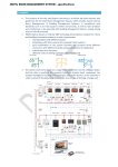
U.motion KNX Server is a web server for monitoring and visualising home & building Automation systems, which have
been realized on the base of the worldwide KNX standard. The configuration and use of U.motion KNX Server takes place
directly through its web interface, which can be accessed through a conventional browser (from any device / operating
system).
This chapter describes how to connect and configure U.motion KNX Server, so that a successful integration into the own
system can occur.
1.2 CONTENT OF THE PACKAGING
The U.motion KNX Server packaging contains the following material:
U.motion KNX Server or U.motion KNX Server Plus
Connector for power supply and KNX bus
Safety notes/General notes
Quick Start Guide
U.motion USB Stick: documentation and software
Hint: U.motion KNX Server is a pure web server and not usable for standalone visualisation, because it has no
display. The visualisation is accessed through client PCs like e.g. the U.motion Client Touch series, which connect via network to the server. The server has no graphical interface (VGA, DVI, HDMI, ...) and therefore can’t
display any graphical contents.
Within this manual the denomination „U.motion KNX Server“ references to both products U.motion KNX Server and U.motion KNX Server Plus, if not named differently in the corresponding text. The differences between
the 2 server versions can be found in the corresponding datasheets, available separately.
-9-
U.motion KNX Server
Installation Manual
1.3 INSTALLATION, CONNECTION AND COMMISSIONING
1.3.1 INSTALLATION AND CONNECTION
U.motion KNX Server is, like most KNX components, mounted on a DIN rail. For a correct function, the following
connections must be guaranteed:
•
Power supply 12V / 24V DC (current consumption 240 mA a 12V) using the supplied connector
•
KNX bus connection via supplied connector
•
Network connection via CAT5 network cable
The LED marked with the label "POWER" on the front of the server signals that the power supply is active, while the
“SERVICE” LED remains off in normal circumstances.
U.motion KNX Server has furthermore the following interfaces:
SD-slot: to expand the memory of U.motion KNX Server with an appropriate SD-card
•
Hint: The actual software version doesn’t support the SD-slot.
Hint: the connection to the KNX bus is not really needed for the configuration of U.motion KNX Server, but it
allows a more efficient programming, since direct tests of the system can be performed.
When commissioning U.motion KNX Server, the following steps must be followed:
Power off the system/installation
Install U.motion KNX Server on a DIN-Rail
Connect power supply and KNX bus to U.motion KNX Server
Power on the system/installation
Wait until U.motion KNX Server has booted up
ATTENTION!
If the U.motion KNX Server hardware is changed, irreversible damage can occur. Any intervention on the
equipment should be performed only by authorized personnel of U.motion KNX Server.
1.3.2 ENVIRONMENTAL CONDITIONS
The correct function of U.motion KNX Server can be granted only if the following requests are met:
OPERATION
Ambient temperature 0°C - 70°C
1.3.3 COMMISSIONING
U.motion KNX Server is power supplied by a power adapter NOT included in the U.motion KNX Server packaging.
The device supports power supply voltages of 12/24V DC.
ATTENTION! Before commissioning U.motion KNX Server all connections must be checked! Verify that the
voltage of the connected power supply doesn’t exceed the supported voltage range, in order to avoid
damage on the device!
- 10 -
U.motion KNX Server
Installation Manual
1.4 NETWORK CONNECTION
For the usage/configuration of U.motion KNX Server a working network connection is required. In order to make the first
access to U.motion KNX Server, or if a compatible network is not available, follow these steps:
•
Connect U.motion KNX Server through a crossed network cable (“crossover-cable”) with your PC
•
Open the network configuration of your PC
•
Change the settings of the TCP/IP – Protocol (Version 4) of the network interface, on which you connected the
network cable and enter the following values:
•
•
IP address: 192.168.0.100
•
Subnet mask: 255.255.255.0
•
Gateway: 192.168.0.110
Save the new settings; depending on the installed OS a restart can be necessary.
The following screenshots show how to change the network settings on Windows XP:
Once the network settings have been changed, open a browser on your PC (Google Chrome preferred) and enter the
following URL into the address bar of the browser:
http://192.168.0.110/umotion/modules/system/externalframe.php?context=configuration
This link will open directly the configuration menu of U.motion KNX Server; if the network connection is working properly
you will see the following screen:
- 11 -
U.motion KNX Server
Installation Manual
Alternatively, you can also just enter the IP address of U.motion KNX Server in the browser address bar. In this case, the
login window of the visualisation is displayed. After login (see next section), the configuration menu can be reached by
clicking on the ADMIN button in the toolbar (more details in the "User manual" or in chapter 1.6 of this manual).
Note: U.motion KNX Server is limited to only one remote access from another PC (Desktop, Laptop), which is
meant for programming the device. The access from mobile devices or U.motion Client Touch 7 through the
U.motion Control-App is not limited!
The maximum comfort for using/programming U.motion KNX Server can be achieved with the following
browsers:
•
Google Chrome
•
Apple Safari
However, it is not recommended to use the following browsers, because they can’t represent all the functions
of U.motion KNX Server correctly:
•
Microsoft Internet Explorer
•
Opera
•
Mozilla Firefox
The browser compatibility is continuously under development, it is recommended to check out the list of the
compatible browsers in the documentation of newly released product versions.
1.5 ACCESS
On delivery U.motion KNX Server has preconfigured the following users:
Username
Password
Description
admin
admin
System Administrator. Can edit the visualisation, create users and change their
access rights / permissions
manager
manager
User for the installation / configuration of the system. It can change all
settings regarding the visualisation, but has no access to system settings.
user
user
Basic user for client-access. It can navigate through the whole visualisation,
but has no or very limited access to the administration of U.motion KNX
Server.
On the first configuration of U.motion KNX Server you must login with the “admin” user. Do this by entering the
appropriate data into the login screen; once logged in you will see the following screen:
- 12 -
U.motion KNX Server
Installation Manual
1.6 ADMINISTRATION AND VISUALISATION AREA
The interface of U.motion KNX Server is split into two areas:
•
“ADMINISTRATION” or “BACKEND”: Configuration area, in which (depending on the users permissions) each
aspect of the web server and visualisation can be modified
•
“VISUALISATION”: Visualisation area, designed for being used by the final user. It allows to navigate inside the
single rooms/pages of the visualisation, which were configured in the ADMINISTRATION before, and controlling
KNX objects in real-time
Both areas are based on web technology and can therefore be controlled from within a browser window. The main
difference between the two levels is the graphical design:
•
The ADMINISTRATION is kept in a simple graphic
style and was optimized to represent the maximum
amount of information and option windows in a
clear form.
•
The VISUALISATION was designed to allow the
inexperienced users the most intuitive and easy
navigation. The high-end design of the
VISUALISATION makes it very comfortable for the
final customer to use the visualisation.
To switch between the two areas the appropriate button in the current areas can be used:
•
From within the ADMINISTRATION it is possible to reach the VISUALISATION by clicking on the respective
button in the upper right corner
•
From within the VISUALISATION it is possible to reach the ADMINISTRATION by clicking the entry “ADMIN” in
the upper right menu (only accessible if the toolbar is extended); of course the user must have the permissions
to access the ADMINISTRATION (further information can be found in the „User manual”).
Alternatively the two areas can be accessed directly by entering the following links inside the browsers address bar:
LEVEL
EXAMPLE
ADMINISTRATION http://192.168.0.110/umotion/modules/system/externalframe.php?context=configuration
VISUALISATION
http://192.168.0.110/umotion/modules/system/externalframe.php?context=runtime
- 13 -
U.motion KNX Server
Installation Manual
To save time during configuration, both areas can be displayed simultaneously in different tabs of the browser,
which makes it faster to switch between the areas.
1.7 RESET OF THE IP ADDRESS
The IP address of U.motion KNX Server can be reset to factory settings through the RESET-button on the bottom side of
the device:
•
Localize the RESET-button on the device and get a screw driver or a similar tool with a small diameter to reach
the RESET-button through the small cutout in the housing of the device.
•
Press the RESET-button until the SERVICE-LED starts blinking (minimum 10 seconds); afterwards release the
RESET-button.
•
Press the RESET-button again within the next 5 seconds for max. 1-2 seconds and release the RESET-button
afterwards; after a short pause the SERVICE-LED stays on for some seconds.
•
AS soon as the SERVICE-LED turns off, U.motion KNX Server is reachable under the factory-IP address
(“192.168.0.110”)
If the SERVICE-LED stops blinking after the RESET-button was pressed for the first time (10 seconds) and before you were
able to press the RESET-button again, please repeat the whole procedure.
1.8 RESET TO FACTORY SETTINGS
U.motion KNX Server can be reset to factory settings (IP address & database) through the RESET-button on the bottom
side of the device:
•
Localize the RESET-button on the device and get a screw driver or a similar tool with a small diameter to reach
the RESET-button through the small cutout in the housing of the device.
•
Press the RESET-button until the SERVICE-LED starts blinking (minimum 10 seconds); afterwards release the
RESET- button.
•
Press the RESET-button again within the next 5 seconds and keep the button down until the SERVICE-LED stops
blinking and stays on; afterwards release the RESET-button.
•
AS soon as the SERVICE-LED turns off, U.motion KNX Server is reachable under the factory-IP address
(“192.168.0.110”) with empty database (factory settings).
If the SERVICE-LED stops blinking after the RESET-button was pressed for the first time (10 seconds) and before you were
able to press the RESET-button again, please repeat the whole procedure.
- 14 -
U.motion KNX Server
Installation Manual
2 GENERAL OVERVIEW
2.1 INTRODUCTION
This chapter gives an overview of the ADMINISTRATION area of U.motion KNX Server and explains different tools and
menus, which can be used to configure the web server.
2.2 ADMINISTRATION AREA - INTERFACE
The ADMINISTRATION is divided into the following sections:
SEARCH-FUNCTION
The search function can be found in the upper left corner in form of an input filed, which
allows to find objects quickly by entering keywords related to the searched objects.
MENU
Main menu of the software, shown as a tree-view. Through this menu all sections of the
software are accessible and objects can be created / modified / deleted.
TOOLBAR
The toolbar in the upper side of the ADMINISTRATION is always shown and allows
switching quickly to the mostly used functions through the related buttons.
WORKSPACE
Main area for showing the chosen configuration options; the single menus and
configuration windows of the objects are shown in here. It is possible to open more
menus / windows in the main area at the same time; the different menus / windows will
be accessible through different tabs in this case.
- 15 -
U.motion KNX Server
Installation Manual
The following screenshot shows the single sections of the ADMINISTRATION area:
Toolbar
Search function
Workspace
Menu
2.3 TOOLBAR
Following functions are always present in the toolbar:
SAVE
Allows saving all changes into the flash memory of U.motion KNX Server, what will preserve
the data even if the web server is powered off. The button turns red whenever changes are
made, but not saved yet. In addition, every 5 minutes an automatic saving of all changes
takes place, so pressing the “SAVE”-button is only necessary if the system should be shut
down/restarted immediately after making the changes.
CLEAR CACHE
Allows to delete the HTML SERVER CACHE. This is especially necessary if changes made in
the ADMINISTRATION are not displayed correctly in the VISUALISATION, despite the HTML
CLIENT CACHE was already deleted.
BASE / EXPERT
Changes the visibility of various options / parameters within the configuration pages. The
BASE mode displays only the necessary settings and visible objects; the EXPERT mode,
however, shows even more advanced options as well as hidden objects.
LOGOUT
Ends the current session and allows you to log onto the web server as a different user.
VISUALISATION
Allows switching to the VISUALISATION area and therefore accessing the visualisation, now
showing all modifications made in the configuration.
- 16 -
U.motion KNX Server
Installation Manual
2.4 NAVIGATION MENU
2.4.1 USAGE
The navigation menu is a typical tree-view-menu. After accessing the ADMINISTRATION area all the main entries are
shown; the sub-menus are accessed by extending the corresponding main menu. The navigation in this menu is done
entirely with a mouse.
Clicking on an entry in the navigation menu turns the clicked entry into grey; if the entry has additional submenus, the
entry will be extended and the sub-menus are displayed. Another click on the selected entry will close the section and
hide the submenus again.
If actions can be performed for the selected entry, they will be displayed in the TOOLBAR at the bottom left corner of the
navigation menu in form of different buttons. The following actions may be displayed:
NEW / ADD
Allows the creation of a new object within the selected entry. Depending on the selected
item different types of objects are created; if a menu allows the creation of multiple types
of objects, then a context menu will be displayed in order to select the object type to
create.
DELETE
Deletes the selected entry from the project
EDIT
Allows editing of the selected entry though the appropriate configuration window, which
will be opened automatically by clicking this button.
CLONE
Creates an identical copy of the object
- 17 -
U.motion KNX Server
Installation Manual
When an object is cloned, not only the objects itself is duplicated, but also all of its connections / relations
with other objects. This means that the cloned object will be contained in the same rooms, logics, scenarios
etc. as the original object is. Therefore, after the creation of a cloned object, all relations and connections
should be checked and if necessary corrected.
Note: if the original object was present in a room with BACKGROUND view, the cloned object will be
positioned AT THE SAME PLACE in the room and will cover the original object. In this case, please edit the
BACKGROUND view and place the cloned object in a different position.
If the selected entry supports the EDIT-action, 3 points (“…”) will be displayed on the right side of the entry. Clicking on
these points has the same effect as clicking on the EDIT button in the TOOLBAR.
If the configuration window of an entry is opened through the EDIT-action, the entry will show an arrow-icon instead of 3
points (“…”) on the right side. This icon will be displayed until the configuration window of the entry is closed and shall
facilitate the navigation if multiple tabs are opened in the workspace.
- 18 -
U.motion KNX Server
Installation Manual
As mentioned before, some of the entries of the navigation menu permit to create submenus or to insert new objects.
This is done using the NEW button in the TOOLBAR: by pressing this button a new object (the object type depends on
the selected entry) will be created and selected automatically. If the EDIT button (or the 3 points in the entry itself) is
clicked, the configuration window of the newly created object will be opened.
Example: To create a new room, just select the entry "ROOMS" (in the main menu "VISUALISATION") and click on the
NEW button. The new room will be created and - if other rooms have already been created before - shown at the end of
the sub-menu:
- 19 -
U.motion KNX Server
Installation Manual
For rooms it’s also possible to create further sub-menus following the same procedure (as in the further course of this
manual will be explained); the resulting tree-structure can so also be used in the visualisation.
The DELETE button removes the selected entries from the project. This action is blocked for the system menus and
indispensable objects, for preventing the user to remove them by accident.
2.4.2 MENU STRUCTURE
The navigation menu permits to access every setting of the web server and has the following structure:
SETUP
Contains generic settings and parameters of the web server
TECHNOLOGIES
Contains the configuration pages of all technologies supported by the web server (KNX.
Video surveillance, intercom etc.)
CUSTOMIZATION
Contains the configuration pages for customizing the graphical design of the
visualisation and the web server plugins
VISUALISATION
Allows the configuration of the visualisation itself (rooms, functions, scenarios etc.)
ADVANCED FUNCTIONS
Allows the configuration of additional functions (e.g. logics, notifications etc.)
USERS AND PERMISSIONS
Allows the configuration of new users and their access permissions
2.4.3 SETUP
The menu SETUP contains the following entries:
LANGUAGE
Permits to change the language of the GUI
NETWORK
Permits to configure the network parameters of U.motion KNX Server
UPDATE
Permits to update the web server through specific update-packages
BACKUP/RESTORE
Permits to create a backup of the current database, to import an already created backup
or to reset the database to factory settings
DATE/TIME
Permits to configure date/time of the web server and all date/time related settings
Further information can be found in the appropriate section of this manual.
2.4.4 TECHNOLOGIES - KNX
This section contains all settings for establishing a communication with the KNX bus:
ETS-IMPORT-RULES
Permits to configure import-rules, through which the imported group addresses will
automatically be configured and connected to the desired icon/function, in dependence
of the defined keywords
ETS IMPORT
Allows the import of a ETS-project into U.motion KNX Server
CONFIGURE
COMMUNICATION
Permits to change the parameters of the used KNX communication interface
ETS PROJECT
Permits to navigate through the single group addresses and to edit them; the navigation
structure will be the same as the one in ETS.
- 20 -
U.motion KNX Server
Installation Manual
2.4.5 TECHNOLOGIES – VIDEO SURVEILLANCE
In this section IP cameras can be integrated into the visualisation; they can be reached inside the visualisation by clicking
on the related icon in the navigation menu.
2.4.6 TECHNOLOGIES – INTERCOM (ONLY U.MOTION KNX SERVER PLUS)
This section contains several configuration menus for using U.motion KNX Server Plus as VoIP server (for the integration
of door communication systems):
VOIP participants
IP phones or softphones (with SIP protocol support)
EXTERNAL UNITS
Compatible video or audio door stations (SIP-Protocol support is necessary, supported
video format: MJPG )
CALL GROUPS
External and internal units can be grouped into a call group; by calling a call group, all the
internal and external units belonging to the call group will start ringing.
CLIENTS
Here are all client objects listed, which can be used for Intercom communication
USER
Here are all user objects listed, which can be used for Intercom communication
SETTINGS
Generic parameters of the SIP server configuration
2.4.7 TECHNOLOGIES – ENERGY
This section allows monitoring and control loads:
CONSUMPTION
Representation of the energy consumption of loads, even in graphical form
LOADS
Control of loads depending on the overall power consumption (power consumption
optimization)
IMPORT/EXPORT
Import/Export of recorded data
2.4.8 CUSTOMIZATION
This section contains the following entries:
THEMES
Permits to change the design (theme) of the VISUALISATION
NAVIGATION MENU
Permits to personalize the navigation menu of the VISUALISATION
FAVOURITES
Permits to change the favourites page of the VISUALISATION
OPTIONS
Allows the configuration of several aspects / plugins of the VISUALISATION
Further information about customization can be found in chapter 4 of this manual.
2.4.9 CUSTOMIZATION – NAVIGATION MENU
This entry permits to customize the navigation menu of the VISUALISATION area. Existing entries can be hidden (only
possible in EXPERT mode) and also rooms (see next section) can be added to the navigation menu. Therefore, proceed as
described below:
•
Open the settings window of the entry NAVIGATION MENU by clicking the 3 points or the EDIT button
•
Search the desired room by using the search function (see chapter 2.5 for further information about the
search function)
•
Drag the selected room inside the configuration window of the navigation menu and drop it there
In this way rooms can directly be added into the navigation menu and so they are visible in the home screen inside the
navigation menu (and also directly in the main page of the VISUALISATION, if this option is active). Furthermore, any
- 21 -
U.motion KNX Server
Installation Manual
system entry access, which is not desired, can be easily hidden from the navigation menu; in this way the VISUALISATION
can be directly adapted to the customer’s needs.
2.4.10
VISUALISATION - ROOMS
This section allows the configuration of the rooms inside the visualisation. This section is initially empty and allows the
creation of new rooms (from a technical point of view objects of type "GROUP"), which can contain other rooms or other
objects supported by U.motion KNX Server.
For each room a so called Template can be selected. Depending on the selected THEME different Templates are available.
Currently the following Templates are available:
BACKGROUND
Background image (photo, graphic rendering, plan), on which the single control objects
are positioned. Clicking on such a control object, it either sends the related command on
the KNX bus or opens a box containing further control options.
GRID
Shows the contained objects in table-form. Depending on the type of object, it can be
controlled directly by clicking on the related buttons of the object or a pop-up window is
opened with additional controls, when the object is clicked.
Image:
•
FULLSCREEN
•
ON TOP
•
ON RIGHT
•
ON LEFT
The grid may also include an image file that is positioned depending on the selected
template.
If the entry ROOMS is selected directly and its configuration window is opened by clicking on the EDIT button,
the order of the contained rooms can be changed. Since this group belongs to the system, no other settings
are available.
2.4.11
VISUALISATION - FUNCTIONS
This section allows the organization of the FUNCTIONS, which group the KNX objects automatically based on their
typology. If an object is for example linked with the FUNCTION "Illumination", it is automatically copied into the group
"Illumination" of the FUNCTIONS. This group can be called directly in the VISUALISATION, providing quick access to the
objects of the same typology.
After activating the EXPERT-mode (see chapter 2.3) through the appropriate button in the toolbar, for each FUNCTION it
can be defined whether it should be visible in the VISUALISATION or not:
- 22 -
U.motion KNX Server
Installation Manual
Furthermore, the order of the single entries can be changed. Click on the grey ORDER-button of an entry, drag it up or
down to the desired position and drop it there to fix the entry in the new position. The new sequence is shown in the
VISUALISATION after accessing the FUNCTIONS menu again.
Further information can be found in chapter 7 of this manual.
2.4.12
VISUALISATION – LINKS
This section allows the configuration of links. Using these objects you can create page jumps to other rooms of the
visualisation or even to external web contents (like the contents of a web server or a homepage).
Further information can be found in chapter 10 of this manual.
2.4.13
VISUALISATION - SCENARIOS
This section allows the configuration of scenarios. With scenarios, multiple actions can be launched sequentially- if
necessary also time delayed – with only one click. Scenarios can also be started as a passive event by other objects or via
scheduling.
The order of the single scenarios can be changed by opening the configuration menu of the SCENARIOS entry and by
moving the single scenarios to the desired position through drag and drop. In EXPERT mode it is also possible to define
for each scenario if it should be visible in the VISUALISATION or not.
Further information can be found in chapter 9 of this manual.
2.4.14
VISUALISATION – COMPLEX OBJECTS
This section allows the configuration of so-called complex objects, in which KNX objects of the same device can be
grouped and therefore will be accessible and operable in one of the available templates (for example: thermostats, blinds,
dimming, RGB control, etc.). For more information, refer to chapter 8 of this manual.
2.4.15
ADVANCED FUNCTIONS
This section permits to extend the system with functionalities that are not programmed on KNX level. The following
advanced functions are available:
LOGICS
Allows AND/OR operations on 1bit KNX-objects
CONDITIONS
Permits to compare a value of one or more objects with a fixed value and to define events,
which are launched in dependency of the comparison result
VIRTUAL OBJECTS
Permits to create virtual objects for example for saving values, for connecting passive and
active events etc.
INTEGRATORS
Permits to observe / evaluate values over a given time period; specially convenient for
evaluating energy-values
NOTIFICATIONS
Permits to send notifications (either “on screen” or via mail) in dependency of events
within the installation
CLIENTS
Permits to create relations between the devices connected to U.motion KNX Server (each
connected device will be shown as CLIENT) and different actions of the software, like e.g.
scenarios, VoIP actions, …
- 23 -
U.motion KNX Server
Installation Manual
2.5 SEARCH FUNCTION
By entering one or more keywords into the search box in the upper left corner, the software searches for all objects, which
include the specified keyword in their names or other primary properties. The results are displayed in the left area instead
of the navigation menu, which is minimized for this purpose:
The results are shown together with the following information:
NAME
Name of the object inside the software’s database
TYPE
Object-type; shown directly under the name of the object
PRIMARY PROPERTY
If available, on the right side the primary property of an object is shown (for example: the
group address of a KNX object)
By setting a search filter, only relevant object types are displayed in the search result. Search filters can be activated by
clicking on the corresponding description in the properties of an object. If, for example, a search filter for KNX group
addresses is active, only objects of type "KNX group address" matching the specified search word are displayed in the
search results. By clicking on the FILTER-icon to the right of the search box, such a search filter can be disabled.
A result entry will be colored green if it is clicked; as within the navigation menu, there will appear some action buttons in
the bottom toolbar, if the selected object allows editing. In this case, the 3 points on the right side of the selected entry
will be visible, enabling a quicker access to the property window.
It is possible to change the objects name directly in the search engine with a simple double click on the whished item in
the list of search results.
This way the search engine can be used to do fast customizations.
The search function also supports the multiple selection of objects by holding the CTRL key of your keyboard while
selecting the desired objects with the mouse. The selected objects will all be colored green:
- 24 -
U.motion KNX Server
Installation Manual
The TOOLBAR can show the following action buttons:
EDIT
Opens the configuration window of the selected objects
DELETE
Removes the selected objects from the project
CLONE
Clones the selected objects
The CLONE-action creates a one-on-one copy of the selected objects. After the execution of this command, the search
results are refreshed and also the cloned objects will be shown (can be recognized from the prequel “Copy of ...”).
When cloning an object, not only the objects itself is duplicated, but also all of its connections / relations with
other objects This means that the cloned object will be contained in the same rooms, logics, scenarios etc. as
also the original object. Therefore, after the creation of a cloned object, all relations and connections should
be checked and – if necessary – corrected.
Note: if the original object was present in a room with BACKGROUND view, the cloned object will be
positioned AT THE SAME PLACE in the room and will cover the original object. In this case, please edit the
BACKGROUND view and place the cloned object in a different position.
2.6 WORKSPACE
2.6.1 OVERVIEW
The WORKSPACE is the working surface of the ADMINISTRATION area. It offers the possibility to open several
configuration windows at the same time in different tabs. The configuration window of a selected entry will be opened
when the EDIT-action (either the 3 points of the selected entry or the EDIT button in the TOOLBAR) is executed.
- 25 -
U.motion KNX Server
Installation Manual
2.6.2 USAGE OF THE TABS
All opened tabs are displayed in the TAB-BAR of in the upper area of the WORKSPACE:
If a large number of tabs is opened, they are not all represented in the TAB-BAR. The hidden tabs can be accessed
through the button at the right end of the TAB-BAR, which on click shows a complete list of all opened tabs. To close an
opened tab, move the mouse pointer on the tab title and close the tab through the appearing X-icon. If there are present
any unsaved changes in the tab, you will be informed about it before the tab is closed, in order to avoid data loss.
2.6.3 HELP
A click on the help button (?) opens a pop-up with information about the current WORKSPACE content:
When you switch into another tab, the help pop-up will be closed. For showing the help of the new tab, click the help
button again.
- 26 -
U.motion KNX Server
Installation Manual
3 SETUP
3.1 INTRODUCTION
This chapter explains the configuration pages for installation, commissioning and maintenance of U.motion KNX Server.
All sections and menus described in this chapter can be found in the SETUP section of the navigation menu. To have
access to all of these settings, you must be logged in as administrator.
3.2 LANGUAGE
This page allows the configuration of the language that should be used for the different areas of U.motion KNX Server.
Currently the language can be set separately for the ADMINISTRATION and VISUALISATION area. Select the desired
language for the appropriate area and click on "SAVE". Once the storage procedure is completed, the page will be
refreshed and displayed in the selected language.
- 27 -
U.motion KNX Server
Installation Manual
3.3 NETWORK
This page allows the configuration of the network parameters of U.motion KNX Server:
The available parameters are:
IP ADDRESS
IP address of U.motion KNX Server; this address must be present in the network only
once and must be compatible with the IP addresses of the other devices inside the
same network (if unsure, please contact your network administrator)
SUBNET MASK
If no special network configuration is used, don’t change the standard value
“255.255.255.0”
GATEWAY
Enter the IP address of your router (if present) or the referenced server of the
network (if unsure, please contact your network administrator).
NOTE: in order to guarantee remote access to U.motion KNX Server, you must enter
the IP address of the Internet router, through which you want to access the web
server. For more details, see the appropriate section of this manual.
PRIMARY DNS
SECONDARY DNS
DNS addresses over which U.motion KNX Server can access the internet (if available).
If no connection is possible with the default addresses, please contact your network
administrator.
After modifying the single parameters, please click on "SAVE". If the IP address was changed, the new IP address must be
entered in the address bar of the browser for reconnecting with the webserver. Please ensure that all entered data is
correct before you save them. If incorrect settings are saved, U.motion KNX Server will probably be no longer accessible
through the network.
- 28 -
U.motion KNX Server
Installation Manual
3.4 UPDATE
This menu permits to update the software version of U.motion KNX Server; please use only official update packages
published by the manufacturer, in order to avoid malfunctions. To update U.motion KNX Server, please proceed as
follows:
•
1
Save the update package (downloaded from homepage or received via mail) on your PC without unpacking it
•
•
Open the UPDATE menu in the ADMINISTRATION of U.motion KNX Server
•
Choose the update package through the button “Choose file” (or similar, depends on the browser)
•
Check if the update package includes a newer version of the software (current version is shown on top)
•
Click on the button “UPDATE”
The update process runs completely automatically; please wait for feedback from the page without performing other
tasks or exiting the browser (risk of data loss / web server malfunction). Depending on the configuration and software
version, the update may take several minutes.
Once the update process is completed, a brief summary as well as the new software version is displayed. To complete the
update, please click on the "Restart now" button, which will restart the operating system of U.motion KNX Server.
3.5 BACKUP/RESTORE
This page allows the creation of a backup of your project, or also the import of a previously created backup (even from
another U.motion KNX Server or the U.motion Builder).
1
HINT FOR MAC-USERS: if the update package is downloaded with SAFARI or the integrated mail client, it will be
unpacked automatically, which prevents a successful update. In this case, please download the update package again
using an alternative browser / email client.
- 29 -
U.motion KNX Server
Installation Manual
In addition, U.motion KNX Server can be reset to factory settings (the IP address will NOT be affected by the reset).
After the desired action has been selected (and in case of the import action a suitable backup has been selected), click on
"EXECUTE" and wait for the desired action to be processed. Neither cancel the started action nor close the browser
window during this process.
3.6 DATE/TIME
This page allows setting several parameters related to date and time of U.motion KNX Server.
3.6.1 DATE/TIME CONFIGURATION
Permits to manually adjust the system time of the web server. If in the own ETS project at least an object of type date or
time is available, U.motion KNX Server can be configured to send these values automatically on the bus to synchronize
other devices with its date and time.
3.6.2 TIMEZONE SETTINGS
Allows configuring the time zone in which U.motion KNX Server is located.
3.6.3 ONLINE UPDATE
Allows defining a time server and a time interval to update automatically the system time; if no special settings are
required, it is recommended to use the default settings.
3.6.4 SCHEDULED SERVICES REBOOT
Provides an automatic restart of the services running on U.motion KNX Server in the background; week day and time for
the automatic restart of the services can be configured here. Normally, the automatic restart of the services is not
required, therefore it is recommended to not change the factory settings.
- 30 -
U.motion KNX Server
Installation Manual
4 CUSTOMIZATION
4.1 THEMES
U.motion KNX Server offers different themes for changing the design of the VISUALISATION; in this page one can choose
which theme should be used for the VISUALISATION of U.motion KNX Server:
- 31 -
U.motion KNX Server
Installation Manual
4.2 NAVIGATION MENU
This page permits to personalize the navigation menu. The individual links can be defined, as well as their order within
the navigation menu itself. If the EXPERT mode is active, all personalization options of the navigation menu are accessible:
Through the option "VISIBLE" the individual menu items for the navigation menu can be activated or hidden; all hidden
menu items are displayed semi-transparent and are not visible in the navigation menu. Menu items of the system itself
can’t be deleted, but only hidden.
To change the position of a menu item, it can be moved through "drag and drop" using the grey ORDER button, as
already explained for other objects.
It’s also possible to add rooms to the navigation menu so that they are directly accessible from the navigation menu and
the HOME page. This can be done by searching the desired room with the search function and pulling them into the list
("drag and drop").
Once the visualisation is refreshed, the changes made in the navigation menu will be visible.
4.3 FAVOURITES
All objects that in the visualisation have been identified as "FAVOURITES" can be managed here. On delivery this list is
empty. The end user can define various objects in the VISUALISATION as "FAVOURITES" on his own, which results that the
defined objects will be automatically included in the list shown below. The “FAVOURITES” are reachable either through
the navigation menu or through the HOME page.
- 32 -
U.motion KNX Server
Installation Manual
In this configuration window the list with the favourites can be modified:
•
Objects can be deleted from the list with the DELETE button
•
The order of the single objects can be changed by dragging them (using the grey ORDER button) to the desired
position in the list and dropping them there.
◦
New objects can be added by dragging them in directly from the search function
4.4 OPTIONS
In this configuration menu the basic customization of the VISUALISATION of U.motion KNX Server can be realized.
4.4.1 HOME
This menu allows the customization of the graphical interface of the HOME page. The HOME page may contain different
information from the system, the local weather forecast and different information from the created visualisation; the
background image is also customizable:
SHOW CURRENT TEMPERATURE
This option embeds the local outside temperature into the HOME page;
the forecast information for the defined location are set in the menu
“WEATHER”
SHOW WEATHER FORECAST
Enables/Disables the weather forecast for the next 2 days
USER WEATHER INFO AS BACKGROUND
Enables/Disables the adaption of the HOME page’s background in
dependency of the actual weather information.
BACKGROUND IMAGE (IF NOT WEATHER)
Alternatively to the already mentioned options, a static image can be
defined as background image of the HOME page.
CLOSE NAVIGATION MENU AUTOMATICALLY Enables/Disables the automatic closing of the navigation menu
- 33 -
U.motion KNX Server
Installation Manual
4.4.2 MAIL
This section allows configuring all parameters required for sending mails through U.motion KNX Server:
SMTP SERVER
SMTP-Server for sending mails
USERNAME
Username for accessing the SMTP server
PASSWORD
Password for accessing the SMTP server
ACTIVATE AUTHORIZATION
Defines whether for the communication with the SMTP server a user
authentication is required or not
FORWARDER (MAIL ADDRESS)
Mail address of the sender; will be shown in the sent mail as address
from which the mail comes from
PORT
Port for the communication with the SMTP server
USE SSL PROTOCOL
Defines whether the SSL protocol shall be used for the communication
with the SMTP server or not.
4.4.3 NOTIFICATIONS
This page permits to configure the behavior of U.motion KNX Server at incoming notifications, depending on their type /
priority level. For each type you can define whether the notification central should automatically pop up or just an advice
should be shown in the HOME screen / navigation menu.
At default settings, only at incoming ALARM notifications the notification central is automatically opened.
4.4.4 WEATHER
In this menu the location, for which the weather data should be displayed, can be defined. Simply specify the name of the
location, province, region or zip code, as required by the used weather service (WORLD WEATHER ONLINE,
www.worldweatheronline.com ).
Hint: Please do not use commas to separate the data, since the weather service doesn’t support that. Please
use spaces to divide the single words / numbers.
The usage of the weather services requires a valid “Weather API ID”, which can be obtained for free on the following web
page:
http://free.worldweatheronline.com/register.aspx
Without valid Weather API ID the weather services of U.motion KNX Server can’t be used. In this case,
please disable all kind of weather information / display within the HOME page, as described within the last
chapters.
4.4.5 RSS FEEDS
Up to 5 RSS feeds can be integrated into the visualisation; through the appropriate link in the navigation menu, the page
displaying the specified RSS feeds can be reached. For each feed a title and the appropriate URL can be specified:
- 34 -
U.motion KNX Server
Installation Manual
Parameter
Value
Feed 1 - Title
BBC
Feed 1 - URL
http://feeds.bbci.co.uk/news/rss.xml
Feed 2 - Title
Sports
Feed 2 - URL
http://feeds.bbci.co.uk/sport/0/rss.xml?edition=uk
The following screenshot shows the result of a correct configuration of the RSS feeds:
To get the appropriate feed URL check out the homepage of the provider of the feed. If the corresponding
URL is not already listed, but only a link to the RSS feed is available, you can get the URL through the context
menu (right-clicking on the link) by selecting the option "Copy address"; the link address will be copied to the
clipboard and from there it can be easily pasted into the configuration of U.motion KNX Server.
Note: Not all RSS feeds are necessarily compatible with the XML encoding used by U.motion KNX Server and
therefore may not be shown correctly.
4.4.6 INTERNET BOOKMARK
In this page a bookmark for the integrated browser function can be defined; this page will be shown when the internet
bookmark function inside the VISUALISATION is accessed (through the navigation menu).
Hint: The web browser integrated inside the VISUALISATION area is not compatible with all web pages. All
pages that use an automatic forwarding to other sites can’t be handled properly. As the name of this
functionality indicates correctly, it was designed to configure and open single internet bookmarks and not for
complete navigation.
- 35 -
U.motion KNX Server
Installation Manual
4.4.7 DISPLAY-INTERACTION
This page contains different options regarding the usage / interaction of the software on client devices. The following
options are currently available:
ON-SCREENKEYBOARD
(LOCAL
REMOTE)
&
CLEANING
MODE
(LOCAL
REMOTE)
Permits to enable – both locally (U.motion Builder, U.motion KNX Server) or remote via network – an onscreen-keyboard, through which it is possible to make text inputs within the software even on touch
devices that don’t have an own soft- or hardware keyboard.
&
Permits to enable – both locally (U.motion Builder, U.motion KNX Server) or remote via network – a
special button within the TOOLBAR of the VISUALISATION; by clicking on this button, a cleaning page will
be shown that blocks any interaction with the software for 30 seconds and therefore permits to clean the
touch display avoiding the risk of unwanted clicks within the visualisation.
4.4.8 ADVANCED
This page contains the options for the Cache technologies, which are used on U.motion KNX Server. These caching
technologies accelerate the navigation inside the VISUAISATION, because the needed data is loaded on the first access
on the local storage of the used client. On every next access the data is already available in the local cache and the
VISUALISATION can be used without any mentionable delays. Additional also the refresh rate for the status of the objects
in the present inside the VISUALISATION can be set. The following options are here available:
Enable cache HTML client
Enables the first synchronization of HTML content in the browser (on the first access with
a new browser window). This accelerates every next access even when the browser gets
closed.
HINT: The HTML client cache can be deleted on U.motion KNX Server by restarting the
device.
Enable cache HTML server
Enables saving of often user pages on the U.motion KNX Server to accelerate future
access from other devices (PC/mobile devices).
Enable DB client cache
Enables saving of different data in the browser cache during the navigation in the
VISUALISATION to accelerate future navigation.
It is recommended to activate the cache technologies. If the cache technologies are enabled, the
VISUALISATION reacts nearly in real-time. Only trained personal should change these setting.
- 36 -
U.motion KNX Server
Installation Manual
5 KNX
5.1 INTRODUCTION
The following chapters will show in detail how U.motion KNX Server has to be configured in order to work in a KNX
system. Prerequisite for creating the VISUALISATION on U.motion KNX Server is a KNX project that has been
programmed either with ETS3 or ETS4. The focus of the subsequent chapters is initially on how the individual data points
are imported and what options for these data points are available. The creation of the graphical interface of the
VISUALISATION will be explained in chapter 6, "Rooms".
5.2 REQUIREMENTS AND EXPORT OF THE ETS PROJECT
U.motion KNX Server allows the import of KNX projects that have been realized with ETS3 or ETS4. U.motion KNX Server
automatically takes over the structure and functionality of the single group addresses contained in the ETS project; the
entire import process only takes a few minutes. To import a ETS project into U.motion KNX Server it is required that the
project is available in a compatible format.
5.2.1 OPC-IMPORT
With the OPC export of ETS it is possible to create a compatible project file directly out of ETS. This file can be used to
import the needed information of the ETS project into U.motion KNX Server.
Open the ETS software
Open the desired project, which should be imported into U.motion KNX Server
Execute the OPC export to create a file with the ending *.esf (ETS3: “Data exchange” -> “Export to OPC-SERVER”;
ETS4: “Extras” -> “OPC export”)
- 37 -
U.motion KNX Server
Installation Manual
5.3 ETS IMPORT RULES
Before the KNX project is imported into U.motion KNX Server, you should just think about the usage of the ETS import
rules. The administration of the ETS import rules can be found in the ADMINISTRATION of U.motion KNX Server under
"TECHNOLOGIES" → "KNX":
The ETS-import rules automate the import process by assigning function and graphical appearance to the single data
points depending on the configured criteria. The available criteria are data type (length), encoding and user-definable
keywords which have to be included in the name of the group addresses for whom the corresponding ETS import rule
should be applied. In U.motion KNX Server some ETS import rules, which apply to generically used data points, are
already predefined; adjusting the ETS import rules is worthwhile, since it will make the personalization of a lot of data
points after the import no more necessary.
Following parameters can be defined:
KEYWORD
One or more keywords, of which at least one must be present in the name of a group address
of the imported KNX-project, so that the ETS import rule will be applied correctly. When
multiple keywords are specified, they must be separated by a comma; blank spaces are
recognized as part of the keyword!
TYPE
Length (in bit/byte) of the target group addresses in the KNX project
ENCODING
Encoding to be used by U.motion KNX Server in order to interpret the KNX bus data correctly;
the available encodings depend on the data length defined in "TYPE"
FUNCTION
During the import process U.motion KNX Server, for each group address present in the KNXproject, creates a KNX object in its internal database. Each KNX object, created from a group
address for which an ETS import rule was applied, will be automatically assigned to the here
defined FUNCTION category during the import process
SYMBOL
Icon for showing the object graphically inside the VISUALISATION, assigned automatically by
the defined ETS import rule
- 38 -
U.motion KNX Server
Installation Manual
The ETS import rules are used by U.motion KNX Server as follows: during the import process, all group addresses within
the import file are scanned and for each address a KNX object is created. If at least one of the keywords defined in an ETS
import rule is found in the name of a KNX object, U.motion KNX Server checks whether the data length of this object
matches the one defined in the ETS import rule ("TYPE"). If this second parameter matches, the ETS import rule is applied
for this KNX object. For the matching KNX object the encoding defined in the ETS import rule will be applied
automatically, furthermore it will be assigned to the FUNCTION category defined in the ETS import rule and also it will
get the symbol specified in the rule. Any further editing of KNX objects, which have already been customized by an ETS
import rule, is normally not needed, what can save a lot of time.
All KNX objects, which do not match at least one ETS import rule, must be edited manually during or after the import
process, in order to assigning data length, encoding and the icon. Especially for large ETS projects with numerous group
addresses it is recommended to make use of the ETS import rules, since the manual configuration of the single KNX
objects can take a lot of time depending on the number of KNX objects.
The ETS import rules can be modified also during the import process, in the moment when those KNX objects
are listed, which do not match with any ETS import rule.
5.4 ETS IMPORT
For being able to import an ETS project, it must be first created a compatible project file for U.motion KNX Server like
described in 5.2. The import process for U.motion KNX Server is the following:
•
Open the ADMINISTRATION menu
•
Under “TECHNOLOGIES“ → “KNX“
•
Select (through the “BROWSE“ button) the project file you created
•
Configure the import options as desired and click “NEXT” for starting the import procedure
choose “ETS IMPORT”
- 39 -
U.motion KNX Server
Installation Manual
In BASE mode the following options are available:
DELETE EXISTING KNX-OBJECTS
If this option is enabled, all KNX objects present in the database will be
deleted before the ETS-Import.
CREATE AUTOMATIC RELATIONS
This option enables / disables the automatic recognition of relations
between individual group addresses in the ETS-project and the creation of
the same relations in the U.motion KNX Server database, for example for
updating statuses of individual objects across multiple group addresses (e.g.
for central functions).
Enabling this option usually results in a correctly functioning and always
refreshed visualisation. If manual changes to the relations between KNX
objects and group addresses have been performed in the U.motion KNX
Server database, it is better to disable this option, otherwise all manual
changes will be overwritten. More details about modifying relations between
KNX objects and group addresses can be found in the following chapter.
SELECTIVE IMPORT
This option allows to select the single group addresses to import.
Note: This option is enabled automatically when the ETS-project to be
imported contains more group addresses than the license of U.motion KNX
Server allows.
The EXPERT mode shows additional options for the ETS import:
REMOVE NONEXISTING KNX OBJECTS
If this option is enabled, all previously imported KNX objects that aren’t
present in the new ETS project anymore will be deleted from the U.motion
KNX Server database.
REFRESH NAMES
If an existing U.motion KNX Server database is updated, two options define
whether the names and the read/write flags of the KNX objects within this
database should be adapted to the new names and flags from the ETS
project or not.
REFRESH ETS FLAGS
These options should not be enabled if there have been made changes on
KNX objects in the U.motion KNX Server database, independently from ETS
project
COMMUNICATION INTERFACE
The interface, through which U.motion KNX Server communicates with the
imported KNX group addresses, can be selected here. If no special
configurations in U.motion KNX Server have been made, only the integrated
KNX interface is available.
By clicking "NEXT" the import process is started, which will last a few minutes depending of the size of the ETS project to
import. U.motion KNX Server will automatically create the appropriate KNX objects which can be used to create the
graphical visualisation. Once the import process is finished, a summary of all actions is shown:
- 40 -
U.motion KNX Server
Installation Manual
As soon as the project is imported, U.motion KNX Server checks if the single KNX objects are matching an ETS import
rule. If for a KNX object at least one ETS import rule is matching, it will be applied; no additional configuration of these
objects will be necessary.
If all created KNX objects match at least one ETS import rule, after some seconds the section “ETS IMPORT RULES” will
disappear and by clicking “NEXT” the import procedure can be completed (the communication service is restarted
automatically, so that the web server can manage all the new created objects).
If some of the created KNX objects do not match any ETS import rule, they are all listed during the import process and
can be personalized manually:
- 41 -
U.motion KNX Server
Installation Manual
The available options are the same as you can define in the ETS import rules: encoding related to the settings inside the
ETS project, function and icon (the shown icons depend on the selected encoding and function for the related object):
The selection of the icon during this phase can more be seen as the definition of the ”graphical function“ (a
combination of icons, buttons, properties, …), which is used in order to show the object correctly within the
VISUALISATION. Further information regarding the graphical function can be found in chapter 14.1 of this
manual.
- 42 -
U.motion KNX Server
Installation Manual
At this stage it is also possible to modify the ETS import rules again. This is very useful if the list shows a lot of KNX
objects that have similar keywords in their names and could use the same configuration settings. In this case the
appropriate ETS import rule could be added in the following way:
•
By clicking “CUSTOMIZE RULES” the ETS import rules configuration menu is opened in a new tab
•
Add new ETS import rules or modify already existing rules
•
Afterwards change back to the tab containing the ETS import and click on “RELOAD RULES”
•
Repeat this process again, if needed
Once all objects are customized as desired, please click on “NEXT” to complete the ETS import.
The software allows the termination of the ETS import process even without assigning a graphical symbol to
the single KNX objects: nevertheless, this is not recommended, since such objects cannot be visualised
correctly. However, it is also possible to edit the individual objects after the ETS import and therefore to assign
them a graphical symbol in a second step.
Once the ETS import is completed, the single KNX objects are available under “TECHNOLOGIES“ → „KNX“ → „ETSPROJECT“.
The tree structure of ETS is directly imported and can be very helpful to find single KNX objects and to edit them.
- 43 -
U.motion KNX Server
Installation Manual
5.5 SELECTIVE IMPORT OF AN ETS PROJECT
It is possible to import only a part of the selected ETS project. In this case, you can select manually the group addresses
that should be imported into U.motion KNX Server. This can be an advantage in certain cases:
•
The project has already been imported in the past and now a version with new group addresses should be
imported, without the risk of losing the changes made to the old group addresses
•
Certain group addresses of the project should not be visible inside the visualisation
•
The amount of group addresses present in the ETS project breaks the limit of the supported group addresses of
the version of your U.motion KNX Server
In the last case, U.motion KNX Server will automatically enable the selective import; you will be able to import only the
amount of group addresses supported by your version (is shown on top of the page).
The following screenshot shows an example of the selective import:
The group addresses present in the ETS project are sorted after middle groups and are shown in ascending order,
together with their original ETS denomination. Through the checkboxes you are able to select / deselect single group
addresses. Furthermore, you can select / deselect entire middle groups through the checkbox beneath their title.
When changing the selection of group addresses, the total amount of selected group addresses is refreshed and shown
at the top of the page. If the amount surpasses the limit of the web server, the button for starting the import process will
be locked.
After having selected the desired group addresses, the import can be started by clicking on “NEXT”. At conclusion of the
import, the group addresses that have to be customized manually will be shown, as already explained more specifically in
the last chapters.
It can happen that the selective import can’t be concluded because some of the selected group addresses have relations
to other group addresses that haven’t been selected before (for example feedbacks, multiple relations of central functions
etc.) . In this case, the following message will be shown:
- 44 -
U.motion KNX Server
Installation Manual
Now you can select between the following actions:
•
Automatic integration of the missing group addresses by clicking the link in the message box
•
Manual selection of the related group addresses or deselection of group addresses that are causing the warning
•
Activation of the EXPERT mode and removal of the option “ CREATE AUTOMATIC RELATIONS”
If the missing group addresses are added, it’s still possible that the message will appear again during the
import, since also the newly added group addresses could have relations to other group addresses. In this
case, just repeat the procedure as long as all relations are created correctly.
5.6 IMPORT OF A CSV FILE
U.motion KNX Server also supports the import of KNX group addresses through a CSV file; the file must show the
following properties:
•
Columns divided through tabulator
•
Name of the group address in the first column
•
Group address in the second column
•
Bit length (optional) in the third column
- 45 -
U.motion KNX Server
Installation Manual
This file can be created as well manually (for example using Microsoft Excel) as also exported directly from ETS. In the
second case, please proceed as listed below:
•
Please select the group addresses that you want to export (by right-clicking on their middle or main group)
•
Select the entry “Export Group Addresses” from the context menu:
•
In the pop-up window please select “CSV” and set the following parameters (as shown in the screenshot on the
next page):
◦
As CSV format select 2 columns (1/1 – Name /Address)
◦
As CSV separator select “Tabulator”
- 46 -
U.motion KNX Server
Installation Manual
.
After the successful creation of the file, please select “ETS IMPORT” from the “KNX” section in the administration menu
and load the file in the same way as described for the ETS import:
After starting the import procedure by clicking on the “NEXT” button, the objects are created automatically just as during
the standard import procedure. Even in this case the matching import rules are applied and at the end the list of nonmatching objects will be shown for manual configuration. As a difference to the classic ETS import, the bit length of the
objects (if not specified in the third column of the CSV file) has to be set manually. This information is not added by the
ETS export.
The CSV import can be useful above all when you want to create / import group addresses manually into
U.motion KNX Server, without using ETS. In this case you will just have to create a CSV file with the
corresponding name and group addresses and import it.
- 47 -
U.motion KNX Server
Installation Manual
5.7 KNX OBJECT PROPERTIES
5.7.1 KNX OBJECT DETAILS
If a KNX object is selected in the navigation menu or through the search function and the EDIT button is clicked, the
following screen will appear:
This page allows modifying all settings of the selected object and its relations to other objects present in the visualisation.
The first part of this configuration page contains all specific settings regarding the object itself. In BASE mode the
following settings are accessible (as also shown in the screenshot):
NAME
Name of the object, which identifies it within the software. During the import process,
the name of the corresponding group address from the ETS project is taken over; this
setting can be changed here, if needed.
GROUP ADDRESS
Main group address used by the object for the communication with the KNX-bus; this
setting can’t be changed, but its value can be used as keyword for the search engine.
FUNCTION
Category to which the object belongs to; the selection here determines which icons
are available in the next option. It is also possible to assign the object to no function, if
the object should not be listed inside any FUNCTIONS page in the VISUALISATION.
ICON
In a popup window the icon can be selected, through which the object will be shown
in the VISUALISATION. The available icons depend on the type of the KNX object and
the function assigned to it. If "None" is defined as function, all icons matching the type
of the KNX object will be available.
- 48 -
U.motion KNX Server
Installation Manual
Enabling the EXPERT mode, the following additional options are available:
ETS NAME
Name of the related group address from the imported ETS project; this name can be
used as keyword in the search engine to find the object.
ETS ENCODING
This setting determines which encoding U.motion KNX Server must use to
communicate with the related group address via the KNX bus.
Note: Changes to this setting should be considered carefully, since an encoding that
does not match the settings of the related device can lead to incorrect behavior of the
VISUALISATION.
FORMATTING
This option allows you to personalize the display format of an objects value. The
syntax is “%{X.Y}{Type} {Unit}”:
•
%: Indicator for the beginning of a formatting syntax
▪
X.Y: Digits before the decimal point (X) and after the decimal point (Y)
•
TYPE: Defines the output format to use for the value to be displayed:
▪
-
b: Binary format
-
c: Character (numerical value required)
-
d: Decimal number
-
e/E: Scientific floating point format
-
f: Floating point format
-
s: String
-
x/X: Hexadecimal format
UNIT: Separated by a space from the rest of the formatting here can be
specified which measure unit should be appended to the formatted value. In
this way it is possible to personalize the default measure unit of an object.
For example the formatting “%0.2f kW” would display the value “143.58674” inside the
visualisation in the following format: 143.53 kW.
By using the formatting “%d kW” the same value would be displayed inside the
visualisation in the following format: 143 kW.
Hint: This formatting affects only objects whose value is represented in textual form
(numbers, strings), not objects which are only represented through icons inside the
visualisation.
VISIBLE
Defines if the object shall be visible inside the VISUALISATION or not.
WRITE ACCESS ACTIVE
Enables the operation of the object in the VISUALISATION through the defined
graphical icon; this setting is normally configured automatically during the ETS import.
If an object should be used only as a status display in the VISUALISATION, even if in
the ETS project it was basically configured with write permissions, it is sufficient to
disable the write access here.
Note: To enable write access for objects, which were initially imported as read-only,
the corresponding group address with write access must be configured, too (detailed
information can be found ahead in this manual); improper settings can compromise
the proper function of the system
READ ACCESS ACTIVE
Permits to read the current status of the object over the KNX bus; this flag is always
active.
- 49 -
U.motion KNX Server
Installation Manual
5.7.2 KNX GROUP ADDRESSES
This section is only visible in the EXPERT mode and allows the handling of the group addresses that are associated to an
object. Depending on how the imported ETS project is structured, not only the main group address, from which the
object was created during the ETS import, but also additional group addresses can be found here, whose can update the
state of the object in the VISUALISATION (state feedback, central functions, etc.) .
For each linked group address various communication options can be set: "Read only", "Write only" and "Read / Write";
before this communication options are changed, please make sure that in the ETS project the needed permissions for a
correct functionality are configured.
U.motion KNX Server can send active commands to only one of the listed group addresses. It is very
important to ensure that only one of the linked group addresses has write permissions.
KNX group addresses, which shall refresh the status of a KNX object, can also be added after the ETS import (if not
already done automatically by the import procedure:
•
Activate the filter for the KNX group addresses
•
Search the desired KNX group addresses with the search function
•
Select the desired KNX group addresses from the search results list.
▪
Then drag the selected group address into the list of linked group addresses of the object and drop it
there.
•
Define permissions (normally “Read only” when the added group address is mentioned for refreshing
the status of the object)
•
Disable the search filter
The order of the linked KNX group address is extremely important. Only the first group address is used to
create the graphical information related to the object. It must therefore be ensured that the main group
address, from which the object has been created during the ETS import, is at the first place in the list. If this is
not the case, the order of the linked group addresses can be changed by dragging the single group addresses
with the MOVE-button to the desired position.
- 50 -
U.motion KNX Server
Installation Manual
5.7.3 ROOMS AND CONNECTED SCENARIOS
The section "ROOMS, TO WHICH THE OBJECT BELONGS" includes all rooms of the software, in which the object is visible
and accessible through the VISUALISATION. An object can exist in several rooms, but also in none; after the first ETS
import an object belongs to no room, since the single rooms have to be created before an object can be assigned to
them.
If some rooms are already configured, the object can be assigned to a room by searching the desired room through the
search function and pull it into the list "ROOMS, TO WHICH THE OBJECT BELONGS" of the object ("drag and drop"). The
other way around, it is also possible to use the configuration page of a room to add the individual KNX objects; more
information about configuring the VISUALISATION by adding objects to the single rooms can be found in the appropriate
chapter of this manual.
The list "LINKED SCENARIOS" shows all the created scenarios that contain the current object; more information about the
scenarios can be found in the corresponding chapter of this manual.
5.7.4 ACTIVE AND PASSIVE EVENTS
The last two sections of the KNX objects configuration page allow the creation of events, which can offer the following
actions:
•
Change status of the current object in dependency of another object status (PASSIVE)
•
Change status of another object in dependency of the current object status (ACTIVE)
To create a passive or active event the following steps are necessary:
•
Search for the objects that should interact with the current object
•
Drag the desired objects into the corresponding area (“ACTIVE EVENTS” or “PASSIVE EVENTS“) and drop
them there
For each created event, the following settings are available:
CONDITION
Determines the state of the object for which the event should be triggered; depending on the type
of the object different statuses are available. The selection "Every status change" means that the
event will be triggered at any status change of the reference object.
ACTION
Depending on the type of the object, different actions can be selected. If a KNX object is selected
normally you can only choose between "Write" (write a command on the KNX bus) or "Read" (send
a status request to the KNX bus); for more information about the possible actions with other
objects consult the appropriate chapters of this manual.
VALUE
If the target object supports it, you can set the value the target object should be set whenever the
event is triggered; the available values depend on the type of the target object. It is also possible to
set the target object to the same value as the triggering object ("Value of ...") or its inverted value
("Inverted value of ...").
When you create an active event, the object that you are currently working on will be the object that triggers the event. If
you instead create a passive event, the object that is added to the appropriate area will be the one triggering the event.
- 51 -
U.motion KNX Server
Installation Manual
5.8 KNX SCENARIOS
Objects of type 1 byte during the ETS import can be defined as KNX scenarios. With these objects no status feedbacks or
single commands are transferred, but a number, usually between 1 and 64, which tells the installed devices the KNX scene they should load from their memory; all states saved for the loaded scene will be set from the device. Some KNX devices can save various states for such a KNX scenario. Depending from the value they receive on the group address of the
scenario, they can launch different actions and set different states of functions.
A KNX object can be defined as KNX scenario as follows:
Open the ADMINISTRATION menu and open the desired object (1byte) in a new tab
Activate the EXPERT mode
Ensure, that the “ETS ENCODING” is set to “Scaling - 0-100% (1byte)”
Configure the parameter FUNCTION“ to “SCENARIOS“. If this entry should not be available, change the “ETS ENCODING” to another value and then back to “Scaling - 0-100% (1byte)”.
Select an appropriate icon
Set the value for the scenario to send on the bus when it is activated in the input field “VALUE KNX SCENARIO“
Once a KNX scenario is configured it will appear in the VISUALISATION as shown below:
By clicking the PLAY button, the value configured for the parameter “VALUE KNX SCENARIO” will be sent to the KNX bus
and the KNX devices configured for the usage of the KNX scenario will start the actions memorized for the received value. By clicking on “UPDATE”, all status of the involved KNX objects are stored to the KNX devices. This way you got the
same possibilities inside the VISUALISATION as present in the KNX-Installation for a KNX scenario (also called “lightscene”): start a scenario or update a scenario.
- 52 -
U.motion KNX Server
Installation Manual
5.9 PHYSICAL ADDRESS OF U.MOTION KNX SERVER
Through the menu „CONFIGURE COMMUNICATION“ under „TECHNOLOGIES“ → „KNX“ you can change the physical
address of U.motion KNX Server, used for the communication with the KNX bus.
The address must be entered in the format X.Y.Z, respecting the limitations given by the KNX specification:
•
First number between 0 and 15
•
Second number between 0 and 15
•
Third number between 0 and 255
As distinct from the most KNX devices, which necessarily must use a physical address which corresponds to
the line they are installed, U.motion KNX Server is able to communicate with all devices of the system,
independently from its physical address. Therefore, modifying the physical address of the server has merely
the purpose to avoid conflicts with other devices and to keep a certain alignment with the KNX system.
- 53 -
U.motion KNX Server
Installation Manual
5.10
ETS GATEWAY
U.motion KNX Server offers the possibility to use the integrated KNX interface as a gateway, in order to use it as
programming interface in ETS. In this way, the web server can be used to program KNX devices or to start diagnostic
actions on the bus, without needing an additional interface (e.g. USB/KNX) connected to the own PC.
In the local network, the PC with the ETS installation can be connected directly to U.motion KNX Server (also wireless, if
an active Wi-Fi connection is present).
When using ETS3, please follow the steps below:
•
•
•
•
•
•
In the menu “Extras” please click on
“Options” and select the section
“Communication”
Click on “Configure interfaces”
Click on “New”, type in “U.motion KNX
Server” as name and “KNXNet/IP” as type
Add manually the denomination and IP
address of U.motion KNX Server and set
“3671” as port (do NOT enable NAT
mode)
Confirm the changes by clicking on “OK”
Now select “U.motion KNX Server” as
active communication interface and check
the connectivity by clicking on “Test”. If
after a few seconds the message „OK“ is
shown, U.motion KNX Server can be used
as interface.
- 54 -
U.motion KNX Server
Installation Manual
When using ETS4, please follow the steps below:
•
•
In the main menu, please click on “Settings”
In the lateral menu, click on “Communication“
•
Click on “New” in order to open the popup “New connection”; enter a name for the connection,
“KNXNet/IP” as type and manually insert the IP address of the server; lastly use „3671“ as port (do NOT
enable NAT mode)
- 55 -
U.motion KNX Server
Installation Manual
•
After confirming through “OK”, the connection will be shown in the area “Configured connections”.
Please select the created connection and click on “TEST“ in order to check the connectivity; at positive
result, click on „Select” in order to use U.motion KNX Server as active interface.
The gateway function of U.motion KNX Server can only be used with the diagnostic function “GROUP
MONITOR”; the diagnostic function “BUS MONITOR” requires a direct connection to the bus. This is valid for
ETS3 as well as for ETS4.
- 56 -
U.motion KNX Server
Installation Manual
6 ROOMS
6.1 INTRODUCTION
This chapter deals with the creation and customization of rooms, in which the various objects are grouped in the
VISUALISATION. Normally it is recommended to keep the structure of the rooms similar to the structure of the building
itself. It will be easier for the user to control the building through the VISUALISATION, when the navigation in the
VISUALISATION is the same as the user would have to do in the building for reaching a KNX device (light switch etc.).
Such a VISUALISATION can only be created when the rooms are structured inside the VISUALISATION at the same way
they are structured in the real building and when in each room all the object are located, which are also truly installed as
KNX devices in the real rooms of the building. This is only a recommendation; naturally the rooms can also be created
freely and filled with any kind of object / function desired.
6.2 CREATE NEW ROOMS
In order to create a new room in U.motion KNX Server:
•
Access the ADMINISTRATION area
•
Select ”VISUALISATION“ → „ROOMS“
•
Click on the ADD-button in the toolbar at the bottom
The new room will be added to the sub-menu “ROOMS”. If an already existing room is selected when the ADD-button is
pressed, the new room will be added within the selected room; in this way also a tree-structure for navigation in the
VISUALISATION can be created (e.g. a room “1.floor” could contain other rooms like “kitchen” or “living room”; in the
VISUALISATION by accessing the room “1.floor” will be like accessing a sub-menu containing two other rooms “kitchen”
and “living room”).
- 57 -
U.motion KNX Server
Installation Manual
The configuration page of the new created room looks like shown below:
The settings for a new room are:
NAME
Name of the room that will also be shown in the VISUALISATION and the navigation
menu of the VISUALISATION.
TEMPLATE
Defines the graphical layout through which the room will be shown inside the
VISUALISATION; following templates are available:
•
GRID: the contained objects are shown in a table grid. It is possible to embed
a picture at the top, at the right or at the left or as background of the
contained objects.
•
BACKGROUND: The contained objects are positioned directly upon a
background image.
The option "None" means that the room acts as sub-menu for the navigation inside
the VISUALISATION and so no objects will be shown in this room; only the contained
sub-rooms will be shown in the navigation menu of the VISUALISATION.
BACKGROUND IMAGE
If the chosen template provides embedding a background image, here the desired
image can be defined; with a simple click on the empty square a pop-up window will
appear, showing all uploaded pictures and allowing their selection:
Through the UPLOAD button further images can be uploaded to U.motion KNX
Server; after a successful upload, the new images can be selected from inside the popup window.
ICON
For each room an appropriate icon can be selected:
- 58 -
U.motion KNX Server
Installation Manual
Simply click on the desired icon inside the appearing pop-up window to select it for
the current room.
Enabling the EXPERT mode, the following additional options are available:
DESCRIPTION
Additional information that can simplify the search.
VISIBLE
Defines if the room is visible in the VISUALISATION.
OPEN IN NAVIGATION MENU
With this option it can be defined if navigation object present in the room should be
opened inside the navigation menu or not.
Note: This option is automatically activated if the room contains navigation objects
(e.g. links).
ENABLE PIN CONTROL
NEW PIN
Whit this option the room can be PIN-protected. To enable the PIN-protection the PIN
has to be inserted into the field “NEW PIN” and in “REPEAT NEW PIN”.
REPEAT NEW PIN
The following screenshots shows some rooms with different templates in the U.motion KNX Server VISUALISATION:
- 59 -
U.motion KNX Server
Installation Manual
BACKGROUND
GRID WITH IMAGE AT THE TOP
- 60 -
U.motion KNX Server
Installation Manual
GRID WITH IMAGE IN BACKGROUND
GRID WITH IMAGE AT THE RIGHT
If the visualisation is accessed through mobile devices, the layout, in which a room is displayed, can differ
from the defined template. U.motion KNX Server does an automatic resize of the layout in dependency of the
display resolution of the used device. Displays of smartphones and small tablets have too small display
resolutions for showing a room in the “BACKGROUND” template, so U.motion KNX Server automatically
changes the layout to “GRID” without any image. More information about this behavior can be found in the
user manual.
- 61 -
U.motion KNX Server
Installation Manual
The image used as background image must have a format that can be shown in a browser. It is recommended to use only
images in JPEG or PNG format (also supports transparency). The size of the images (h x w) must be adjusted before the
image is uploaded to U.motion KNX Server; please consider the following points:
•
If you use the template "BACKGROUND" to visualise a room, then the background image will be displayed in real
size (pixels) without any automatic scaling; the image is placed in the left upper corner.
•
If you use one of the "GRID" templates for the visualisation of a room, then the image is scaled, in order to have
the optimal size at the defined position.
The usage of high resolution images (e.g. HD photos) has a double disadvantage: on one side, the upload of such big
sized images to U.motion KNX Server takes longer and also the first loading times increase when a room is opened inside
the VISUALISATION, because of the high data volumes caused by the image. Furthermore, when the template
“BACKGROUND” is used to visualize a room, on devices with smaller resolutions image itself, only a part of the
background image will be visible.
6.3 INSERT OBJECTS INTO ROOMS
As soon as a room was created, it is possible to add objects to a room:
•
Open the target room in a new tab
•
In the area “CONTAINED OBJECTS” all the objects contained in the room are listed (initially empty)
•
Search the desired objects with the search function and drag them inside the area
•
The order of the single objects can be changed by dragging the single objects (using the MOVE-button) to the
desired position (for the templates „GRID“ only)
Of course it is also possible to remove objects from a room. Simply press the DELETE-button of an object in the list and
the object is removed from the room; however, this DOES NOT delete the object from the project!
All sub-rooms contained in a parent room are listed in the same area as all the other objects. Such sub-rooms
are not visible in the VISUALISATION of rooms displayed with a template of type “GRID” and are only shown in
the navigation menu of the VISUALISATION;
- 62 -
U.motion KNX Server
Installation Manual
6.4 DELETING ROOMS
To delete a room, the desired room must be selected through the search engine or the ADMINISTRATION menu and then
the DELETE-button must be pressed, just as any other object is deleted in U.motion KNX Server.
Deleting a room does not delete the object contained in that room; they still remain available in the U.motion KNX Server
database (and for example in the pages of the FUNCTIONS menu).
6.5 CUSTOMIZING THE BACKGROUND VIEW
The personalization of a room with the configured template "BACKGROUND" is done directly within the VISUALISATION.
If the user has the necessary permissions, there will be an icon called "EDIT PLAN" in the toolbar, through which the user
can switch into the editing mode. The editing mode permits the following actions:
•
The single objects can be moved to the desired position (at the beginning all the objects will be placed in the
left upper corner, one over the other)
•
For each object can be defined, whether it should have a graphical shade or not.
•
For each object can be configured whether its name should be visible in the VISUALISATION or not.
It is also possible to place transparent areas on the background image, which are linked to the corresponding sub-rooms;
when using the template “BACKGROUND”, sub-rooms will be represented through a touch sensitive, transparent rectangle which can be placed on the background image and used for navigation.
For detailed information, please refer to the user manual.
- 63 -
U.motion KNX Server
Installation Manual
7 FUNCTIONS
7.1 INTRODUCTION
This chapter describes how to navigate in the VISUALISATION with the help of the FUNCTIONS menu and provides
information on how to optimally configure objects for the navigation with the FUNCTIONS.
7.2 ADMINISTRATION OF THE FUNCTIONS
The FUNCTIONS can be configured in the ADMINISTRATION area under “VISUALISATION” → “FUNTIONS“:
- 64 -
U.motion KNX Server
Installation Manual
It is recommended to switch to EXPERT mode for being able to see also hidden functions.
In the displayed list following can be done:
•
The names of the single functions can be changed
•
The order of the functions can be changed via drag and drop, pulling the single functions to the desired position
(which will also be used in the VISUALISATION).
•
Not used functions can be hidden, so that they are not visible in the navigation menu of the VISUALISATION.
7.3 FUNCTIONS IN THE VISUALISATION
If you click on “FUNCTIONS” in the navigation menu of the VISUALISATION, all visible FUNCTIONS are listed inside the
navigation menu and all the objects assigned to the currently open FUNCTION page are shown in GRID layout without
background image. Depending on the selected FUNCTION, the related objects are displayed. So it is possible to reach
objects with certain functionalities directly, instead of navigating to the individual objects through the rooms, in whose
they are located. Especially when different objects of the same functionality shall be controlled together, this type of
navigation can be very convenient (for example changing the set points for air conditioning, control more blinds, alarm
functions, etc.).
- 65 -
U.motion KNX Server
Installation Manual
Functions that contain a lot of objects easily result in complex pages in the VISUALISATION and especially on
mobile devices their operation could become impractical. So you should take care about what kind of objects
will be assigned to a function, in order to keep the number of objects per function at a comfortable level.
An alternative are COMPLEX OBJECTS, which allow grouping multiple objects in one object (e.g., all objects of
a thermostat); for more detailed information please see the related chapter.
- 66 -
U.motion KNX Server
Installation Manual
8 COMPLEX OBJECTS
8.1 INTRODUCTION
This chapter deals with COMPLEX OBJECTS, which allow grouping different KNX objects in a single object. Different KNX
objects, which are necessary for the operation of the same KNX device, can be combined into a single object with a
special layout (e.g. thermostats); complex objects are handled inside the VISUALISATION just like any other object of the
VISUALISATION.
8.2 CREATE COMPLEX OBJECTS
To create a COMPLEX OBJECT, the procedure is identical as the creation of any other object in the software:
•
Open the ADMINISTRATION area and select “VISUALISATION”“ → “COMPLEX OBJECTS“
•
Press the ADD button
•
Afterwards open a new tab with the configuration page of the new created COMPLEX OBJECT
The following settings will be available:
NAME
Name of the COMPLEX OBJECT
TEMPLATE
Graphical icon, used to display the COMPLEX OBJECT inside the VISUALISATION
FUNCTION
Function assigned to the COMPLEX OBJECT (optional)
- 67 -
U.motion KNX Server
Installation Manual
The chosen TEMPLATE defines not only which icon the object should use for representation inside the VISUALISATION,
but also which kind of sub-objects it can contain; the following TEMPLATES are available:
DIMMER
With this TEMPLATE the command “ON/OFF” and the percent value of a KNX dimming
actuator can be controlled.
SHUTTERS
With this TEMPLATE the commands “UP”, “DOWN” and “STOP” of a shutters actuators
channel can be controlled in the same object.
SHUTTERS
Similar to the previous object, instead of the STOP function it provides a percentage
control of the shutter position.
UP/DOWN/PERCENTUAL
- 68 -
U.motion KNX Server
Installation Manual
SHUTTERS
Permits to control the shutter position as well as the opening / closing of its lamellae.
WITH LAMELLAE
THERMOSTAT
Allows grouping of different commands and status feedbacks from KNX thermostats
into one object; in the VISUALISATION itself only a small icon with the key information
is shown; by clicking on the corresponding icon of such an object, a popup window
containing all objects defined as visible in the COMPLEX OBJECT will appear. For
different types of thermostats different templates / options are available.
- 69 -
U.motion KNX Server
Installation Manual
RGB
Allows grouping all necessary objects for the control of RGB lights in one object
(control of the individual color channels, "ON / OFF" commands, color intensity, etc.)
WEATHER STATION
Permits to group all objects related to a weather station into one object.
- 70 -
U.motion KNX Server
Installation Manual
MULTIROOM ZONE
GENERIC
Permits to combine into a single pop-up all control objects of a Multiroom audio zone,
connected via KNX:
Allows grouping several objects into a pop-up window, where the structure and the
objects to be shown can be freely chosen (refer to the appropriate chapter of this
manual)
Depending on the selected TEMPLATE, only compatible objects can be added, since the COMPLEX OBJECT needs to
understand where each object must be positioned and which functionality they will have to assume; for the available
functions of a COMPLEX OBJECT, only compatible objects can be used.
8.3 OBJECT ASSIGNMENT
Once a COMPLEX OBJECT is defined, the desired objects can be inserted into the area "OBJECTS CONTAINED IN THE
COMPLEX OBJECT" for being assigned to one of the functions the COMPLEX OBJECT offers. Search for the desired objects
with the search function and pull them inside the area ("drag and drop"). Each object must be assigned to the
corresponding function of the COMPLEX OBJECT. In the parameter "FUNCTIONALITY" the corresponding function for an
object can be selected; the available functions will depend on the objects type; for example if a 2-byte temperature value
was added, you could select only between the functionality "Measured temperature" or one of the "set point"
functionalities (but not the operating mode, since it is either a 1byte or different 1bit objects).
The entry in the column “FUNCTIONALITY” also defines the graphical aspect of the related sub-object.
Naturally it is still possible to change the function of the sub-object also in a second moment; in this case also
the visualisation within the complex object will change. By re-changing the entry of the column
“FUNCTIONALITY” of the selected sub-object, also the graphical aspect of the sub-object will change again.
It is furthermore possible to add sub-objects to a complex object directly through an ADD button in the
section of the contained objects. This will create a VIRTUAL OBJECT (check out chapter 11.4 for details) and
connect it with the complex object. The graphical aspect of the new sub-object can be defined directly
through the entry within the column “FUNCTIONALITY”.
Since this objects are virtual objects, they will not send any commands to the system (like for example KNX
objects), but are primary used for labeling or demonstration purposes.
- 71 -
U.motion KNX Server
Installation Manual
Through the option "VISIBLE" it is possible to hide objects, which have been inserted in the COMPLEX OBJECT, in the rest
of the VISUALISATION. Since the individual objects are now grouped in a COMPLEX OBJECT, it could be desired that they
should not be visible in other pages of the VISUALISATION (this concerns mainly the FUNCTIONS page).
Finally, through the last column, it is possible to configure one of the objects of a COMPLEX OBJECT for being scheduled.
When the user configures a scheduling for the COMPLEX OBJECT, in fact the object enabled for scheduling will be
scheduled; only one object can be enabled for scheduling inside a COMPLEX OBJECT. For example a COMPLEX OBJECT
with the TEMPLATE "Thermostat" could be configured to enable scheduling for the operation mode of the thermostat
(time based switching between comfort- and standby-mode). If one of the objects of a COMPLEX OBJECT is enabled for
scheduling, the icon of the COMPLEX OBJECT will show the related symbol on it in the VISUALISATION; if the related
symbol is not shown on the icon of a COMPLEX SYMBOL, no time scheduling is possible.
8.4 GENERIC COMPLEX OBJECT
The TEMPLATE “GENERIC” for complex objects permits to group different objects into a definable structure, which in the
VISUALISATION will be shown inside a pop-up window; structure and objects can be chosen freely.
The general settings for the TEMPLATE “GENERIC” are the following:
LABEL TAB 1
Label of the related tab in the COMPLEX OBJECT
LABEL TAB 2
LABEL TAB 3
The TEMPLATE “GENERIC” allows displaying different objects on different positions in a pop-up window with the following characteristics:
- 72 -
U.motion KNX Server
Installation Manual
Display
Labels
Main area
Tab 1
Tab 2
Tab 3
The “DISPLAY” is an area for showing status and feedback information of KNX objects. It is divided in the following
sections:
DISPLAY-VALUE CENTER
Value shown in the center of the display area
DISPLAY-VALUE UP/LEFT
Value displayed in the configured corner of the display area.
Each value can be displayed in combination with a selectable label.
DISPLAY-VALUE UP/RIGHT
DISPLAY-VALUE DOWN/LEFT
DISPLAY-VALUE DOWN/RIGHT
The MAIN AREA can contain up to 10 objects, which will be positioned one under the other. If a label is defined for one
of these objects, it will be displayed above the corresponding object in the MAIN AREA.
The lower section allows adding up to 30 additional objects, structured in 3 tabs, where each tab can contain up to 10
objects. If a label for an object is defined, this label will be shown above the corresponding object. Switching between the
various tabs is done by clicking on the label of the corresponding tab; tabs not containing any objects won’t be displayed.
- 73 -
U.motion KNX Server
Installation Manual
Even for complex objects with the TEMPLATE "GENERIC" always the same approach for adding objects is used: search the
desired objects with the search function and pull them into the corresponding area; then select functionality, define the
label (optional), if desired enable an object for scheduling and select the functionality; the selection of functionality determines where the object is displayed in the COMPLEX OBJECT: e.g. an object with the functionality "Display - Value
center" will be displayed in the center of the DISPLAY area of the COMPLEX OBJECT..
For each added object a label can be defined, which will be displayed above the corresponding object in the COMPLEX
OBJECT.
Attention: If for more than one object the same functionality has been selected, it is possible that the objects
are not being displayed correctly in the VISUALISATION!
Vice versa, it is possible to add the same object several times into the COMPLEX OBJECT and assign different
functionalities (e.g.: display an object on one side in the DISPLAY AREA as status and on the other side add it
to the MAIN AREA to permit also operation of the object)!
The object, which is configured with the functionality "DISPLAY – VALUE CENTER", will be used to display the complex
object in its reduced form inside the VISUALISATION (“BACKGROUND", "GRID"); furthermore, also the state of this object
will be shown in the reduced complex object, on the left side of the button intended to open the popup window of the
COMPLEX OBJECT.
8.5 RGB LED CONTROL
The complex object RGB permits the possibility to control RGB lights in easy way.
- 74 -
U.motion KNX Server
Installation Manual
9 SCENARIOS
9.1 INTRODUCTION
This chapter describes the extensive possibilities offered by the SCENARIOS in U.motion KNX Server. With SCENARIOS,
different sequences can be created, which can be launched manually, through a scheduling or depending on events.
The SCENARIOS must not be confused with the "KNX SCENARIOS". The "KNX SCENARIOS" (also called “light
scenes”) are basically KNX objects that write a numeric value to the KNX bus and are already created in the
ETS-project. The SCENARIOS of U.motion KNX Server are part of the software and are not integrated in the
ETS project; they are stored on U.motion KNX Server and also operate from U.motion KNX Server. Those
SCENARIOS are much more flexible than the "KNX SCENARIOS" because the software offers more possibilities
for the SCENARIOS as only writing a numeric value on the KNX bus.
9.2 CREATE SCENARIOS
To create a new scenario:
•
Open the ADMINISTRATION area of U.motion KNX Server
•
In the navigation menu choose “VISUALISATION“→ „SCENARIOS“
•
Press the ADD-button
The new created SCENARIO will appear in the navigation menu and can be opened in a new tab for configuration:
- 75 -
U.motion KNX Server
Installation Manual
In the BASE mode the following settings are available:
NAME
Name of the SCENARIO inside the VISUALISATION
ICON
Graphical icon, through which the SCENARIO is displayed inside the VISUALISATION
VISIBLE
Defines whether the scenario should be visible or not within the visualisation
EXECUTE AT STARTUP
If enabled, the scenario will be started after the startup of the software.
NOTE: the execution takes place only after U.motion KNX Server has terminated its
internal function routines and controls, so after each reboot of the device and also
after a restart of the communication services.
By switching to EXPERT mode, the following additional options will be shown:
DESCRIPTION
Additional information that can simplify the search.
ITERATIONS
Number of repetitions. This number will indicate how often the SCENARIO will be
repeated. Normally, this parameter is set to "1"; if the scenario shall be repeated
several times, the desired repeat value can be configured here.
ENABLE ‘LEARN’-FUNCTION
With this function it is possible to save the state of the contained KNX objects. With
this function the end user can customize the scenarios for his needs, by setting the
system in the desired state and clicking on “UPDATE”.
STOPPABLE
If you activate this option, the SCENARIO can be stopped again after it has been
started; this only applies to scenarios with wait commands.
ENABLE PIN CONTROL
Whit this option the room can be PIN-protected. To enable the PIN-protection the PIN
has to be inserted into the field “NEW PIN” and in “REPEAT NEW PIN”.
NEW PIN
REPEAT NEW PIN
- 76 -
U.motion KNX Server
Installation Manual
All SCENARIOS will be automatically included in the corresponding page of the VISUALISATION, which is
accessible from the navigation menu; of course the single SCENARIOS can also be inserted into different
rooms.
9.3 ADD ACTIONS TO A SCENARIO
In order to add actions to a created SCENARIO, proceed as follows:
•
Open the area “ACTIONS EXECUTED FROM THE SCENARIO”
•
Search the desired objects with the search function and pull them inside the list (“drag & drop“)
•
For each object dragged in the list the appropriate “ACTION” and if necessary the corresponding “VALUE” can be
defined. For KNX objects as “ACTION” can be chosen between “Read” and Write“; “Read” will send a status
request for the corresponding group address on the KNX bus, “Write” sends the configured “VALUE” as
command on the corresponding group address on the KNX bus.
- 77 -
U.motion KNX Server
Installation Manual
An example of a SCENARIO with defined actions can be seen in the following screenshot:
9.4 SCENARIOS WITH WAIT COMMANDS
It is possible to create a delay between the individual actions of a SCENARIO using WAIT COMMANDS, which cause the
SCENARIO to pause for a certain period of time. Thus makes it is possible to shift the various actions of a SCENARIO in
time.
The WAIT COMMANDS are objects, which are added to the area "ACTIONS EXECUTED FROM THE SCENARIO” just like
KNX objects. For adding a WAIT COMMAND, search for the keyword “wait” with the search function and pull the desired
WAIT COMMAND into the desired position of the area ("drag and drop”). In U.motion KNX Server the following waiting
times are available:
•
1 second
•
10 minutes
•
2 second
•
15 minutes
•
5 second
•
20 minutes
•
10 second
•
30 minutes
•
15 second
•
1 hour
•
20 second
•
2 hours
•
30 second
•
3 hours
•
1 minute
•
6 hours
•
2 minutes
•
12 hours
•
5 minutes
•
24 hours
The WAIT COMMANDS can be found through the search function, by searching for the keyword “wait”.
- 78 -
U.motion KNX Server
Installation Manual
The WAIT COMMANDS can be found only through the search function, because they are directly integrated
inside the U.motion KNX Server software with the English name “wait”. If WAIT COMMANDS should be filtered by time in the results of the search function, the time unit "sec", "min" or "hour" must be added to the
keyword “wait”, separated by a blank space.
Scenarios with built-in WAIT COMMANDS can be stopped after they once have been started; for this purpose the graphic
icon of the SCENARIOS includes a STOP-button. If this STOP-button is pressed, the SCENARIO is interrupted. The states of
the object contained in the SCENARIO, which were already changed when starting the SCENARIO, will not be restored,
just the further execution of the SCENARIO will be stopped.
Stopping a SCENARIO can also be triggered by an event, in dependence of the status change of another object (e.g. a
KNX object):
- 79 -
U.motion KNX Server
Installation Manual
9.5 CUSTOMIZATION OF THE WAIT COMMANDS
Objects of the type “WAIT COMMAND”, which allow to insert delays into SCENARIOS, can be customized in the following
way:
•
Locate the desired WAIT COMMAND using the search function
•
Before modifying the WAIT COMMAND, create a clone using the corresponding button in the TOOLBAR (by
modifying the original WAIT COMMAND there is the risk that other functionalities using this WAIT COMMAND
could stop working as desired)
•
Access the configuration window of the cloned WAIT COMMAND
The configuration window of a WAIT COMMAND permits to configure HOURS, MINUTES and SECONDS, through which
the desired delay can be created. Please fill in only integer values; furthermore the overall time must be between 1
second (minimum delay) and 23 hours, 59 minutes, 59 seconds (maximum delay).
The configuration window also gives you an overview in which scenarios the current WAIT COMMAND is included. Please
do not use this area to add the command to further scenarios. Instead, always drag the WAIT COMMAND into the
configuration page of the scenario.
The WAIT COMMANDS can also be integrated into the visualisation (into rooms as well as into complex objects). This has
the advantage that also the final user will be able to change the value of the WAIT COMMAND, without needing the
permission to access the ADMINISTRATION. The following screenshot shows the representation of a WAIT COMMAND in
a room with GRID view:
When WAIT COMMANDS are added to the VISUALISATION, it is even more important that you only work with
CLONED objects. Otherwise there is the risk that the final user unintentionally changes also the way other
functions / scenarios work.
- 80 -
U.motion KNX Server
Installation Manual
10 LINKS
10.1
INTRODUCTION
Objects of type LINK permit to create page jumps within the visualisation of U.motion KNX Server. It is possible to call as
well pages of the visualisation (rooms) as also links to other web servers or web pages, which are in the connection directly accessible (without having to use the navigation menu).
10.2
CREATION OF LINKS
In order to create a new link:
•
Open the ADMINISTRATION area of U.motion KNX Server
•
In the navigation menu choose “VISUALISATION“→ „LINKS“
•
Press the ADD-button
- 81 -
U.motion KNX Server
Installation Manual
The new created LINK will appear in the navigation menu and can be opened in a new tab for configuration:
Now the following properties can be changed:
NAME
Name of the LINK inside the VISUALISATION
DESTINATION
Page that is shown as soon as the LINK is clicked; can either be a URL or a page of the
visualisation, as explained below
ICON
Graphical icon, through which the LINK is displayed inside the VISUALISATION
The DESTINATION can be configured in 2 ways:
• Either a path (URL) to an IP address or a web page: in this case, just insert the address in the field
• Or a room of the visualisation: in this case just use the search function to drag the desired room into this field
In order to switch between the 2 methods, you can just click on the red button next to the destination field; it can either
be a input field or a drop area (for connecting an object):
- 82 -
U.motion KNX Server
Installation Manual
10.3
INTEGRATION INTO THE VISUALISATION
Once the link object has been created, it can be connected via Drag & Drop (using the search function) in the following
ways:
Connection to a ROOM:
◦ open the properties window of the room
◦ locate the link object through the search function
◦ drag the link object to the section CONTAINED OBJECTS”
Or in alternative:
◦ open the properties window of the link
◦ locate the room through the search function
◦ drag the room into the section “Rooms containing the link”
Connection to the NAVIGATION MENU:
◦ open the entry „NAVIGATION MENU” in the menu “CUSTOMIZATION”
◦ locate the link object through the search function
◦ drag the link object to the desired position within the list of elements of the navigation menu
Connection to the FAVOURITES:
◦ open the entry „FAVOURITES” in the menu “CUSTOMIZATION”
◦ locate the link object through the search function
◦ drag the link object to the desired position within the list of elements of the favourites
10.4
HANDLING INSIDE THE VISUALISATION
After connecting the link object to one or more places of the visualisation, you can access it through the corresponding
page (e.g. directly from the navigation menu or the HOME page). If the destination of the link object is a room, it will be
opened as soon the link is clicked; URLs instead are opened using the browser plugin, as shown in the following screenshot:
- 83 -
U.motion KNX Server
Installation Manual
11 ADVANCED FUNCTIONS
11.1
INTRODUCTION
In this chapter, the ADVANCED FUNCTIONS of U.motion KNX Server are explained in detail; they can be used to expand
the functionality of the bus system. These functions are mostly invisible for the end user in the VISUALISATION and
therefore accessible only through the ADMINISTRATION menu.
11.2
LOGICS
U.motion KNX Server offers the possibility to create LOGICS. These objects include logical expressions of type "AND" and
"OR" between two or more objects of the software, where the result of such a LOGIC can in consequence command
various other objects of the software.
For creating new LOGICS:
•
Open the ADMINISTRATION area
•
Select “ADVANCED FUNCTIONS“ → „LOGICS“
•
Press the ADD button
•
Access the configuration window of the LOGIC
In the area “LOGIC-INPUTS" all objects that should be evaluated in the logical expression must be added. Search for the
desired objects with the search function and simply pull them into the area ("drag and drop"). For every item of this list a
specific “ID” number will be shown. This number must be used to create the logical expression of the LOGIC:
- 84 -
U.motion KNX Server
Installation Manual
When creating the logical expression the following points must be considered:
•
The evaluation of a logical expression is always done pairwise. At start, the first two objects with the specified
operator "AND" / "OR" will be evaluated. Then the results of this evaluation will be evaluated with the defined
operator "AND" / "OR" with the third object and so on!
•
The logical expression must be created by entering the objects "ID" concatenated among each other with a logical
operator "AND" / "OR , all separated by a blank space; the logical operators must be written in capital letters.
•
In order to invert an input object, the operator "NOT" must be written directly before the "ID" of the corresponding
object, separated from the objects “ID” through a blank space; this operator must be written in capital letters, too.
Once a logical expression is configured in the LOGIC, at least one output object must be defined in the list “LOGICOUTPUTS”; otherwise the LOGIC will have no effect. At every status change of one of the defined input objects, the
corresponding logical expression is evaluated and the defined output objects are set to the corresponding state.
To add new objects into the area "LOGIC-OUTPUTS", simply locate the desired objects with the search function and pull
them into the area ("drag and drop"). Once all required objects are in the list, the actions to be performed for each object
- depending on the result of the evaluated logic expression - can be defined:
CONDITION
Evaluation of the result of the logical expression ("If LOGIC = TRUE" or "If LOGIC =
FALSE"). If the action should be triggered at every evaluation of the logic, please select
"Every status change”.
ACTION
Action to execute on the object – differs depending on the type of the object
VALUE
Value, to which the object will be set, when the condition is fulfilled; (if for the
parameter "ACTION" the corresponding option is selected and the object supports
this functionality). If for the condition the option "Every status change" is selected, the
output object can be set to the same value as the result of the evaluation of the LOGIC
("Value of ...") or also to its inverted value (“Inverted value of …").
- 85 -
U.motion KNX Server
Installation Manual
Below an example showing how a scenario is launched through a LOGIC:
11.3
CONDITIONS
CONDITIONS are objects that permit to create value comparisons between one or more objects and can start events
depending on the result of the comparison.
In order to create a new CONDITION, please follow the steps below:
•
Open the ADMINISTRATION area of U.motion KNX Server
•
Select “ADVANCED FUNCTIONS” → “CONDITIONS”
•
Press the ADD button
•
Access the configuration window of the CONDITION
•
Enter a name for the new CONDITION
- 86 -
U.motion KNX Server
Installation Manual
Now a REFERENCE OBJECT for the condition must be defined. Typically an object of the software is used for this purpose,
that can be inserted into the corresponding field through drag&drop from the search engine.
When an object was draged into the red dashed drop zone, its name is shown inside.
Now the operator for the comparison of the condition must be defined. You can select between the following operators:
Condition operator
Comparison values
Minor
1
Minor or equal
Major
Major or equal
Equal
Condition operator
Comparison values
All values in the range, bounds included
2
All values in the range, bounds excluded
All values not in the range, bounds included
All values not in the range, bounds excluded
Depending on the selected condition operator, either one or two comparison fields will be shown in which the values for
the comparison must be entered. For each field it is possible:
•
Test input mode to assign a numeric value (please use the dot as separator for decimal values)
•
Or drop zone to drag another object into the field from the search engine
In this case the red button permits to switch between text input mode and drop zone.
In the second case the field will show the name of the object that has been dragged into the drop zone.
- 87 -
U.motion KNX Server
Installation Manual
At every change of the reference object (or comparison object, if present) the condition will be evaluated and the
connected actions will take place. The action, in case of CONDITIONS, always have to be ACTIVE EVENTS and are
configured in the same way as already mentioned a few time within this manual („drag and drop“ of the objects to be
controlled, directly from the search results).
11.4
VIRTUAL OBJECTS
The VIRTUAL OBJECTS are objects that exist only in the U.motion KNX Server software. These objects can be handled the
same way as KNX objects, with the difference that VIRTUAL OBJECTS have no direct connection to the KNX bus (no KNX
group addresses is connected to these objects). These objects can be used for various tasks: storing values, entering
values for comparisons, displaying special status etc.
Since VIRTUAL OBJECTS are not included in the count of group addresses on U.motion KNX Server, they can also be used
to keep the group addresses count on U.motion KNX Server low. This is very useful, if a lot of so-called “dummy” group
addresses are present in the KNX project. Furthermore, VIRTUAL OBJECTS can be integrated in the VISUALISATION,
connected to scenarios or events (passive as well as active) etc. Another example for the use of VIRTUAL OBJECTS is the
creation of central functions, where a VIRTUAL OBJECT controls numerous KNX objects simultaneously.
To create a new VIRTUAL OBJECT, open the ADMINISTRATION menu, select "ADVANCED FUNCTIONS" → "VIRTUAL
OBJECTS" and press the ADD-button; a new VIRTUAL OBJECT will be created, which offers the following settings:
NAME
Identifies the object inside the VISUALISATION
DESCRIPTION
Additional information that can simplify the search.
ICON
Graphical symbol through which the object is represented in the VISUALISATION. All
symbols available for KNX objects are available also for this object; the choice of the
corresponding icon is upon the user.
VALUE TYPE
The value type of the object can be defined here:
•
„Boolean“: can assume only the value „1“ or „0“
•
„Numeric – Integer“: numeric value without comma
•
„Numeric – Float“: numeric value with comma
•
„String“: text
- 88 -
U.motion KNX Server
Installation Manual
In the expert mode, the additional settings are available:
VISIBLE
Sets the object visible in the VISUALISATION or not.
WRITE ACCESS ACTIVE
Enables the commanding of the object in the
VISUALISATION; if it is disabled it shows only the status of
the object.
ENABLE PIN CONTROL
Whit this option the room can be PIN-protected. To enable
the PIN-protection the PIN has to be inserted into the field
“NEW PIN” and in “REPEAT NEW PIN”.
NEW PIN
REPEAT NEW PIN
11.5
INTEGRATORS
The INTEGRATORS enable the calculation of the time integral of objects present in the U.motion KNX Server database.
For example it is possible to calculate for how long a certain light was in the status "ON"; the result of such an INTEGRATOR would be the time period (in seconds) for which the light was powered on.
To create a new INTEGRATOR, simply open the ADMINISTRATION menu, select “ADVANCED FUNCTIONS" → "VIRTUAL
OBJECTS" and click on the ADD-button. The newly created INTEGRATOR provides the following options:
MEASURING UNIT
The measuring unit for the calculation (displayed also in the VISUALISATION) can be
entered here
ICON
The icon, which will represent the object inside the VISUALISATION, can be selected
here.
SCALE FACTOR
The value obtained from the object is multiplied by this factor. "1" should be entered
here if no scaling of the obtained value in the calculation of the integral is desired or
if you just want to obtain the time period (in seconds) as result of the integral.
Note: When for the scale factor a decimal number is used, please use a dot as separator.
TYPE OF DATA
Defines if the result of the integral will be shown as numeric value with (“Real”) or
without (“Integer”) comma.
Once all settings have been made, the object, whose value should be used to calculate the time integral, must be specified. Simply open the search function, locate the desired object and pull it into the area "INPUT OBJECT OF THE INTEGRATOR" ("drag and drop").
Only one object can be inserted into the list "INPUT OBJECT OF THE INTEGRATOR", since each INTEGRATOR
can integrate only one value and not several values; if nevertheless is tried to add more objects into the area,
a corresponding error message will appear.
Not all objects can be used for the calculation of an integral; if not compatible objects are pulled into the area
"INPUT OBJECT OF THE INTEGRATOR", an error message will appear. For KNX objects it must be ensured that
they are enabled for operation (write permission).
As soon as an INTEGRATOR is completely configured, it can be used inside the VISUALISATION, where it will appear as
shown below:
- 89 -
U.motion KNX Server
Installation Manual
If the RESET button is pressed, the calculated value shown in the INTEGRATOR will be set to zero and the time integral
will restart calculating from beginning.
The calculation does not take place in real time, but periodically and whenever a value change of the object
assigned to the INTEGRATOR is taking place. So if you want to check the function of an INTEGRATOR object,
change the value of the reference object that was assigned to the INTEGRATOR.
Integrator objects can also be used to trigger events in dependence of the calculated value. The objects that should be
controlled by such events can easily be inserted into the area "ACTIVE EVENTS".
11.6
NOTIFICATIONS
NOTIFICATIONS are messages that U.motion KNX Server sends to one or more recipients, if the connected events take
place. There are two types of notifications:
ON-SCREEN NOTIFICATION
These notifications are shown inside the VISUALISATION in a special pop-up window.
MAIL NOTIFICATION
These notifications are sent to the configured recipients through the configured SMTP
server.
Depending on the notification type, you will see different settings. In the field "MESSAGE" the text must be entered,
which the corresponding NOTIFICATION should contain.
If you create a new NOTIFICATION, at least one object must be configured that triggers the sending of the NOTIFICATION (active event in the configuration page of the corresponding object or passive event in the configuration page of
the NOTIFICATION); if a NOTIFICATION is not linked to any event, it will never be displayed or sent. An example for an
ON-SCREEN NOTIFICATION can be seen below:
- 90 -
U.motion KNX Server
Installation Manual
MAIL NOTIFICATIONS will always be re-sent, when the associated event is triggered by the corresponding object;
U.motion KNX Server must be connected to internet in order to guarantee the MAIL NOTIFICATION functionality.
Since the ON-SCREEN NOTIFICATIONS are visible only inside the VISUALISATION, in the navigation menu of the VISUALISATION a corresponding icon will appear whenever new ON-SCREEN NOTIFICATIONS are available:
Individual NOTIFICATIONS can be consulted in a special popup window; the NOTIFICATION popup window will be
opened when the NOTIFICATION-icon in the navigation menu of the VISUALISATION is clicked:
- 91 -
U.motion KNX Server
Installation Manual
If the CONFIRM button of a single NOTIFICATION is pressed, the corresponding NOTIFICATION will vanish from the list
of unread messages, but it will not be deleted from the U.motion KNX Server database. By pressing the DELETE-button,
all existing NOTIFICATION will be confirmed and therefore disappear from the popup window.
Each ON-SCREEN NOTIFICATION can be combined with a specific priority ("alarm", "warning", "information"). Whether
the NOTIFICATION popup window shall be opened automatically or not whenever a new NOTIFICATION with the appropriate priority is triggered, it can be configured in the ADMINISTRATION menu of U.motion KNX Server under "CUSTOMIZATION" → "OPTIONS" → "NOTIFICATIONS".
For more detailed information about the NOTIFICATION pop-up window, refer to the user’s manual.
11.6.1
LOG NOTIFICATIONS
Any triggered on-screen messages is recorded and stored in the so-called system log. In the administration area the
system log is available under the entry "LOG NOTIFICATIONS”. Messages that have been read are not automatically deleted from the memory, and so still available in the system log.
- 92 -
U.motion KNX Server
Installation Manual
For each message, the trigger time is displayed, and the time at which the message has been read. In addition it is possible to change the status of a message from "READ" to "UNREAD" or from "UNREAD" to "READ" through the corresponding checkbox.
A date-based filter function allows filtering certain messages. Simply enter the start and end dates for the period of interest and update the result using the "UPDATE"-button.
The resulting messages in the lists can then be exported to a CSV file. Filter the the messages of the desired time period
and then export them into CSV-file by using the button "EXPORT AS CSV".
11.7
CLIENTS AND PAGE JUMPS
For each device connecting to U.motion KNX Server via browser access (including U.motion KNX Server itself), an object
of the type CLIENT is created within the software and automatically gets the IP address of the corresponding client device
as name. These objects are used from U.motion KNX Server on one hand to make the same user's simultaneous access
possible also from several client devices, and on the other hand offer also some additional functionality.
The section "CLIENTS" in the menu "ADVANCED FUNCTIONS" of the administration menu collects these objects, which
are handled autonomously by the system and have their visibility set to “false” in normal case (therefore they are listed in
gray). Of course they can still be selected and it is also possible to access their properties window just like with other
objects:
The properties window of the CLIENT object offers the following parameters:
NAME
Label which identifies the CLIENT device. Normally this will be the IP address, but it
can be modified for an easier recognition of the target device (e.g.: “touch bedroom”)
IP ADDRESS
IP address. Can only be modified on manually created objects.
VOIP NUMBER
A number can be assigned to the CLIENT device, over which it can be called from
another place (like other client devices or eve IP phones). If this parameter is
configured, the button "UPDATE CONF." must be clicked in order to save the changes.
THIS FUNCTIONALITY CAN ONLY BE USED IN COMBINATION WITH U.motion KNX
- 93 -
U.motion KNX Server
Installation Manual
Server Plus!
Further information can be found in the INTERCOM manual of U.motion KNX Server.
If the EXPERT mode is enabled, the visibility of the CLIENT object can also be set to “true”, in order to distinguish it from
the non-used / unimportant CLIENT devices.
The CLIENT object can furthermore be used to trigger different actions in dependency of configurable events within the
software:
•
Execute a PAGE JUMP (either to a room of the VISUALISATION or to an external web page) on the selected
CLIENT device.
In order to configure those actions, please follow the steps below:
•
Drag the object that should be triggering the action (like for example a KNX object) into the section „PASSIVE
EVENTS“
•
Define the CONDITION for which the action should be executed (the selectable values depend on the type of
the connected object)
•
The action will automatically set to “REDIRECT” (PAGE JUMP).
In the column "VALUE" the following possibilities will be given
•
Inserting the URL of an external web page (e.g. a homepage, web server contents, …)
•
Selecting a room of the VISUALISATION
In the first case it is sufficient to input the complete address into the text box; in the second case, the text-box can be, as
already seen with the CONDITIONS, transformed into a drop zone using the red button and therefore an arbitrary room
can be connected via drag & drop.
The screenshot on the next page shows a sample configuration, in which a PAGE JUMP of the CLIENT device with IP
address „192.168.0.47“ to the room „Temperature control“ should take place whenever the KNX object “Temperature
alarm” is in alarm state:
In order that the PAGE JUMP can be executed correctly, the concerned CLIENT device of course must show a
browser connected to U.motion KNX Server (or in the case of mobile devices, the connected app). Otherwise,
the PAGE JUMP is ignored.
- 94 -
U.motion KNX Server
Installation Manual
12 IP CAMERAS
12.1
INTRODUCTION
U.motion KNX Server permits to integrate the stream of one or more IP cameras / videoserver within the pages of the
visualisation. The cameras can be reached through the corresponding entry inside the NAVIGATION MENU of the
visualisation area. The following screenshot shows the representation of a camera:
- 95 -
U.motion KNX Server
Installation Manual
U.motion KNX Server already offers an integrated support for different camera brands present in the market. When using
such a camera, the integration of it can simply be done by configuring the core parameters of the camera. Furthermore,
also cameras of different brands can be integrated by using a generic camera template; however, in this case you have to
verify if the used camera offers its image in a supported way. Further information about this topic can be found on the
following pages of this manual.
12.2
VISUALISATION IN LOCAL NETWORK
When the camera image should be accessed in the local network, a direct connection between the Client and the IP
camera is created: U.motion KNX Server just adds a direct link to the IP address (and the port) of the camera to the pages
of the visualisation, so that the browser can get the video stream directly from the camera. Therefore, the video signal
must not pass through U.motion KNX Server, what guarantees the best performance and spares the resources of
U.motion KNX Server.
The following graphic shows the video flow within the local network:
IP camera
Switch
U.motion KNX Server
Video flow
- 96 -
U.motion KNX Server
Installation Manual
12.3
AXIS CAMERAS AND VIDEOSERVER
U.motion KNX Server offers native support for all cameras and videoserver of the brand AXIS; further details on the
available models as well as the product catalogue can be found on http://www.axis.com.
In order to configure an AXIS camera / videoserver in U.motion KNX Server, please follow the steps below:
•
Please access the configuration area of U.motion KNX Server
•
Please select “TECHNOLOGIES” “VIDEO SURVEILLANCE”
•
Click on the ADD button to create a new camera and access its configuration window through the EDIT function
•
Please select “AXIS (MJPEG)” as video format:
•
Please select “AXIS (MJPEG)” as video format:
IP ADDRESS
Local IP address of the camera / videoserver
IP PORT
IP port through which the video stream can be accessed.
Please select port 80 for the HTTP protocol or 443 for the
HTTPS protocol, except the camera is using a special
configuration
PROTOCOL
Please select HTTP or HTTPS, depending on the port
number specified before (normally HTTP)
CHANNEL
Number of the channel transferring the video signal; please
only specify a value when you are using a videoserver with
more than one channel (in this case, for each channel of
the videoserver a camera object has to be created)
RESOLUTION
Please specify the resolution of the camera signal that
U.motion KNX Server should request from the camera
The supported resolutions can be found within the manual
or configuration menu of the used camera / videoserver.
- 97 -
U.motion KNX Server
Installation Manual
IMAGE COMPRESSION [0-100]
Allows to define the desired image compression.
MAX. FPS
The maximal frame rate (frames per second) can be
defined here, that should be used to reproduce the video.
APPEARANCE IN PLANVIEW
Camera objects can also be used in rooms. With this
setting can be defined how a camera object should be
shown inside a room in BACKGROUND mode:
12.4
ICON: The camera is shown only as icon. if the
icon is clicked the video stream is shown in a
popup window.
PREVIEW: The camera object is shown as window
with the video stream inside. Like a preview; the
size can be adapted as needed. If you click inside
the video window, a popup window with the
video stream inside will be opened.
MOBOTIX CAMERAS
U.motion KNX Server offers native support for all cameras of the brand MOBOTIX; further details on the available models
as well as the product catalogue can be found on http://www.mobotix.com.
In order to configure a MOBOTIX camera in U.motion KNX Server, please follow the steps below:
•
Please access the configuration area of U.motion KNX Server
•
Please select “TECHNOLOGIES” “VIDEO SURVEILLANCE”
•
Click on the ADD button to create a new camera and access its configuration window through the EDIT function
•
Please select “MOBOTIX (MJPEG)” as video format:
- 98 -
U.motion KNX Server
Installation Manual
•
Now configure the following parameters:
12.5
IP ADDRESS
Local IP address of the camera / videoserver
IP PORT
IP port through which the video stream can be accessed.
Please select port 80 for the HTTP protocol or 443 for the
HTTPS protocol, except the camera is using a special
configuration
PROTOCOL
Please select HTTP or HTTPS, depending on the port
number specified before (normally HTTP)
MAX. FPS
Enter here the maximal frame rate (frames per second),
that should be used for the VISUALISATION of the video
image
APPEARANCE IN PLANVIEW
Camera objects can also be used in rooms. With this
setting can be defined how a camera object should be
shown inside a room in BACKGROUND mode:
ICON: The camera is shown only as icon. if the
icon is clicked the video stream is shown in a
popup window.
PREVIEW: The camera object is shown as window
with the video stream inside. Like a preview; the
size can be adapted as needed. If you click inside
the video window, a popup window with the
video stream inside will be opened.
GENERIC VIDEO FORMAT (JPG)
U.motion KNX Server at last offers the possibility to request single JPG images from an IP camera / videoserver. In this
case U.motion KNX Server refreshes the images automatically at the maximum speed allowed by the network and creates
its own video stream: the next image will be loaded as soon as the current image finished loading. This method, even if
not so performant and fluid as the methods described before, has the great advantage of its universal usage: the camera
/ videoserver must only offer a path to the still image of its video signal. Furthermore, this method can used to display
the camera signal also on mobile devices.
In order to configure a JPG stream, please follow the steps below:
•
Please access the configuration area of U.motion KNX Server
•
Please select “TECHNOLOGIES” “VIDEO SURVEILLANCE”
•
Click on the ADD button to create a new camera and access its configuration window through the EDIT function
•
Please select “Generic (JPEG)” as video format:
- 99 -
U.motion KNX Server
Installation Manual
Since the JPG format is a generic format, the configuration window will show all parameters listed in the last chapters.
Depending on the configuration of the used camera, single parameters can be necessary or not. The field “IP ADDRESS”
in any case must contain the path to the still image (without prequel http://)!
12.6
VISUALISATION
Once the camera objects have been configured as described in the last chapters, they can be implemented in the
visualisation area in 2 different ways:
•
Either using the pre-configured menu entry “VIDEO SURVEILLANCE” in the NAVIGATION MENU
•
Or within rooms, as wells in GRID view as also in BACKGROUND view
The first implementation method is created automatically by the software. If the entry “VIDEO SURVEILLANCE” is opened,
a list of the configured cameras will be shown; a click on one of the listed entries will open a popup window showing the
camera stream, as visible in the screenshot below:
- 100 -
U.motion KNX Server
Installation Manual
If the cameras are also inserted into one or more rooms, their signal can also be shown directly inside the pages of the
visualisation.
If the room was created using the GRID view template, the camera is shown together with the “function boxes” of the
other objects, with the difference that the camera object takes the place of 6 normal objects (3 rows, 2 columns), as
shown in the screenshot on the next page:
Depending on the resolution of the Client, the other objects are places around the video signal, occupying the free space
on the right and bottom side of the video box.
Since the objects are placed on the RIGHT and BOTTOM side of the video box, it is recommended that the
video box is placed in the FIRST column of the page. Otherwise on the left side an empty, not usable space
will be shown. Therefore, the ORDER of the objects within the room should be adapted: if the camera object is
placed on TOP of the contained objects list, it is assured that the video box will be placed at the first position
in the GRID view and the empty space will be filled correctly with the remaining objects.
- 101 -
U.motion KNX Server
Installation Manual
If the room uses the BACKGROUND view template, the video box can be freely positioned, as all other objects, too. Compared to other objects, which have a fixed size, the video box can also be resized in order to fit perfectly into the visualisation page. The screenshot on the following page shows an example of a room with BACKGROUND view and integrated
camera:
2
As visible in the screenshot, it is also possible to place objects directly on top of the video signal . In this case, when clicking on an object, the corresponding action will be executed; when clicking on the video signal, the camera stream will be
shown in a popup window, showing the resolution that was specified in the settings of the camera object.
In order to place objects on the video signal, they must have a lower ORDER than the video signal. This means
that in the configuration window of the room, the objects must be shown ABOVE the video signal. Only in this
case objects can be placed on top of the video box. You can change the ORDER of the objects by using the
MOVE button and dragging the objects to the desired position.
A nice graphical effect can be created by using camera objects in combination with KNX objects with a
TRANSPARENT symbol (available only for ON/OFF objects). In this case, a transparent object can be placed on
top of a real object displayed in the camera image (e.g. a lamp); is this transparent area is clicked, the lamp
will turn on, which will be shown directly through the camera image, without needing a symbol for the representation of the state.
In both named visualisation methods it is possible to add more than one camera objects per page. Nevertheless it is not
recommended, since the camera signals can have a significant impact to the performance of the Client and therefore can
slow down the whole VISUALISATION.
2
Not all video signals support that objects are placed on top. Especially video signals that require a plugin for their
correct visualisation are always shown in the top layer of the browser, independently from the settings of U.motion KNX
Server. In this case, no objects can be placed on top of the video signal, but can only be placed in the remaining free
space of the room.
- 102 -
U.motion KNX Server
Installation Manual
13 ENERGY MANAGEMENT
13.1
INTRODUCTION
This chapter explains in detail how to log and display energy consumption in U.motion KNX Server. For being able to
measure energy consumption, appropriate KNX devices must be installed in the system and integrated in the ETS project
of the system.
In order to configure the energy management features, please access the section „ENERGY“ within the menu
„TECHNOLOGIES“ in the configuration area of U.motion KNX Server.
13.2
SECTIONS
The ENERGY MANAGEMENT is structured in different sections. Each section is assigned to a special aspect of the energy
consumption of a building:
CONSUMPTION
This page shows a summary of the generic energy consumption and energy
production (photovoltaic) of a building using ENERGY COUNTER objects.
LOADS
Shows the energy consumption of configured energy loads in real-time and permits to
turn off/on loads depending on configurable logics
If you open the configuration page of the "ENERGY” entry, the order of the different sections can be changed; in EXPERT
mode it is also possible to define whether a section should be visible in the VISUALISATION or not:
- 103 -
U.motion KNX Server
Installation Manual
13.3
CONSUMPTION
13.3.1
CREATION OF A NEW ENERGY COUNTER
After selecting the entry “CONSUMPTION” from the “ENERGY” menu, one or more objects of the type ENERGY COUNTER
can be created. These objects basically are a special type of COMPLEX OBJECTS, optimized for the visualisation of energy
values received from a KNX counter hardware. Furthermore, these objects can also be used as reference objects for the
load control functionality, which will be explained in the further chapters of this manual.
After the creation of a new ENERGY COUNTER you can access its properties window, just like for every other object, too.
The following parameters can be configured:
POWER
ENABLE
POWER If this checkbox is enabled, the calculation of the power consumption is done using the
CALCULATION
received current and voltage data. In this case, in the lower area of the properties window the
section „SUB-OBJECTS FOR POWER CALCULATION“ will appear, which is explained more in
detail on the following pages.
MINIMUM POWER
MAXIMUM POWER
MAX. LIMIT POWER
MIN. LIMIT POWER
LIMIT 1 POWER
LIMIT 2 POWER
These values define the maximum and minimum power consumption, through which the
percentage values of the current power consumption are calculated and shown in the
graphical display of the object.
These thresholds determine on one side the graphical representation of the power values
within the VISUALISATION, on the other side can also be used by the load control (if the
ENERGY COUNTER is used for that purpose).
These levels define how the energy counter is shown in the VISUALISATION; on the other
hand they are used for the load control (if the energy counter is used for that),
The energy counters change color depending on the shown value:
Measured power < Limit 1: GREEN
Limit 1 < Measured power < Limit 2: ORANGE
Limit2 < Measured power: RED
- 104 -
U.motion KNX Server
Installation Manual
GRAPHS
SCALE FACTOR
Permits to define a scale factor through which the representation of the selected
graph can be adapted
Default: 1
UNIT
Permits to define a measuring unit, which is shown behind the energy values within
the graph
SHOW DATA IN GRAPH
If this option is selected, the data of the ENERGY COUNTER will be shown in graph
form, depending on the time period selected by the user (check out next chapter for
further details)
SHOW
GRAPH
COMPARISONS
SHOW RANGE IN GRAPH
IN If this option is selected, in addition to the base graph also the calculated average
value, depending on the time period selected by the user, is shown
If this option is selected, in addition to the base graph also the range between
minimum and maximum value of the ENERGY COUNTER, always depending on the
time period selected by the user, is shown as colored area
The section “GRAPHS“ will only be visible if a sub-object of type POWER is connected to the ENERGY COUNTER. This will be explained more in detail in the next chapter.
All of these parameters can be overwritten by sub-objects that can be added to the ENERGY COUNTER. The parameters
of such an object therefore must not be of static nature, but can also be changed dynamically, for example through
- 105 -
U.motion KNX Server
Installation Manual
inputs of the user (using VIRTUAL OBJECTS), received values of KNX OBJECTS etc. For this section, the following actions
are available:
•
Creation of a new sub object directly through the ADD button. In this case, a VIRTUAL OBJECT is created and
connected to the counter. Take care, this object doesn't have any own function after its creation; this must be
defined - if necessary - by creating events within the properties window of the object.
•
Connection of an existing object (e.g. KNX object) via drag & drop from within the search function
In both cases it is necessary to assign to the connected objects a FUNCTIONALITY within the counter. The following options are available:
POWER
VALUE
–
MEASURED Electrical power measured by a KNX network analysis device, typically provided through a
KNX object.
POWER
– MIN. LIMIT
POWER
– MAX. LIMIT
Thresholds determining the graphical representation of the power values within the
VISUALISATION (can also be used by the load control if the ENERGY COUNTER is used for
that purpose).
Note: if these functionalities are used, previously entered static values (as explained before) will
be ignored and hidden from the properties page.
LOAD OVER LIMIT
ON/OFF object that is triggered automatically when the limits are exceeded (only when the
load control is active, check out next chapter).
LOAD PRIORITY
Priority of the load, used for switching on/off when load control is active (check out next
chapter).
LOAD ON OFF
Please use this functionalities only if the ENERGY COUNTER is used for active load control
(check out next chapter)
LOAD AUTO/MAN
The selection of a FUNCTIONALITY also automatically determines the graphical aspect of the related object as well as its
representation in the VISUALISATION. Consequently, no further alterations / adaptations of the connected objects are
necessary.
This lastly described feature accelerates the configuration of the ENERGY COUNTERS enormously and offers,
especially in cases where no corresponding KNX object is available (for example for limit adjustment), the
possibility to get the desired result fast by using VIRTUAL OBJECTS.
Some FUNCTIONALITIES allow a value input directly within the configuration area; this for example applies for the limit
values. This accelerates the configuration again and furthermore it is possible to insert already default values for the end
customer (who can naturally adapt the values at any time in the VISUALISATION).
- 106 -
U.motion KNX Server
Installation Manual
The following screenshot shows the configuration of an ENERGY COUNTER with connected sub-objects:
13.3.2
REPRESENTATION IN THE VISUALISATION
In the VISUALISATION it is possible to access the consumption values by selecting the entries “ENERGY” ->
“CONSUMPTION” from the NAVIGATION MENU:
In the upper area of the page, one or more ENERGY COUNTER are shown. They show the current power consumption in
real time. The color (green - orange - red) of the power value indicates graphically when the configured limits are
- 107 -
U.motion KNX Server
Installation Manual
exceeded. If the limits were not configured in a static way, but using sub objects, you can click on one ENERGY COUNTER
to open the following pop-up window, which provides the possibility to change the limits gives access to the
configurable parameters, which are organized in different TABS:
The sub-objects are (if present) arranged in the following tabs:
•
Load control (priority, load over limit...)
•
Power(min. and max. limits)
•
Energy (min. and max. limits)
In each ENERGY COUNTER a colored box can be seen, which allows the visualisation in graphical way of the data of the
connected ENERGY COUNTER. The graphs are shown in the lower part of the page:
The color of the box is the same as the one of the corresponding graph, what permits to easily recognize it even when
more than one graph is visualised. Furthermore, the box permits to change some options of the graphical representation
of the shown data:
- 108 -
U.motion KNX Server
Installation Manual
SHOW
Shows / Hides the graph of the corresponding energy counter
COMPARE
Shows hides the comparison values, which are calculated from the average value of the lastly
measured values
RANGE
Shows / Hides the colored area which marks the range between the minimum and maximum
values of the energy counter (in dependence of the selected time period)
The following screenshot shows an example, in which the options “COMPARE” and “RANGE” have been disabled; in this
case, only the real energy values are shown:
The lower area of the page contains the graphs of the single energy counters (batteries) from the upper area. The data
shown in the graphs always refers to a certain time period, which can be selected by the user through the different TABS
on the top of the page:
TODAY
Data of the current day (from 00:00); the comparison value – if enabled – is calculated
from the average of the daily values logged
YESTERDAY
Data of the previous day; the comparison value – if enabled – is calculated from the
average of the values logged the previous day
WEEK
Data of the current week (from Monday, 00:00); the comparison value – if enabled – is
calculated from the average of the weekly values logged
LAST WEEK
Data of the previous week; the comparison value – if enabled – is calculated from the
average of the values logged the previous week
MONTH
Data of the current moth (from the first day, 00:00); the comparison value – if enabled – is
calculated from the average of the monthly values logged
LAST MONTH
Data of the previous month; the comparison value – if enabled – is calculated from the
average of the values logged the previous month
YEAR
Data of the current year (from the first day, 00:00); the comparison value – if enabled – is
calculated from the average of the yearly values logged
LAST YEAR
Data of the previous year; the comparison value – if enabled – is calculated from the
average of the values logged the previous year
- 109 -
U.motion KNX Server
Installation Manual
The following screenshot explains the different areas oft he energy graph:
Legend with
total power consumption
of the corresponding
time period
Energy data of
the corresponding
time period
Average of
the corresponding
time period
Range of
the corresponding
time period
In order to change the order of the ENERGY COUNTERS (in which they are shown within the section CONSUMPTION),
please follow the steps listed below:
•
Select the entry “CONSUMPTION” under „TECHNOLOGIES“ – „ENERGY“ in the configuration area
•
Click on the EDIT button (or the 3 dots beneath the entry)
•
Change the order of the ENERGY COUNTERS using the grey button, as already seen with other objects ,too
The following screenshot shows a configuration example with 2 ENERGY COUNTERS, in which one of them shows the
energy values produced by a photovoltaic system:
- 110 -
U.motion KNX Server
Installation Manual
13.3.3
POWER CALCULATION
In case the electrical power should not be available as a KNX objects, it is also possible to calculate it using a VOLTAGE
object and one or more CURRENT objects. To achieve this, the flag “ENABLE POWER CALCULATION” must be checked;
this causes the section “SUB-OBJECTS FOR POWER CALCULATION” to become visible. Now you can follow the steps
below to set up the power calculation:
•
•
◦
◦
Add a VIRTUAL OBJECT to the section “SUB-OBJECTS CONNECTED TO THE ENERGY COUNTER” and define its
FUNCTIONALITY as “POWER – MEASURED VALUE”; this value will be refreshed by U.motion KNX Server every
time the values of the voltage or current change.
Now please drag the KNX objects with the voltage and current data into the section “SUB-OBJECTS FOR POWER
CALCULATION” or add them in form of VIRTUAL OBJECTS using the corresponding ADD button. The calculation
is only executed when:
There is ONLY one object with the functionality “VOLTAGE”
There is at least one object with the functionality “CURRENT”
Normally the power calculation will use KNX objects for current and voltage; nevertheless, also here the usage
of VIRTUAL OBJECTS can make double sense:
•
If the voltage value is not delivered by the bus, it can be set as a constant value using a VIRTUAL
OBJECT (actuators with current values not always will also provide the voltage)
•
It is possible to introduce a constant power factor (as “virtual” current value) for devices which do not
provide any measured data, in order to get at least an estimated consumption report.
After the configuration of the necessary objects, U.motion KNX Server will refresh the power value automatically, just as it
would come directly from the bus. This value can now either be shown in the VISUALISATION or it can be used again,
through the ENERGY COUNTER, for example for the load control.
13.4
LOAD CONTROL
13.4.1
GENERAL SETTINGS
U.motion KNX Server is able to control loads (consumers) in the installation and to also to turn the off in front of elevated
consumption (by configuring limits and priorities). After return to the normal consumption, the loads are activated again
in reverse sequence.
U.motion KNX Server offers an integrated load control, which can be reached through the configuration area by selecting
"TECHNOLOGIES", "ENERGY", "LOADS" and finally "LOAD CONTROL". Of course it is possible to create additional load
controls, which then can be used in parallel to the standard configuration (e.g. one load control per phase in a 3-phase
system).
- 111 -
U.motion KNX Server
Installation Manual
If the pre-configured LOAD CONTROL entry is selected and its properties window is opened, you will see the following
screen:
The section REPRESENTATION offers the following parameters:
CYCLE TIME
Time (in seconds) of the “base cycle” of the integrated load control logic. When this
time expires, the loads are controlled, the configured limits are checked and eventual
actions take place.
CYCLES UNTIL BREAK
Amount of base cycles (whose cycle time depends on the previous setting) to be
executed before the logic increments the priority (and therefore turns off loads), or, in
the contrary case, amount of cycles before the logic decrements the priority and
switches loads back on.
CYCLES UNTIL RESTART
Normally a low amount of cycles is used for the break, meanwhile a high amount of
cycles should be set for the restart, in order to prevent a continuous switching of
loads.
MAX. PRIORITY VALUE
Maximum amount of handled priority values; the system will not pass the configured
value, loads with higher priorities are ignored.
CONTROL TYPE
Defines whether U.motion KNX Server is responsible for the load control (active,
default setting) or if the control should be passive, which means through an external
load controller. In the second case, U.motion KNX Server is limited to the visualisation
oft he received information and doesn’t start any actions.
EXECUTION STATE
Shows the state of the load control; normally this field will always show “PLAY”;
nevertheless, the load control can be started and stopped using the corresponding
buttons inside the properties window, for example in order to adapt changes like
adding new loads.
- 112 -
U.motion KNX Server
Installation Manual
13.4.2
CONNECTION OF AN ENERGY COUNTER
In order to work correctly, each load control must be connected to an ENERGY COUNTER. In order to achieve this, please
follow one of the steps below:
•
•
Either use an existing ENERGY COUNTER (check out previous chapter) and drag it into the corresponding section
of the load control
Or create a new ENERGY COUNTER by using the ADD button
In both cases the connected object is shown in the section „ENERGY COUNTER“ and beneath its name also the result of
an automatic control (check) is shown, which assures that the used ENERGY COUNTER was configured correctly in order
to work in combination with the load control.
The following parameters must be configured correctly within the ENERGY COUNTER in order to be used as reference
object:
•
Power value (either directly or using the power calculation, as seen before)
•
Minimum and maximum power limit, either as “static” value or as sub-objects
•
Sub-object “priority”
Preferably also the sub-object “Load over limit” should be configured, which is automatically set to 1 if the logic of the
load control is enabled and starts switching off loads, and is set back to 0 as soon as the total load falls back under the
configured limit.
If the load control is active, the value connected as „POWER – MEASURED VALUE“ within the ENERGY COUNTER is used
as reference; if this value surpasses the configured limit, the load control logic is enabled (once the configured cycles
expire) and increments the priority value (in idle state = „0“) to 1; as a result, all loads that have been set to this priority
value will be turned off. This process is repeated as long as the total load falls back under the configured limits; until this
happens, the priority value is continuously incremented and the corresponding loads are switched off.
Once the total load falls back, the load control logic will work in the opposite way: as long as the load stays within the
limit, the loads are turned back on again in the inverted way, naturally always respecting the configured cycle times and
amounts.
- 113 -
U.motion KNX Server
Installation Manual
The load control logic uses a two-level limit in order to prevent hysteresis phenomena (continuous switching
of loads); with one-level limits, the total load would fall back under the limit immediately after switching off a
single load, what would just cause the logic to turn the load back on again.
13.4.3
CONNECTION OF ONE OR MORE LOADS
The section “LOADS” within the properties window of the load control it is possible to connect one or more ENERGY
COUNTERS, which act as loads (consumers) and must be configured for all the devices that should be actively controlled
by the load control logic, as described before.
Even in this case:
•
•
Either a previously configured ENERGY COUNTER can be connected
Or a new ENERGY COUNTER can be created using the ADD button
In the same way as for the „ENERGY COUNTER“ section, also here an automatic check is done, in order to control if all
loads present the necessary settings. If this is not the case (e.g. when adding a new counter using the ADD button), the
properties window of the related counter must be opened and the missing parameters must be set.
The required parameters are exactly the same as seen in the last chapter. The only difference lies in the following 2 subobjects, which are required for the single loads:
LOAD ON/OFF
Control object used by the load control logic in order to turn the load on or off.
This can be either a KNX object of 1bit or 2bit; in the first case, the corresponding output is just
turned on or off by U.motion KNX Server (with the risk that the state of the output might be changed
by another sensor or another event of the software); in the second case a force (=priority) control of
the output is executed, which brings the following 2 advantages:
•
The state of the load can’t be changed by other events (e.g. push buttons in the installation
or the VISUALISATION of U.motion KNX Server)
- 114 -
U.motion KNX Server
Installation Manual
The base state of the object is not changed by the priority control, which helps avoiding
erroneous control (like unwanted activation) of the loads
•
•
LOAD AUTO/MAN If present, this object permits the user to independently define through the VISUALISATION whether
a load should be controlled by the load control (AUTOMATIC) or should permit only manual control;
in the second case, the load control logic will not turn off/on the load, which can be helpful if loads
should be temporarily excluded from the load control.
After making changes to the loads connected to a running load control, it is necessary that the load control is
restarted using the corresponding buttons in its properties window. Only in this way the changes will be taken
over.
13.4.4
REPRESENTATION IN THE VISUALISATION
At completed configuration of a load control, the user can find it in the VISUALISATION in the section “LOADS” (by
selecting the entry “ENERGY” from the NAVIGATION MENU):
Selector Load control (if more than one present)
Loads
- 115 -
Energy counter
U.motion KNX Server
Installation Manual
The ENERGY COUNTER in detail shows the following information:
Current power value
Min. and max. limit
The loads instead are shown in the following way:
Priority
Auto/Man
Current power consumption (if available)
- 116 -
U.motion KNX Server
Installation Manual
Even in this case a click on the ENERGY COUNTERS will open a pop-up window, which permits to adapt the settings of
the load control; furthermore, additional details regarding the general consumption or the single loads / consumers can
be viewed.
If the ENERGY COUNTER is clicked, it is e.g. possible to adapt the limits of the load control:
If instead a load is clicked, it is possible to modify parameters like the priority of the load or the operating mode (AUTO/MAN) and it is possible to control the load manually:
- 117 -
U.motion KNX Server
Installation Manual
14 USERS
14.1
INTRODUCTION
In this chapter the user management of U.motion KNX Server is explained and the possibilities of personalization of each
user are presented, which allow a safe and convenient use of the VISUALISATION.
14.2
USERS AND USER GROUPS
The authentication on U.motion KNX Server is defined through 2 different object types:
•
USER: these objects represent the accounts for accessing the VISUALISATION; the authentication is done by
entering user name and password, configured for each USER in U.motion KNX Server. Every USER must belong
to a USER GROUP, so that they get certain access permissions (for example: see the whole VISUALISATION, but
no access to the ADMINISTRATION area);
•
USER GROUP: A USER GROUP has several access permissions assigned. Each USER of a USER GROUP
automatically gets the access permissions defined for the USER GROUP.
14.3
CREATE NEW USERS
In order to create a new user, proceed as listed below:
•
Open the ADMINISTRATION area
•
Select “USERS AND PERMISSIONS” → “USERS”
•
Click the ADD button
- 118 -
U.motion KNX Server
Installation Manual
The following settings will be available for each USER:
NAME
Identifies the USER inside the U.motion KNX Server database (not used for the login)
USERNAME
Username for the authentication on the system – must consist of alphanumeric
characters only
PASSWORD
Password for the authentication on the system – must consist of alphanumeric
characters only
TRUSTED IP
Optional – enables the automatic authentication on the system when the
VISUALISATION is accessed on a PC with the IP address specified here.
Once you have created a new USER, it must be assigned to a USER GROUP to receive the desired access permissions.
Simply drag the desired USER GROUP into the area "USER GROUPS TO WHICH THE USER BELONGS".
Furthermore it is possible to connect the user to EVENTS; they permits to execute the following actions on every client
device that is currently logged in with the selected user:
•
PAGE JUMP: permits to create a page jump to a certain page on all client devices currently running with the
selected user (page jump within the browser on default clients and within the app on mobile clients)
In order to configure a PAGE JUMP, please follow the instructions below:
•
Drag the object that should cause the page jump (e.g. a KNX object) into the section „PASSIVE EVENTS“
•
Define the CONDITION that should trigger the page jump (the available options depend on the previously
selected object)
Now use the column VALUE in order to define the target page, which could be:
•
Either an external web page (homepage, web server, etc.)
•
Or a ROOM of the software
In the first case it is sufficient to insert the URL of the desired page into the text box. In the second case instead, the text
box can be changed into a drop zone using the red button; now a ROOM can be selected using the search function and
can be dragged into the drop zone. The following screenshot shows an example configuration, in which the room
"ALARM CENTRAL" should be opened at every condition change of the object "ALARM", in fact exclusively on the client
devices that are currently running with the chosen user:
- 119 -
U.motion KNX Server
Installation Manual
The configuration of EVENTS for single USERS is very similar to the configuration of EVENTS for objects of
type CLIENT (please refer to chapter 11.7 of this manual); meanwhile in that case events are limited to one
client device, in case of the user the events are executed on all client devices on which the user is currently
logged in.
14.4
USER GROUPS AND PERMISSIONS
Through the properties window of an USER GROUP it is possible to define - beside its name - the different users that
should belong the group; even here the users can be localized over the search function and then connected to the
section "USERS BELONGING TO THE CURRENT USER GROUP" via drag & drop:
Furthermore, each USER GROUP can be connected to one or several objects of the VISUALISATION; this has to the
consequence that these objects from now on belong to the USER GROUP and consequently can only be seen by users
that belong to the chosen group. The allocation of objects takes place over the search function, using drag & drop into
the section "OBJECTS POSSESSED EXCLUSIVELY BY THE CURRENT USER GROUP".
After the allocation of an object to a USER GROUP, the object won't be visible / accessible to users of other
groups any longer. Therefore is very important to pay attention on how objects are assigned to groups, in
order to avoid situations in which certain objects or even rooms become inaccessible.
For this reason, it is recommended to connect such objects not only to the desired USER GROUP, but also to
the ADMINISTRATOR group; in that way it is at least guaranteed, that the "admin" user will always keep access
to all kind of objects.
- 120 -
U.motion KNX Server
Installation Manual
15 REMOTE ACCESS
15.1
INTRODUCTION
This chapter explains how to configure the network for allowing remote access to U.motion KNX Server and therefore be
able to check out the VISUALISATION also from outside of the building.
15.2
REMOTE ACCESS THROUGH INTERNET
To enable the remote access to U.motion KNX Server through internet, please follow the steps below:
● The parameter “GATEWAY” in the network settings of U.motion KNX Server must be set to the IP address of the
installed internet router
●
The configuration of the installed internet router must be changed and a Port-Forwarding rule to the IP address
of the installed U.motion KNX Server on port 443 and 22 (data type ”TCP“) must be created.
If the ports 443 or 22 are already used for other remote accesses, then the port forwarding can be realized through other
ports, where the external ports must be forwarded to the IP address and the ports 443 and 22 of the installed
U.motion KNX Server.
Example: access through URL https://www.myUrl.com:1443 port 1443 of the internet router must be forwarded to the
IP address and port 443 of the installed U.motion KNX Server).
For detailed information on setting up a Port Forwarding rule, please refer to the documentation of the installed internet
router.
- 121 -
U.motion KNX Server
Installation Manual
NOTES
- 122 -