1
When using this document, keep the following in mind:
nti
al
General Notice
1. This document is confidential. By accepting this document you acknowledge that you are bound
by the terms set forth in the non-disclosure and confidentiality agreement signed separately and /in
the possession of SEGA. If you have not signed such a non-disclosure agreement, please contact
SEGA immediately and return this document to SEGA.
de
2. This document may include technical inaccuracies or typographical errors. Changes are periodically made to the information herein; these changes will be incorporated in new versions of the
document. SEGA may make improvements and/or changes in the product(s) and/or the
program(s) described in this document at any time.
nfi
3. No one is permitted to reproduce or duplicate, in any form, the whole or part of this document
without SEGA’S written permission. Request for copies of this document and for technical
information about SEGA products must be made to your authorized SEGA Technical Services
representative.
Co
4. No license is granted by implication or otherwise under any patents, copyrights, trademarks, or
other intellectual property rights of SEGA Enterprises, Ltd., SEGA of America, Inc., or any third
party.
5. Software, circuitry, and other examples described herein are meant merely to indicate the characteristics and performance of SEGA’s products. SEGA assumes no responsibility for any intellectual
property claims or other problems that may result from applications based on the examples
describe herein.
GA
6. It is possible that this document may contain reference to, or information about, SEGA products
(development hardware/software) or services that are not provided in countries other than Japan.
Such references/information must not be construed to mean that SEGA intends to provide such
SEGA products or services in countries other than Japan. Any reference of a SEGA licensed product/program in this document is not intended to state or simply that you can use only SEGA’s
licensed products/programs. Any functionally equivalent hardware/software can be used instead.
7. SEGA will not be held responsible for any damage to the user that may result from accidents or any
other reasons during operation of the user’s equipment, or programs according to this document.
SE
NOTE: A reader's comment/correction form is provided with this
document. Please address comments to :
(6/27/95- 002)
SEGA of America, Inc., Developer Technical Support (att. Evelyn Merritt)
150 Shoreline Drive, Redwood City, CA 94065
SEGA may use or distribute whatever information you supply in any way
it believes appropriate without incurring any obligation to you.
SE
GA
Co
nfi
de
nti
al
TM
VDP1
User's Manual
Doc. # ST-013-R3-061694
© 1994-95 SEGA. All Rights Reserved.
nti
al
READER CORRECTION/COMMENT SHEET
Keep us updated!
If you should come across any incorrect or outdated information while reading through the attached
document, or come up with any questions or comments, please let us know so that we can make the
required changes in subsequent revisions. Simply fill out all information below and return this form to
the Developer Technical Support Manager at the address below. Please make more copies of this form if
more space is needed. Thank you.
General Information:
Phone
Document number
ST-013-R3-061694
Document name
VDP1 User's Manual
Date
Corrections:
Correction
nfi
pg. #
GA
Co
Chpt.
de
Your Name
SE
Questions/comments:
Fax:
Where to send your corrections:
(415) 802-1717
Attn: Evelyn Merritt,
Developer Technical Support
Mail:
SEGA OF AMERICA
Attn: Evelyn Merritt,
Developer Technical Support
150 Shoreline Dr.
Redwood City, CA 94065
nti
al
REFERENCES
In translating/creating this document, certain technical words and/or phrases were interpreted
with the assistance of the technical literature listed below.
Dictionary of Science and Engineering, 350,000 words, 3rd Edition
Inter Press
Tokyo, Japan
1990
2.
Computer Dictionary
Kyoritsu Publishing Co., LTD.
Tokyo, Japan
1978
3.
IBM Dictionary of Computing
McGraw-Hill, Inc.
New York, New York
1994
SE
GA
Co
nfi
de
1.
Revision History
December 6, 1993
• Minor corrections
• Total 155 pages
First Edition
February 20, 1994
• Added even/odd coordinate selection bit (EOS) to frame
buffer change mode register (FBCR)
• Added high speed shrink (HSS) and pre-clipping disable
(Pclp) to plot mode word (+04H) in the command table.
• Total 163 pages
SE
GA
Co
nfi
de
nti
al
Revision 7.1
nti
al
Introduction
This manual explains the functions of the VDP1 and how they are used. The VDP1 primarily
defines draw data and performs drawing.
Definitions
The terms used in this manual are defined as follows:
de
VDP1
VDP1 is an integrated circuit (IC) that controls drawing. The VRAM and frame buffer (both
DRAM) are connected to the VDP1. The CPU writes draw commands to VRAM via the VDP1.
The VDP1 reads draw commands from VRAM and writes (draws) draw data to the frame
buffer, and later transfers this data to a display monitor.
nfi
The frame buffer is a bit-mapped memory, and any data written to it has a 1-to-1 correspondence with the contents of the display screen. Therefore, the frame buffer is a map of the display screen. There are system registers in the VDP1 and screen display is controlled by setting
values in these registers.
Co
Display
Televisions are commonly used as display devices. The standard used in Japan and in the
United States is NTSC. PAL system TVs are used in Europe.
Hi-res is a high resolution mode that doubles the horizontal resolution. 31KC is a system that
doubles the horizontal frequency of 15KC in order to raise the vertical resolution. Hi-vision
(HDTV), or so-called “high-definition” TV, has twice the horizontal and vertical resolution of
regular TV.
SE
GA
A TV display is comprised of fields and frames. A field is the time it takes a scanning line to
scan one screen. In the NTSC system, this is 1/60th of a second and in the PAL system, 1/50th
of a second. A frame is the time it takes from one change of the frame buffer to the next
change. When the change mode of the frame buffer is in a one cycle mode, one frame is equal
to one field. When the frame buffer is changed every two fields such as in single density interlace, one frame comprises two fields. When the frame buffer is changed only once a second in
the manual mode, one frame comprises 60 fields in the NTSC system, and 50 fields in the PAL
system.
(1)
nti
al
Before each frame is drawn, the frame buffer is automatically erased. Erase is performed by
writing (filling) a code specified in a register to the frame buffer. This operation is referred to
as erase/write.
Access
Reading and writing of data by the CPU and VDP1 in VRAM, the system registers, and frame
buffers are referred to as access. When two or more devices attempt access at the same time,
the accesses are arbitrated, with writes normally given priority over reads.
When a DMA controller is used, access of VRAM can be performed continuously and rapidly
by burst transfer. However, do not perform burst access of registers.
de
Data
A bit is the smallest unit of data which is represented by “0” or “1.” A combination of 8 bits is
called a byte, and 16 bits (or 2 bytes) is called a word. When a byte is divided into its upper 4
bits and its lower 4 bits, each is referred to as a nibble.
nfi
Commands
Commands include draw commands, clipping coordinate set commands, and local coordinate
set commands. Clipping is the removal of graphics outside a set area. Local coordinates change
the drawing position using the coordinates specified by the draw command as local coordinates.
Co
Commands are defined in VRAM as command tables. In addition to the command table, there
are the character pattern table, the Gouraud shading table, and the color lookup table.
Tables are defined by addresses with an 8H-byte boundary or a 20H-byte boundary, and are
stored in VRAM. A boundary is the splitting of addresses at the 8H or 20H boundary so there
is no remainder. Registers have 2H-byte (one = word) boundaries.
SE
GA
The VDP1 fetches command tables successively and draws according to these commands.
Fetch is the act of reading from VRAM in order to process commands.
(2)
nti
al
Parts
Objects drawn by using the draw command are called parts. Parts are divided into textured
and non-textured parts. Textured parts are called sprites; non-textured parts include polygons,
polylines, and lines.
Sprites are characters and the color codes of these characters are defined in VRAM as a character pattern table. Polygons are filled squares, polylines are non-filled squares, and lines are
straight lines that connect two points.
The VDP1 processes draw commands in VRAM and draws parts in the frame buffer 1 pixel at
a time. The color resolution of the data in the frame buffer is in 8 or 16 bits per pixel (bpp).
nfi
de
Color
The RGB code method and the color bank method, which uses palette codes and color banks
are used to express color. The RGB code method specifies the luminance of each of the colors:
red (R), green (G), and blue (B), in 5 bits. In the color bank method, the VDP2 color palette is
selected from a color bank, and a palette code is used to select the desired color from this
palette.
Sprite colors can be specified using the color lookup table method. The color is selected from
among the 16 colors defined in the color lookup table. The color code can be specified using
RGB or color bank codes.
SE
GA
Co
Color Calculation
Color calculation is a special function of the VDP1. Gouraud shading is an example of color
calculation. The luminance of the RGB code of a particular part can be changed using the RGB
codes of four points defined in the Gouraud shading table.
(3)
The notations used in this manual are as follows:
nti
al
Notations Used in this Manual
Binary and Hexadecimal Numbers
Binary numbers are designated with a “B” at the end of the number— for example, 100B.
Hexadecimal numbers are designated with an “H” at the end of the number— for example,
00H, FFH.
de
Units
1 Kbyte is equal to 1024 bytes. 1 Mbit is 1,048,576 bits.
nfi
MSB, LSB
In the configuration of bytes and words, the left is the most significant bit (MSB) and the right
is the least significant bit (LSB).
Co
Undefined Bits
Bits that are not defined in the command table or the system registers are indicated by a hyphen “-”. Write 0B to undefined bits in the system registers. Write “0” or “1” to undefined bits
in command tables. If an entire word is unused, fill with either "0" or "1". When a word is
partially used, fill the remaining unused bits with "0".
Addresses
The addresses shown in this manual are relative VDP1 addresses . VDP1 is at the absolute
address 5C00000H of the system.
SE
GA
Add 5C00000H to a relative address to determine the absolute address. For example, the absolute address 000000H in VRAM is address 5C00000H, and the absolute address 180000H in the
system registers becomes 5D80000H.
(4)
nti
al
Table of Contents
Introduction
Definitions .................................................................................................................................. (1)
Notations Used in this Manual .................................................................................................. (4)
Contents ...................................................................................................................... (5)
List of Figures ............................................................................................................................ (8)
List of Tables............................................................................................................................ (10)
Functions of the VDP1 ............................................................................. 1
1.1
VDP1
.............................................................................................................. 2
de
Chapter 1
System Configuration ............................................................................ 2
Functions of the VDP1 .......................................................................... 3
Parts ..................................................................................................... 4
nfi
Textured Parts ....................................................................................... 5
Non-Textured Parts ............................................................................. 10
Color ................................................................................................... 12
1.2
Screen Modes.................................................................................................. 14
Screen Modes and Display Areas ....................................................... 14
Chapter 2
Co
Rotated Reading of Frame Buffer ....................................................... 15
Address Map ............................................................................................................ 17
2.1
Address Map .................................................................................................... 18
VRAM ................................................................................................. 19
Frame Buffer ....................................................................................... 20
System Registers ................................................................................ 23
Tables in VRAM ............................................................................................... 24
GA
2.2
Command Table .................................................................................. 25
Color Lookup Table ............................................................................. 26
Gouraud Shading Table ...................................................................... 26
Character Pattern Table ...................................................................... 26
Chapter 3
Processing Flow .................................................................................... 27
Draw Procedure Flow ...................................................................................... 28
SE
3.1
3.2
Command Table Flow ...................................................................................... 30
3.3
Table Referencing ............................................................................................ 31
(5)
System Registers ................................................................................... 33
4.1
TV Mode Selection Register ............................................................................ 36
4.2
Frame Buffer Change Mode Register .............................................................. 38
4.3
Plot Trigger Register ........................................................................................ 45
4.4
Erase/Write ...................................................................................................... 46
nti
al
Chapter 4
Erase/Write Data Register .................................................................. 46
Erase/Write Upper-Left Coordinate Register ...................................... 47
Erase/Write Upper-Right Coordinate Register ................................... 47
Transfer End Status Register ........................................................................... 52
4.7
Last Operation Command Address Register ................................................... 54
4.8
Current Operation Command Address Register ............................................. 55
4.9
Mode Status Register ...................................................................................... 57
de
4.6
Tables ......................................................................................................................... 59
5.1
Character Pattern Tables ................................................................................. 60
5.2
Color Lookup Tables ........................................................................................ 62
5.3
Gouraud Shading Table ................................................................................... 64
5.4
Command Tables ............................................................................................. 66
nfi
Chapter 6
Draw Forced Termination Register .................................................................. 51
Command Tables ................................................................................... 69
6.1
Co
Chapter 5
4.5
CMDCTRL (Control Words) ............................................................................. 70
Commands ......................................................................................... 71
Jump Mode ......................................................................................... 72
Zoom Point ......................................................................................... 73
Character Read Direction ................................................................... 77
CMDLINK (Link Specification) ......................................................................... 78
6.3
CMDPMOD (Draw Mode Word) ....................................................................... 79
GA
6.2
High Speed Shrink .............................................................................. 81
Pre-Clipping Disable ........................................................................... 83
User Clipping Enable .......................................................................... 84
User Clipping Mode ............................................................................ 84
SE
Mesh Enable ....................................................................................... 85
End Code Disable ............................................................................... 86
Trasparent Pixel Disable ..................................................................... 88
Color Mode ......................................................................................... 89
Color Calculation................................................................................. 93
MSB ON .............................................................................................. 97
(6)
6.4
CMDCOLR (Color Control Word) ..................................................................... 98
nti
al
Color Bank .......................................................................................... 99
Color Lookup Table ........................................................................... 101
Non-Textured Color ........................................................................... 102
CMDSRCA (Character Address) .................................................................... 103
6.6
CMDSIZE (Character Size)............................................................................ 104
6.7
CMDXA~CMDYD (Vertex Coordinate Data) ................................................. 105
6.8
CMDGRDA (Gouraud Shading Table) ........................................................... 106
Commands ........................................................................................... 107
7.1
System Clipping Coordinate Set Command .................................................. 110
de
Chapter 7
6.5
System Clipping ................................................................................ 111
7.2
User Clipping Coordinate Set Command ....................................................... 112
User Clipping .................................................................................... 113
7.3
Local Coordinate Set Command .................................................................... 116
nfi
Local Coordinates ............................................................................. 117
7.4
Normal Sprite Draw Command ...................................................................... 118
7.5
Scaled Sprite Draw Command....................................................................... 120
Specification of Two Coordinate Vertices ......................................... 120
7.6
Distorted Sprite Draw Command ................................................................... 124
7.7
Polygon Draw Command ............................................................................... 126
7.8
Polyline Draw Command ............................................................................... 128
7.9
Line Draw Command ..................................................................................... 130
7.10
Draw End Command ..................................................................................... 132
Quick Reference ................................................................................... 133
8.1
System Registers ........................................................................................... 134
8.2
Tables ............................................................................................................ 140
8.3
Command Tables ........................................................................................... 142
8.4
Commands .................................................................................................... 151
GA
Chapter 8
Co
Specification of Fixed Point (Scaled Sprite Draw Command) .......... 122
SE
Chapter 9
Precautions for Use .............................................................................. 157
Index ................................................................................................................................................ 161
(7)
List of Figures
Functions of the VDP1)
nti
al
(Chapter 1
Figure 1.1 System Configuration ................................................................................................ 2
Figure 1.2 Normal Sprites ........................................................................................................... 5
Figure 1.3 Scaled Sprites (Two Vertices Specified) .................................................................... 6
Figure 1.4 Scaled Sprites (Zoom Point Specified) ...................................................................... 7
Figure 1.5 Distorted Sprites ........................................................................................................ 8
Figure 1.6 Fill-In Processing ....................................................................................................... 9
de
Figure 1.7 Polygons.................................................................................................................. 10
Figure 1.8 Polylines .................................................................................................................. 11
Figure 1.9 Line ......................................................................................................................... 11
(Chapter 2
Address Map)
nfi
Figure 1.10 Bit Configuration of Color Bank Method ................................................................ 12
Figure 2.1 Address Map ........................................................................................................... 18
Figure 2.2 Frame Buffer Plane ................................................................................................. 21
Processing Flow)
Co
(Chapter 3
Figure 3.1 Command Table Flow .............................................................................................. 30
Figure 3.2 Referencing of Tables .............................................................................................. 31
(Chapter 4
System Registers)
Figure 4.1 Single Interlace and Double Interlace Display ......................................................... 43
Figure 4.2 Erase/Write Area ..................................................................................................... 48
(Chapter 5
GA
Figure 4.3 Last Operation Command and Current Operation Command Address .................. 54
Tables)
Figure 5.1 Examples of Character Pattern Tables ....................................................................61
Figure 5.2 Color Lookup Table .................................................................................................. 62
Figure 5.3 Relationship between Tables in Lookup Table System ........................................... 63
SE
Figure 5.4 RGB Code Format ................................................................................................... 64
Figure 5.5 Command Table ...................................................................................................... 66
(8)
(Chapter 6
Command Tables)
nti
al
Figure 6.1 Zoom Point .............................................................................................................. 73
Figure 6.2 Drawing Area ........................................................................................................... 75
Figure 6.3 Zoom Point and Drawing Area................................................................................. 76
Figure 6.4 Character Read Direction ........................................................................................ 77
Figure 6.5 High Speed Shrink .................................................................................................. 82
Figure 6.6 Pre-Clipping ............................................................................................................ 83
Figure 6.7 Drawing Area ........................................................................................................... 84
Figure 6.8 Mesh Processing ..................................................................................................... 85
de
Figure 6.9 Mesh Processing of Lines and Polylines ................................................................. 85
Figure 6.10 (a) End Code Processing (1 of 2) .......................................................................... 87
Figure 6.10 (b) End Code Processing (2 of 2) .......................................................................... 87
Figure 6.11 Example of Drawing in Modes 0 and 1 .................................................................. 90
Figure 6.12 Example of Drawing in Modes 2, 3, and 4 ............................................................. 91
nfi
Figure 6.13 RGB Code Format ................................................................................................. 92
Figure 6.14 Example of Drawing in Mode 5 .............................................................................. 92
Figure 6.15 Examples of Color Calculation .............................................................................. 96
Figure 6.16 MSB ON
............................................................................................................ 97
Co
Figure 6.17 Color Bank ............................................................................................................ 99
Figure 6.18 Color Lookup Table.............................................................................................. 101
Figure 6.19 CMDSIZE .......................................................................................................... 104
(Chapter 7
Commands)
Figure 7.1 System Clipping .................................................................................................... 111
Figure 7.2 User Clipping Settings ........................................................................................... 114
GA
Figure 7.3 User Clipping ......................................................................................................... 115
(Chapter 8 Quick Reference)
Figure 8.1 Examples of Character Pattern Tables .................................................................. 140
Figure 8.2 Color Lookup Table................................................................................................ 140
SE
Figure 8.3 Command Table .................................................................................................... 142
(9)
List of Tables
Functions of the VDP1)
nti
al
(Chapter 1
Table 1.1 Classification of Parts ................................................................................................. 4
Table 1.2 Screen Modes and Display Areas ............................................................................. 14
(Chapter 2
Address Map)
Table 2.1 System Registers ...................................................................................................... 23
Table 2.2 Tables in VRAM ........................................................................................................ 24
System Registers)
de
(Chapter 4
Table 4.1 System Registers ...................................................................................................... 34
Table 4.2 Screen Modes ........................................................................................................... 37
Table 4.3 (a) Example of Use of Frame Buffer Change Mode (Fixed at VBE = 0) ................... 41
Table 4.3 (b) Example of Use of Frame Buffer Change Mode (VBE Is Used) ......................... 42
nfi
Table 4.4 Number of Rasters and Number of Pixels ................................................................. 49
Table 4.5 Number of Pixels that Can Be Used in V-Blank Erase (in Non-Interlace Display) .... 50
(Chapter 5
Tables)
Table 5.1 Size of Character Pattern Tables .............................................................................. 60
Co
Table 5.2 Gouraud Shading Table ............................................................................................ 64
Table 5.3 Relationship between Gouraud Shading Table Settings and Correction Values .. ... 65
(Chapter 6
Command Tables)
............................................................................................................ 71
Table 6.2 Pixel Data
............................................................................................................ 92
Table 6.3 CMDCOLR
............................................................................................................ 98
GA
Table 6.1 Commands
Table 6.4 Example of Relationship of Defined Data and Draw Data to Color Bank ............... 100
Table 6.5 Relationships between Settings and Drawn Pixels ................................................ 104
Table 6.6 Correspondence between Commands and CMDXA~CMDYD ............................... 105
(Chapter 7
Commands)
.......................................................................................................... 109
SE
Table 7.1 Commands
(Chapter 8 Quick Reference)
Table 8.1 Screen Modes ......................................................................................................... 134
Table 8.2 Gouraud Shading Table .......................................................................................... 141
Table 8.3 Commands .............................................................................................................. 145
Table 8.4 CMDCOLR .............................................................................................................. 149
Table 8.5 Relationships between Settings and Drawn Pixels ................................................ 149
Table 8.6 Correspondence between Commands and CMDXA~CMDYD ............................... 150
(10)
nti
al
Chapter 1
Co
nfi
de
Functions of the VDP1
Contents
VDP1
SE
GA
1.1
1.2
VDP1 User's Manual
.............................................................................................. 2
System Configuration ........................................................... 2
Functions of the VDP1 ......................................................... 3
Parts ..................................................................................... 4
Textured Parts ....................................................................... 5
Non-textured Parts .............................................................. 10
Color ................................................................................... 12
Screen Modes.................................................................................. 14
Screen Modes and Display Areas ...................................... 14
Rotated Reading of Frame Buffer ...................................... 15
1
VDP1
nti
al
1.1
The VDP1 is a sprite drawing IC for the SEGA SATURN because the VDP1 uses a
frame buffer, it is much faster, is characterized by an increased RAM capacity, and
can display many more sprites (characters) compared to previous systems.
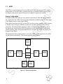
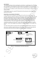
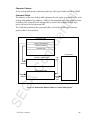
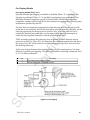
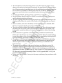
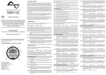
System Configuration
A VRAM (4-Mbit DRAM) and a two-plane frame buffer (2-Mbit DRAM per screen)
are connected to the VDP1. The image data defined in VRAM by the CPU are output
to the display device via the frame buffer.
nfi
de
Draw data is sent from the CPU to the VDP1 via the system control IC and is written
in VRAM. Parts written in VRAM are drawn in the frame buffer in a 16- or 8-bit/
pixel form. The frame buffer data that is drawn is displayed on the display device
via the priority circuit in the VDP2. The priority circuit prioritizes the scroll plane
and the priority plane. The frame buffer has two screens, and draw and display are
changed every frame.
The information that controls draws is set in the VDP1 system registers by the CPU
via the system controller IC. The system registers control draws.
Co
VRAM
(4 Mbit)
VDP1
System
Controller
IC
GA
CPU
System
Registers
SE
Frame
Buffer
(2 Mbit)
2
VDP2
Frame
Buffer
(2 Mbit)
Figure 1.1 System Configuration
Display
Device
nti
al
Functions of the VDP1
The functions of the VDP1 include the drawing of parts (characters and lines), specification of colors, color calculation of Gouraud shading, specification of clipping
coordinates and local coordinates, and control of display by the frame buffer. Parts,
color, and coordinates are controlled by the command table in VRAM, and display of
the frame buffer is controlled by the system registers.
Parts
nfi
de
The following graphics can be drawn as parts.
· Normal sprites
· Scaled sprites (with zooming)
· Distorted sprites (includes rotation)
· Polygons (quadrangles)
· Polylines (quadrangles comprising four lines)
· Lines
Collectively, sprites are referred to as textured parts, and polygons, polylines, and
lines are referred to as non-textured parts.
Color
· The possible numbers of colors for each textured part are 16, 64, 128, 256,
and 32,768.
Special Functions
Coordinate Control
Co
· When RGB codes are used, color calculation of half-luminance, half-transparency, Gouraud shading, and shadowing are possible.
· Mesh (tiling).
· System and user clipping settings are possible.
· Local coordinates can be set during drawing.
Frame Buffer Display Control
SE
GA
· Enlargement, reduction, and rotation of the entire frame buffer screen.
· Specification of the TV display mode.
· Specification of the frame buffer change mode, the change trigger, and the
plot trigger.
· Specification of double interlace.
· Specification of fill area and fill data during erase/write.
· End status of transfer to the frame buffer as help information during program development.
VDP1 User's Manual
3
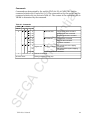
Table 1.1 Classification of Parts
Textured parts
Parts
Part name
Normal
sprites
Scaled
sprites
Polygons
Function
Character, vertical, and
horizontal inversion
Character, vertical, and
horizontal inversion,
enlargement and reduction,
stretching
Character, vertical, and
horizontal inversion,
enlargement and reduction,
stretching, rotation, twisting
Filled quadrangles
Polylines
Lines
Quadrangles
Straight lines
Distorted
sprites
4 vertices and direction of
readout
4 vertices
4 vertices
Starting vertex and ending
vertex
SE
GA
Co
nfi
Nontextured
parts
How defined
1 vertex and direction of
readout
2 vertices and direction of
readout or zoom point, width
and direction of readout
de
Classification
nti
al
Parts
Parts are classified as shown in Table 1.1.
4
nti
al
Textured Parts
Textured parts are called sprites. Sprites draw character patterns. Character patterns
define pixel data as character pattern tables in VRAM. The size of the pixel data is
determined by the color mode and the size of the characters.
Sprites include normal sprites, scaled sprites, and distorted sprites. Normal sprites
can be inverted vertically and horizontally; scaled sprites can be inverted vertically
and horizontally, enlarged and reduced, and stretched; and distorted sprites can be
inverted vertically and horizontally, enlarged and reduced, stretched, rotated, and
twisted.
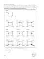
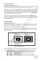
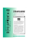
Normal Sprites
nfi
de
The character pattern is drawn at a specified position. The coordinates of the upperleft vertex at which the character pattern is drawn are specified. The character pattern is drawn from the specified coordinates to the right in the X direction and down
in the Y direction. When vertical and horizontal inversion are specified for the readout direction of the character pattern, the right side of the defined character pattern
is drawn from the left and the bottom side is drawn from the top.
Original
graphic
Vertex (A)
Draw
Vertex (A)
Normal
Vertex (A)
A B
Vertical
inversion
B A
Horizontal
inversion
Vertex (A)
Vertical &
horizontal
inversion
... .
Figure 1.2 Normal Sprites
SE
GA
A B
A B
A B
Co
Normal sprites cannot be rotated 90°. Specify the distorted sprite draw command to
perform 90° rotation.
VDP1 User's Manual
5
Scaled Sprites
nti
al
The character pattern is drawn enlarged or reduced at a specified position. There are
two methods by which the position and scaling can be specified. The coordinates of
the upper-left vertex and the lower-right vertex are specified in one method, while
the zoom point coordinates and the horizontal and vertical display widths are specified in another.
Scaled sprites cannot be rotated 90°. Specify the distorted sprite draw command to
perform 90° rotation.
Specification of Coordinates of Two Vertices
nfi
de
In this method, the coordinates of the upper-left and the lower-right vertices are
specified. The draw direction (direction of drawing a character) is determined by the
positional relationship of the lower-right coordinate with respect to the upper-left
coordinate. The character pattern is drawn from the upper-left coordinate toward
the lower-right coordinate. When the value of X of the lower-right coordinate is
smaller than the X value of the upper-left coordinate, the character pattern is inverted horizontally, and when the Y value of the lower-right coordinate is smaller
than the Y value of the upper-left coordinate, the character pattern is inverted vertically.
Co
As with normal sprites, inversion can be specified by the read direction. However,
when the coordinates and the direction of readout are both inverted vertically, the
inversions cancel each other out and the character remains unchanged.
Vertex (A)
A B
Draw
Original
graphic
A B
GA
Normal
Vertex (A)
Vertex (C)
Vertex (C)
Vertex (C)
Vertex (C)
Vertex (A)
Horizontal enlargement,
vertical reduction &
vertical inversion
Vertical-horizontal
reduction & horizontal
inversion
AB
Vertex (A)
Vertical-horizontal
enlargement & verticalhorizontal inversion
SE
Figure 1.3 Scaled Sprites (Two Vertices Specified)
6
... .
Specification of Zoom Point
AB
Display
width
Draw
nfi
AB
Display
width
Normal size
Co
Original
graphic
Zoom
point A B
Zoom
point
Vertical/horizontal reduction
& horizontal inversion with
zoom point at center.
Display
width
Vertical/horizontal enlargement
& vertical/horizontal inverstion
with zoom point at right center.
GA
Horizontal enlargement,
vertical reduction &
vertical inversion with
zoom point at upper right.
Zoom
point
Display
width
AB
Zoom
point
de
nti
al
Scaled sprites can be drawn by specifying the zoom point and display width. The
zoom point of the character pattern, the draw coordinates of the zoom point, and the
display width at which the character pattern is drawn are specified. The zoom point
specifies which point on the character pattern is used as a stationary point for drawing. The point is selected from the left side, center, and right side in the horizontal
direction and from the top side, center, and bottom side in the vertical direction. The
display width specifies the display width in the X direction and the Y direction.
When vertical and horizontal inversions are specified for the character pattern
readout direction, each character patter is drawn inverted vertically and horizontally
with reference to each zoom point. The draw area differs depending on vertical or
horizontal inversion.
SE
Figure 1.4 Scaled Sprites (Zoom Point Specified)
VDP1 User's Manual
7
Distorted Sprites
nti
al
Draw a character pattern by specifying four coordinates. Specify the four draw
coordinates corresponding to the four vertices of the character pattern. These four
coordinates can assume any position relative to each other, and therefore the character pattern can be inverted, enlarged or reduced, rotated, or twisted, depending on
how they are specified.
Distorted sprites are created by skewing the character pattern. At this time holes are
filled to prevent the dropout of pixels. For this reason, there may be some pixels that
are written twice, and therefore the results of half-transparent processing as well as
other processing in color calculation cannot be guaranteed.
SE
GA
Co
nfi
de
Because drawing is done with lines, part of the character pattern may result outside
the graphic formed by linking the four vertices if it is twisted or rotated.
8
Figure 1.5 Distorted Sprites
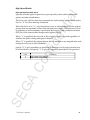
Anti-aliasing
nti
al
Distorted sprites and polygons contain diagonal lines that may result in pixel dropout (aliasing). When this happens, holes are anti-aliased as shown below.
Indicates direction of drawing.
Anti-aliasing
nfi
de
Copied color code
SE
GA
Co
Figure 1.6 Anti-aliasing
VDP1 User's Manual
9
nti
al
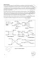
Non-Textured Parts
Non-textured parts are different from textured parts in that they do not require an
original picture, and VRAM is not frequently accessed from the VDP1.
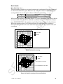
Polygons
Draw a quadrangle by specifying four vertices and filling the enclosed area with a
single color. The four vertices can be specified as desired. The color is specified as a
non-textured color.
de
Polygons contain diagonal lines that may result in pixel dropout (aliasing). When
this occurs, holes are anti-aliased. For this reason, some pixels may be written twice,
and therefore the results of half-transparency processing as well as other color
calculations cannot be guaranteed. Concave polygons can also be drawn. However,
fills may extend outside of the polygon since lines are used to fill the polygon.
Vertex (B)
Vertex (A)
Concave polygon
Co
Vertex (D)
nfi
Vertex (A)
Vertex (C)
Vertex(B)
GA
Vertex (D)
SE
Figure 1.7 Polygons
10
Vertex (C)
Polylines
nti
al
A quadrangle is drawn by connecting four lines. Specify four vertices, and lines
connecting the vertices are drawn in order. Unlike polygons, the area enclosed by
the four vertices cannot be filled. The four vertices can be specified as desired.
Specify the color as non-textured color. Because four lines are drawn, the pixels near
the vertices are written twice. Therefore, the results of half-transparent processing
and other color calculations cannot be guaranteed.
de
Vertex (B)
Vertex (A)
nfi
Vertex (C)
Vertex (D)
Lines
Co
Figure 1.8 Polylines
A line is drawn in a single color between two specified coordinates. Specify the
color as a non-textured color.
Vertex B
Figure 1.9 Line
SE
GA
Vertex A
VDP1 User's Manual
11
nti
al
Color
The functions and special functions related to color are as follows.
• The number of colors per textured part unit is 16, 64, 128, 256, and 32,768.
• In the RGB mode, color calculation of half-luminance, half-transparency,
Gouraud shading, and shadowing is possible.
• Mesh (tiling).
The color bank and RGB code methods are used to express the colors of pixels
drawn (written) in the frame buffer. The color capability of the color bank method is
16, 64, 128, or 256 colors and the RGB code method is 32,768 colors.
de
Color Bank Method
nfi
The color bank method combines the color bank with the palette codes for 16, 64,
128, and 256 colors, and references the colors stored in the color RAM of the VDP2.
A 16 color palette code requires four bits of memory. The upper 12 bits of the color
bank is added to the palette to give a total of 16 bits which is written to the frame
buffer. Graphics that use 64, 128, or 256 colors (8-bit graphics) require a total of eight
bits of memory. Only the lower 6 bits and 7 bits are significant for 64 and 128 color
graphics, respectively, while 256 colors use all 8 bits. The upper 10, 9, and 8 bits of
the color bank are added.
Co
The data written by the color bank method are divided into function bits as shown
in Figure 1.10 and processed in the VDP2. (Refer to the VDP2 manual for more
information.)
MSB
Color bank
LSB
Palette code
GA
Priority
Color calculation
Figure 1.10 Bit Configuration of Color Bank Method
RGB Code Method
SE
The RGB code method represents colors using a 5-bit luminance for each of red,
green, and blue (RGB) dot. The luminance of each of RGB is represented by 00H to
1FH. The closer the number is to 00H, less light is emitted from the RGB dots, the
closer it is to 1FH, more light is emitted. Up to 32,768 colors can be formed by RGB
codes. RGB codes are 16-bit data, and the most significant bit (MSB) is 1.
12
Part Colors
nti
al
The color bank method, the color lookup table method, or the RGB code method can
be used to set the color of sprites. Set a non-textured color for each non-textured part
such as polygons, polylines, and lines.
Color Lookup Table
The color lookup table references the 4-bit graphic data to a 16-color lookup table
and converts it to 16-bit data. Because the 16-bit data in the table are written as is to
the frame buffer, there is no distinction between color bank codes and RGB codes for
textured data.
de
When read to the VDP2, the code is handled as a color bank code when the MSB of
the 16-bit data is “0” and as an RGB code when the MSB is “1.”
Non-textured Color
nfi
Non-textured color is handled as pixel data without the use of a color bank or color
lookup table.
8 Bits/Pixel Color
SE
GA
Co
When using high resolution or specifying a bit width of 8 bits/pixel for a rotated
frame buffer, the graphics will be written to the frame buffer in 8 bits/pixel. When
there are 8 bits/pixel, the lower 8 bits are written to the frame buffer when using a
color lookup table or non-textured color. In either case, the lower 8 bits of the 16 bits
are written to the frame buffer. This will be abbreviated as 8 bits/pixel (high resolution or rotation 8).
VDP1 User's Manual
13
Screen Modes
nti
al
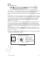
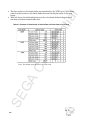
1.2
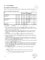
Screen Modes and Display Areas
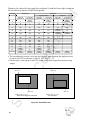
Table 1.2 shows the screen modes and the coordinate values displayed in each.
Table 1.2 Screen Modes and Display Areas
320 H × 224 V
320 H × 240 V
NTSC, PAL
352 H × 224 V
352 H × 240 V
0≤X≤351
0≤X≤351
0≤X≤703
0≤X≤703
0≤Y≤223
0≤Y≤239
Double interlace
NTSC, PAL
320 H × 224 V
320 H × 240 V
0≤X≤319
0≤X≤319
0≤X≤639
0≤X≤639
0≤Y≤447
0≤Y≤479
352 H × 224 V
352 H × 240 V
0≤X≤351
0≤X≤351
0≤X≤703
0≤X≤703
0≤Y≤447
0≤Y≤479
320 H × 240 V
352 H × 240 V
0≤X≤319
0≤X≤351
—
0≤Y≤239
0≤Y≤239
H = Horizontal
V = Vertical
nfi
Non-interlace
31KC, HDTV
de
Non-interlace
Single interlace
X range
Standard
High
resolution
0≤X≤319
0≤X≤639
0≤X≤319
0≤X≤639
Screen mode (pixels)
Y range
0≤Y≤223
0≤Y≤239
SE
GA
Co
• These are coordinate ranges and are not the sizes of the areas occupied in the
frame buffer. For more information about the size of the frame buffer, see “Frame
Buffer” in Section 2.1 Address Map.
• High-resolution display has a color resolution of 8 bits/pixel, which is half the
standard mode. Rotated display of the frame buffer is not possible in highresolution.
• Rotated display of the frame buffer is not possible with double interlace.
• A double interlaced display system uses graphic information from both buffers
to make one frame.
• A single interlaced display system switches frame buffers every two fields and
displays the same picture in both the odd and even display lines. In both cases,
there are no gaps between the scanning lines.
• The resolution in single interlace and non-interlace are the same, and the method
of writing to the frame buffer is the same.
• In 31KC and HDTV, the same color is displayed in 4-pixel units, 2 vertical pixels
and 2 horizontal pixels. That is, the resolution is the same as 320 x 240 (31KC)
and 352 x 240 (HDTV) in the standard mode, and the method of writing to the
frame buffer is the same.
• For information about how to set the interlace, refer to the VDP2 manual.
Notes
Field:
The time it takes the scanning lines to scan one screen (1/60 second).
Frame: The time period during which one image is displayed. If interlaced,
two fields make one frame (1/30 second.)
14
Rotated Reading of Frame Buffer
SE
GA
Co
nfi
de
nti
al
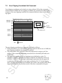
• By reading the frame buffer diagonally, the entire frame buffer plane can be displayed rotated.
• Display coordinates that exceed the frame buffer address range are handled as
transparent (XX00H for 8-bit graphics and 0000H for 16-bit graphics).
• Even if rotated reading of the frame buffer is performed, the clipping area and
erase/write area remain fixed with respect to the frame buffer plane. Therefore,
the clipping area and erase/write area become inclined with respect to the display
screen.
• To prevent dropout of any of the display screen when the frame buffer is displayed rotated, the coordinate range of the frame buffer must be made large. In
this case the frame buffer is set to 8 bits/pixel and the screen to 512 × 512 rather
than 512 × 256. The number of colors that can be expressed at one time becomes
fewer than 256.
• Rotation is prohibited when normal, high resolution, HDTV, or double interlace is
set.
• The read start coordinates and read movement value for rotated reading from the
frame buffer are received from the VDP2.
• Rotated reading of the frame buffer is only valid in rotation 16 and rotation 8, and
is prohibited in all other cases. In the case of non-rotation, any rotation data received from the VDP2 are invalid and the parameters of the VDP1 become valid.
VDP1 User's Manual
15
SE
GA
Co
nfi
de
nti
al
(Page 16 is blank in the original Japanese version.)
16
nti
al
Chapter 2
Co
nfi
de
Address Map
GA
Contents
2.1
SE
2.2
VDP1 User's Manual
Address Map .................................................................................... 18
VRAM ................................................................................. 19
Frame Buffer ....................................................................... 20
System Registers ................................................................ 23
Tables in VRAM ............................................................................... 24
Command Table .................................................................. 25
Color Lookup Table .............................................................26
Gouraud Shading Table ..................................................... 26
Character Pattern Table ..................................................... 26
17
2.1
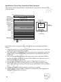
Address Map
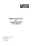
*3
VRAM
(4 Mbit)
080000~0BFFFFH
Frame buffer 0
(2 Mbit)
Reserved
100000~17FFFFH
System
registers
180000~1FFFFH
Access
prohibited
Notes
*2
*3
SE
GA
Figure 2.1 Address Map
18
*2
The following tables are stored in VRAM.
Command tables,
Character pattern tables
Color lookup tables
Gouraud shading tables
The frame buffer comprises two screens at
080000~0BFFFFH. Only the drawing screen can
be accessed. The display screen cannot be accessed.
Address is absolute. To find absolute address,
add 5C00000H.
Co
*1
Frame buffer 1
(2 Mbit)
nfi
0C0000~0FFFFFH
*1
de
000000~07FFFFH
nti
al
Figure 2.1 shows the address map for the VRAM, frame buffer, and system registers
controlled by the VDP1.
VRAM
SE
GA
Co
nfi
de
nti
al
• The VRAM is a 4-Mbit DRAM.
• The command table, sprite character pattern table, color lookup table, and
Gouraud shading table are defined in VRAM. It doesn’t matter where in VRAM
the data of each are, or whether they are in a nested condition. They are referenced by specifying the address of each.
• Fetching of the command must be performed from the top (000000H) of VRAM.
• Fetching of VRAM is repeated in the following order:
Command table
Gouraud shading table (only when Gouraud shading is used)
Color lookup table (only when lookup table method is used)
Character pattern table (only when drawing sprites)
• When fetching of the command table goes beyond the end address (07FFFFH) of
VRAM, fetching wraps to the top address (000000H) of VRAM.
• Byte access and word access are both possible from the CPU.
• Read-write access of the VRAM by the system controller IC, and parameter read
and pattern read access by the VDP1, are performed after assigning an order of
priority.
• The order of priority of access of the VRAM is always: system controller (system
controller IC) > drawing.
• Because access is performed after assigning an order of priority, there may be
more than 10 wait cycles according to that timing, depending on the operating
clock of the CPU. The operating clock of the CPU is 28 MHz.
• Perform access from the CPU when drawing is not being performed in order to
prevent interruption of drawing. To determine if drawing is being performed, poll
the system registers, or use an interrupt signal. Access of the VRAM and frame
buffer is performed in a short period of time using burst transfer.
VDP1 User's Manual
19
Frame Buffer
SE
GA
Co
nfi
de
nti
al
• The frame buffer comprises two 2-Mbit DRAM and is divided into two screens: a
display frame buffer and a draw frame buffer.
• The function of the two buffers is changed immediately before the screen display
period (DISP). After powering on or resetting, frame buffer 0 becomes the drawing frame buffer, and frame buffer 1 becomes the display frame buffer.
• Read-write access of the frame buffer by the system controller IC is performed
only on the draw frame buffer. The display frame buffer becomes the rear bank, so
it cannot be accessed.
• Drawing is performed in sync with the CPU operating clock. The CPU operating
clock is 28 MHz, and the data for 1 pixel is drawn in sync with this.
• Read-write access of the frame buffer by the system controller IC and draw access
by the VDP1 are performed after assigning an order of priority.
• The order of priority of access of the frame buffer is always: system controller IC >
drawing
• When access from the system controller is performed during drawing, drawing is
interrupted and must wait. Therefore this situation should be avoided as much as
possible.
• Because drawing and access of the CPU are not performed together, perform
control by using a method that uses a manual start for drawing start.
• Access can be performed using word access. Byte access is only possible when
display is 8 bits/pixel. Do not use byte access when display is 16 bits/pixel.
• The entire frame buffer can be displayed rotated by reading the frame buffer
diagonally. Also, by skipping or repeating read addresses, the entire frame buffer
plane can be enlarged or reduced. Rotation, enlargement, and reduction can be
performed simultaneously.
• Rotation is specified from the VDP2. Refer to the VDP2 instruction manual for
more information about the specification of rotation.
20
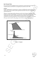
Frame Buffer Plane
SE
GA
Co
nfi
de
nti
al
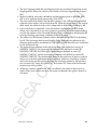
The coordinates of the frame buffer plane are as follows. Coordinates increase in
value toward the lower-right.
X
-1024 ≤ X ≤ 1023
Y
-1024 ≤ Y ≤ 1023
Operation cannot be guaranteed when specified values exceed these values.
Figure 2.2 Frame Buffer Plane
As shown in Figure 2.2, parts can be positioned outside the display screen. However,
nothing is written for parts that exceed the range of the frame buffer plane.
VDP1 User's Manual
21
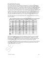
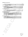
Pixel Data in Frame Buffer
nti
al
The pixel data in the frame is shown below. There is 16-bit and 8-bit data. RGB data,
which does not go through the color RAM in the VDP2, is only 16-bit data. When all
bits are 0, the dot is treated as a transparent dot by the VDP2.
• Bit configuration when data goes through color RAM (color RAM address)
16-color mode b15* b14 b13 b12 b11 b10 b9
(4 bits/pixel)
b8
b7
b6
b5
64-color mode b15* b14 b13 b12 b11 b10 b9
(6 bits/pixel)
b2
b1
b0
Character data
b8
b7
Color bank
b6
b5
b4
b3
b2
b1
b1
b0
Character data
128-color mode b15* b14 b13 b12 b11 b10 b9
(7 bits/pixel)
b8
b7
Color bank
b6
b5
b4
b3
b2
b0
Character data
nfi
256-color mode b15* b14 b13 b12 b11 b10 b9
(8 bits/pixel)
Color bank
b3
de
Color bank
b4
b8
b7
b6
b5
b4
b3
b2
b1
b0
b1
b0
Character data
Co
Note: b15 = 0 when RGB data are mixed; b15 can be either when not mixed.
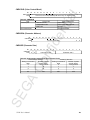
• Bit configuration when data do not go through color RAM (RGB data)
RGB mode
(16 bits/pixel)
1
b14 b13 b12 b11 b10
BLUE data
b9
b8
b7
b6
b5
b4
GREEN data
b3
b2
RED data
GA
• Bit configuration when pixel data is 8 bit (color RAM address)
16-color mode
(4 bits/pixel)
64-color mode
(6 bits/pixel)
SE
128-color mode
(7 bits/pixel)
256-color mode
(8 bits/pixel)
22
b7
b6
b5
b4
Color bank
b7
b6
b5
Color bank
b7
b6
Color bank
b7
b6
b4
b3
b2
b1
b0
Character data
b3
b2
b1
b0
Character data
b5
b4
b3
b2
b1
b0
Character data
b5
b4
b3
b2
b1
Character data
b0
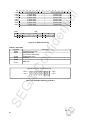
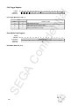
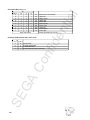
System Registers
Table 2.1 System Registers
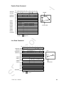
Description
TV mode selection
Frame buffer change mode
Draw trigger
Erase/write data
Erase/write upper-left coordinate
Erase/write lower-right coordinate
Draw forced termination
Transfer end status
Last operation command address
Current operation command address
Mode status
Co
Name
TVHR
FBCR
PTMR
EWDR
EWLR
EWRR
ENDR
EDSR
LOPR
COPR
MODR
Access
Write-only (word)
Write-only (word)
Write-only (word)
Write-only (word)
Write-only (word)
Write-only (word)
Write-only (word)
Read-only (word)
Read-only (word)
Read-only (word)
Read-only (word)
SE
GA
Address
100000H
100002H
100004H
100006H
100008H
10000AH
10000CH
100010H
100012H
100014H
100016H
nfi
de
nti
al
• System registers are memory used for making system settings for the VDP1. They
are housed inside the VDP1 separately from the VRAM and frame buffer.
• There are read-only registers and write-only registers.
• The write-only registers are used to control display of the frame buffer. They
select the TV mode, specify change of display and the drawing trigger, and define
the fill data and area for erase/write. Drawing can also be forcibly terminated.
• Read-only registers are used as help information during program development.
They make it possible to know the address of the command table that underwent
draw processing last.
• Read/write access from the CPU must be performed in word units.
• Do not use DMA burst transfer when accessing the system registers.
• Except for the plot trigger register (PTMR), the values in the write-only registers
become undefined after powering on and after resetting, so be sure to set the
values from the CPU. Undefined data is displayed from the frame buffer until a
suitable value is set.
• Set the unused bits of write-only system registers to “0”.
VDP1 User's Manual
23
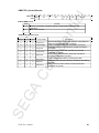
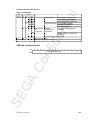
2.2
Tables in VRAM
nti
al
The command table, color lookup table, Gouraud shading table, and character
pattern table are defined in VRAM. Table 2.2 shows the sizes and boundaries of the
tables.
Table 2.2 Tables in VRAM
Name
Function
Commands
Size
Boundary
Normal sprite draw command
Scaled sprite draw command
Draw
Distorted sprite draw command
Commands
Polygon draw command
Non-textures
Polyline draw command
Command
1EH
20H
Line draw command
Table
User clipping coordinate set
Coordinate Clipping coordinate command
set commands System clipping coordinate set
Set
command
Commands
Local coordinate set command
Drawing end command
Color lookup table
20H
20H
Gouraud shading table
8H
8H
Character pattern table
optional*
20H
Note: *Differs depending on the character size and color mode.
nfi
de
Textured
Draw
Command
SE
GA
Co
The VRAM is 4 Mbit (512 Kbyte), and it is addressed in byte units from 000000H to
07FFFFH. Table data cannot be written beyond 07FFFFH. Each table must be kept
within the size of the VRAM.
24
Command Table
nti
al
• The command table is a table in VRAM where commands are defined, and in
which the VDP1 reads commands, draws parts and processes clipping.
• The commands are as follows:
Draw commands
These are divided into texture drawing and non-texture drawing. Texture
drawing includes normal sprite, scaled sprite, and distorted sprite draw
commands. Non-texture drawing includes polygon, polyline, and line
draw commands. Draw commands draw these parts.
Clipping coordinate set commands
Local coordinate set commands
de
Includes user clipping and system clipping coordinate set commands, and
they set the draw area for parts.
Specifies the definition of the parts draw coordinate by the local coordinate.
Draw end command
nfi
Terminates drawing.
SE
GA
Co
• The size of the command table is 1EH (30) bytes, and its boundary is 20H (32)
bytes.
• Each command is read to the VDP1 and is processed. This operation is referred to
as fetching.
• Fetching of the command table is performed from the top address (000000H) of
VRAM, and the next command table is fetched according to the specification of
the jump mode.
• According to the command table specification, the color lookup table, Gouraud
shading table, and character pattern table are referenced after the command table.
VDP1 User's Manual
25
Color Lookup Table
nti
al
• This is a table in which 16-bit color codes for 16 colors are defined in VRAM.
• When a lookup table method is used for the color mode according to the texture
draw command, the table is referenced as color data.
• The pixel data of character patterns is converted to color codes and written to the
frame buffer.
• The size of the table is 20H (32) bytes, and its boundary is also 20H (32 ) bytes.
• The table is referenced according to the instruction at the lookup table address of
the texture draw command.
Gouraud Shading Table
Character Pattern Table
Co
nfi
de
• This is a table in VRAM in which 16-bit RGB codes for 4 points are defined.
• It is referenced when the processing of Gouraud shading by color calculation is
instructed by the draw command for the part.
• The pixel data of the part undergoes processing for Gouraud shading and is
written to the frame buffer.
• The size of the table is 8H bytes, and its boundary is also 8H bytes.
• It is referenced according to the instruction at the Gouraud shading table address
of the draw command for the part.
• When Gouraud shading is performed, the pixel data of the part is limited to RGB
code. When the pixel data of the part is a color bank code, the results cannot be
guaranteed.
SE
GA
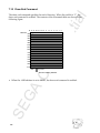
• This is a table in VRAM in which the pixel data for character patterns is defined.
• The table is referenced by the texture draw command.
• The pixel data is defined as 4, 8, or 16 bits/pixel, according to the specification of
the color mode.
• In the color bank mode, a color bank is added to the pixel data of the character
pattern; in the color lookup table mode it is converted in the color lookup table; in
the RGB mode it is written, as is, to the frame buffer.
• The size of the table is determined by the size of the characters and the color
mode. Its boundary is 20H (32) Bytes.
• The table is referenced according to the instruction at the character address of the
texture draw command.
26
nti
al
Chapter 3
SE
GA
Co
nfi
de
Processing Flow
VDP1 User's Manual
Contents
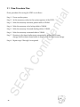
3.1 Draw Procedure Flow ................................................. 28
3.2 Command Table Flow ................................................. 30
3.3 Table Referencing ....................................................... 31
27
Draw procedure flow using the VDP1 is as follows.
Step 1. Power on the system.
nti
al
3.1 Draw Procedure Flow
Step 2. Set the necessary values in the system registers of the VDP1.
Step 3. Write the necessary character pattern table to VRAM.
Step 4. Write the necessary color lookup table to VRAM.
de
Step 5. Write the necessary Gouraud shading table to VRAM.
Step 6. Write the necessary command table to VRAM.
Step 7. Drawing to the frame buffer starts automatically at the start of frame
change, and the drawn frame buffer is displayed in the next frame change.
SE
GA
Co
nfi
Step 8. Repeat steps 3 through 6 as required.
28
Table Access
nti
al
The procedure VDP1 uses to access the table in VRAM and draw is as follows:
Step 1. Controls drawing and display according to the instructions set in the system
registers.
Step 2. Fetches the command table at the top address of VRAM.
Step 3. The fetched command table:
(2)
(3)
Terminates drawing in the case of a draw end command (goes to step
9).
Is ignored when jump mode is skipped; reading of the table is terminated and the table is not processed (goes to step 8).
In cases other than (1) and (2), goes to step (4).
de
(1)
Step 4. In the case of a clipping coordinate set command or a local coordinate set
command, each is processed (goes to step 8).
nfi
Step 5. In the case of a drawing command, the Gouraud shading table and color
lookup table are read if specified.
Co
Step 6. In the case of a textured drawing, the character pattern table is read and is
written to the frame buffer according to the specification. At this time,
processing of the color mode, color calculation, inversion, enlargement and
reduction, and rotation are performed.
Step 7. In the case of a non-textured drawing, writing to the frame buffer is performed according to the specification.
Step 8. The next command table is fetched according to the specification of the
jump mode and processing of the command table is repeated (goes to step
3).
SE
GA
Step 9. Drawing is repeated with the start of framing (goes to step 1).
VDP1 User's Manual
29
3.2 Command Table Flow
·
·
·
·
Jump to a command table
Skip to a command table
Call a command table group (subroutine)
Return (to main routine)
nti
al
Except for the draw end command, a jump mode to the next command table to be
processed can be specified in other commands. Those jump modes include the
following.
000000 H
VRAM/Command Table
Clipping coordinates
Local coordinates
Parts
Subroutine call
nfi
Parts
Jump
• Moves to specified table.
:
Parts
Parts
Return
• Returns to main routine.
Co
Parts
• Fetched from the top of VRAM
during frame switching.
• The specified table receives
a subroutine call.
Parts
:
de
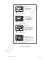
Figure 3.1 shows an example of the flow of a command using a jump mode.
Parts
Skip/parts
Parts
Parts
Jump
• Skips (this part is not drawn).
Parts
GA
Parts
Jump
:
Clipping coordinate change
Parts
Local coordinate change
Parts
SE
:
Terminate drawing
30
:
• Drawing is terminated.
Figure 3.1 Command Table Flow
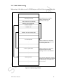
3.3 Table Referencing
VRAM
:
:
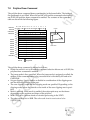
Parts draw command
:
Color mode and color calculation
Character address
Character size
:
:
• The data size of the command
table is 1EH bytes and the
boundary is 20H bytes.
de
Address of color lookup table
nti
al
Referencing of the tables stored in VRAM begins with the following command table.
nfi
Address of Gouraud shading table
:
:
:
Co
Color lookup table
:
:
• Both the data size and boundaries
are 20H bytes when the color mode
is the lookup table mode.
:
:
Gouraud shading table
:
SE
GA
:
VDP1 User's Manual
• Both the data size and boundaries
are 8H bytes when Gouraud
shading is used for color calculation.
:
:
Character pattern
:
:
• In the case of a sprite draw command,
the data size has 20H-byte boundaries
as determined by the character size
and color mode.
:
:
Figure 3.2 Referencing of Tables
31
SE
GA
Co
nfi
de
nti
al
(This page is blank in the original Japanese document.)
32
nti
al
Chapter 4
Co
nfi
de
System Registers
Contents
4.1
TV Mode Selection Register ............................................................ 36
Frame Buffer Change Mode Register ............................................. 38
4.3
Plot Trigger Register ........................................................................ 45
4.4
Erase/Write ...................................................................................... 46
SE
GA
4.2
Erase/Write Data Register ................................................. 46
Erase/Write Upper-Left Coordinate Register ...................... 47
Erase/Write Upper-Right Coordinate Register ................... 47
4.5
Draw Forced Termination Register ................................................. 51
4.6
Transfer End Status Register .......................................................... 52
4.7
Last Operation Command Address Register .................................. 54
4.8
Current Operation Command Address Register ............................. 55
4.9
Mode Status Register ...................................................................... 57
VDP1 User's Manual
33
Table 4.1 System Registers
Function
Specifies TV display mode
100002H
Access
Write-only
(word)
Write-only
(word)
Write-only
(word)
Controls start of drawing
100004H
100008H
Write-only
(word)
Write-only
(word)
10000AH
Write-only
(word)
Specifies fill data for frame buffer
during erase/write
Specifies upper-left coordinate of area
in frame buffer to fill during
erase/write
Specifies lower-right coordinate of
area in frame buffer to fill during
erase/write
Forces termination of drawing
FBCR
PTMR
Plot trigger
Erase/write data
EWDR
100006H
Erase/write upper left coordinate
EWLR
Erase/write lower right coordinate
EWRR
Plot abnormal end
ENDR
Transfer end status
EDSR
Last Operation
Command Address
Current Operation
Command Address
Mode status
LOPR
10000CH
100010H
100012H
COPR
100014H
100016H
GA
SE
34
PTM as occasion
demands
VBE is field
FCM and FMT are set
for each field, others
are frame buffer SW
timing
01B write as the
occasion demands,
00B and 10B write are
frame buffer SW
timing
Frame buffer SW
timing
Frame buffer SW
timing
Frame buffer SW
timing
As the occasion
demands
Status of ‘END’ bit of current/previous
–
frame
Address of last accessed command
–
table for previous frame
Address of last accessed command
–
table being processed
Displays setting of write-only register
–
Co
MODR
Write-only
(word)
Read-only
(word)
Read-only
(word)
Read-only
(word)
Read-only
(word)
Controls frame buffer toggle and
double interlace mode
Internal update
period
de
Frame buffer switch
mode
Abbrevi ation
Address
TVMR 100000H
nfi
Register Names
TV mode selection
nti
al
The following table shows the functions of the systems registers.
• Settings that change immediately
nti
al
System Register Settings Switch Timing
The timing with which the system register settings become valid is as follows.
Plot trigger mode (PTM, when 01B is written)
TV mode selection (TVM)
• Settings that change with each field (1/60 second)
de
Frame buffer change mode (FCM)
Frame buffer change trigger (FCT)
• Settings that change with the switching of the frame buffer
nfi
Plot trigger mode (PTM, when 00B or 10B is written)
Even/odd coordinate selection bit (EOS)
Double-density interlace enable (DIE)
Double-density interlace draw line (DIL)
Erase/write data
Erase/write coordinates (upper-left, lower-right)
• Changes following the termination of display of one line after the V-blank IN
interrupt.
SE
GA
Co
Enables V-blank erase/write (VBE)
VDP1 User's Manual
35
4.1
TV Mode Selection Register
TVMR bit 15
100000H
0
Write-only
14
0
13
0
12
0
11
0
10
0
9
8
0
7
0
6
0
5
0
4
0
3
0
2
VBE
1
0
TVM
de
V-Blank Erase/Write Enable (VBE): bit 3
nti
al
The TV mode selection register (TVMR, TV mode register) enables V-blank erase
and specifies the TV display mode. It is a 16-bit write-only register, and is at address
100000H. Its value becomes undefined after powering on or resetting; therefore the
TV display mode must be set. The unused bits must be set to “0.”
nfi
• When VBE = 1, erase/write is performed during V-blank. VBE = 1 can only be set
when FCM = 1 and FCT = 1 are written. For more information, refer to section 4.2,
“Frame Buffer Change Mode Register.”
• When VBE is set to “0” or “1,” TVM of the same value before making the setting
must be set at the same time.
• The VBE setting must be set immediately after the V-blank IN interrupt. Access is
prohibited from the first H-blank IN interrupt after the V-blank IN interrupt until
the next H-blank IN interrupt.
TV Mode Select (TVM): bits 2~0
SE
GA
Co
• Specifies the TV display mode.
• For more information about the coordinate values of the displayed area, refer to
“Screen Mode and Display Areas” in section 1.2.
• When TVM = 010B(2), the frame buffer has only 512 (H) x 256 (V) pixels, and
therefore if the screen is greatly inclined, a transparent area occurs in the display
screen.
• Since only non-interlace is possible when HDTV is specified (TVM = 100B(4)), and
only non-interlace and single interlace are possible when rotated display is specified (TVM = 010B(2), 011B(3)), the frame buffer change mode register must be set
to double-interlace disable (DIE bit = 0). For more information, refer to section 4.2,
“Frame Buffer Change Mode Register.”
• TVM settings must be performed from the second H-blank IN interrupt after the
V-blank IN interrupt to the H-blank IN interrupt immediately after the V-blank
OUT interrupt.
36
1
0
0
0
0
0
0
1
0
1
0
0
1
1
1
0
0
Interlace
Yes
Yes
Single
Only
Single
Only
No
VDP CLK (MHz)
NTSC
26.8426
26.8426
28.6364
28.6364
26.8426
26.8426
28.6364
28.6364
26.8426
26.8426
28.6364
28.6364
26.8426
26.8426
28.6364
28.6364
26.8426
28.6364
PAL
26.6564
26.6564
28.4375
28.4375
26.6564
26.6564
28.4375
28.4375
26.6564
26.6564
28.4375
28.4375
26.6564
26.6564
28.4375
28.4375
26.6564
28.4375
SE
GA
All other
nfi
Bits
2
Frame
Screen Mode
buffer
Resolution
Bit width
screen
Name
HxV
(bit/pixel)
size
Normal
320x224
512 H
(NTSC, PAL)
320x240
16
x
352x224
256 V
352x240
High
640x224
1024 H
resolution
640x240
8
x
(NTSC, PAL, Hi704x224
256 V
Res)
704x240
Rotation 16
320x224
512 H
(NTSC, PAL
320x240
16
x
Rotation)
352x224
256 V
352x240
Rotation 8 (NTSC,
320x224
512 H
PAL
320x240
8
x
Rotation)
352x224
512 V
352x240
HDTV
320x240
16
512 H x
(31KC, HDTV)
352x240
256 V
Setting prohibited (do not use)
Co
TVM
de
Table 4.2 Screen Modes
nti
al
• The function of each bit is as follows.
Bit 2: HDTV enable bit
0 = NTSC, PAL
1 = HDTV, 31KC
Bit 1: Frame buffer rotation enable bit
0 = non-rotation
1 = rotation
Bit 0: Bit depth selection bit
0 = 16 bits/pixel
1 = 8 bits/ pixel
VDP1 User's Manual
37
4.2
Frame Buffer Change Mode Register
FBCR
100002H
Write-only
bit
15
0
14
0
13
0
12
0
11
0
10
0
9
0
8
0
6
0
5
0
4
EOS
3
2
1
0
DIE
DIL
FCM
FCT
de
Frame Buffer Change Mode (FCM): bit 1
Frame Buffer Change Trigger (FCT): bit 0
7
0
nti
al
The frame buffer change mode register (FBCR, frame buffer change register) controls
drawing and display change of the frame buffer, as well as double interlace drawing.
It is a 16-bit read-only register at address 100002H. Its value becomes undefined
after powering on or resetting, and therefore the change mode must be set. Unused
bits must be set to “0.”
Co
nfi
• Normally the two frame buffers are used as a front screen and a back screen. The
front screen is displayed and the back screen is drawn. Also, the front screen and
back screen are toggled after the time required to change one frame has elapsed.
The front screen that was displayed becomes the back screen to be drawn, and the
back screen that was being drawn becomes the front screen to be displayed.
• Only that part of the frame buffer being drawn can be accessed. The side being
displayed cannot be accessed.
• The number of characters that can be drawn in one frame is limited. Therefore, in
order to draw multiple characters, the manual mode must be set and controls
erased and changed from the CPU.
• When selected data is written from the CPU to FBCR, the values of FCM and FCT
are updated at the time of a field change in the VDP1.
• When in the manual mode, the FCT bit setting is only valid for the next frame.
The contents of FCT are updated internally at the time of frame change.
• Make the FCM and FCT settings immediately after the V-blank OUT interrupt.
Access is prohibited from the first H-blank IN interrupt after the V-blank OUT
interrupt until the next H-blank IN interrupt.
FCT
0
1
0
1
0
1
0
1
38
Change mode
1-cycle mode
Setting prohibited
Manual mode (erase)
Manual mode (change)
Setting prohibited
Setting prohibited
Setting prohibited
Manual mode (erase and
change)
GA
FCM
0
0
1
1
0
0
1
1
SE
VBE
0
0
0
0
1
1
1
1
Change time
Change every 1/60 second
—
Erase in next field
Change in next field
—
—
—
Erase by V-blank and change
in next field
nti
al
1-Cycle Mode
• This is the normal mode.
• One frame changes automatically every 1/60 second.
• Set the value of the VBE and FCT bits to “0.”
nfi
de
Erase (Manual Mode)
• Erase/write for one frame is controlled from the CPU.
• Manual erase/write of the frame buffer is specified by writing “0” to the VBE,
FCM and FCT registers. Erase/write of the display frame buffer is performed in
the next specified field, and the display frame buffer is cleared.
• Changing of the drawing and display frame buffers is not performed. Because the
display frame buffer is cleared when erase is performed, it is necessary to specify
change in the next field when display is performed for which erase is specified
and to perform change of drawing and display.
• This mode is used when there are two or more fields in one frame, as in double
interlace. Also, when changing from manual mode to the 1-cycle mode, this erase
is used in the field before changing.
• Erase is used when it is known that frame change will be performed two fields in
advance. Use erase and change when it is unclear up until the prior field that
frame change will be performed.
SE
GA
Co
Change (Manual Mode)
• The changing of one frame is controlled by the CPU.
• Change is specified by writing “0” to the VBE register and “1” to the FCM and
FCT registers. The drawing and display are changed in the next specified field.
• Because erase/write is not performed, it is necessary to specify erase in the prior
field in which change is specified and to erase/write the frame buffer.
• Until change is specified, characters can be drawn in the back screen.
• This change is normally used when switching from the 1-cycle mode to the
manual mode. This change is also used when changing the frame buffer in
manual mode.
VDP1 User's Manual
39
de
nti
al
Erase & Change (Manual Mode)
• By writing “1” to the VBE register, V-blank erase is specified; and by writing “1”
to the FCM and FCT registers at the same time, switching of the frame buffer after
V-blank is specified.
• This mode is used when frame change is unclear up until the prior V-blank, as
when the frame buffer cannot be changed by the end of processing by the CPU.
• Once VBE has been set to “1,” erase/write is performed automatically even in the
next V-blank, and therefore VBE must be set to “0” before the next V-blank after
frame change.
• Place the erase & change setting immediately after the V-blank IN interrupt. When
set at another time, the change may be performed without being able to erase.
• If the timing for frame change is known in advance as in normal, high resolution,
and interlace, specify erase & change and perform erase/write during the display
period. In this case, erase/write of the entire display screen is possible.
SE
GA
Co
nfi
Sequence When Using Erase & Change
1) Set VBE to “0” and FCM and FCT to “1.”
2) Wait for the end of processing by the CPU without selecting the TV mode or
setting the FB change mode.
3) When processing by the CPU ends by the H-blank IN interrupt time (224th line
in 224-line display and 240th line in 240-line display) immediately before Vblank, then VBE, FCM, and FCT are set to “1” (erase & change). The erase &
change setting should be placed immediately after the V-blank IN interrupt.
4) V-blank erase is started after completion of the V-blank IN interrupt.
5) At the end of V-blank, erase/write is interrupted and the frame is changed.
6) If erase/write is not completed, erase/write non-erased areas with polygons.
7) Return VBE to “0” after the V-blank OUT interrupt to stop V-blank erase.
8) Return to 2).
40
Example
nti
al
Table 4.3(a) shows the frame buffer change mode being used.
Table 4.3(a) Example of Use of Frame Buffer Change Mode (Fixed at VBE = 0)
Display and
erase/write
Draw
1
Display
1
1
1
0
0
1
0
0
Display and
erase/write
Draw
Display
Display and
erase/write
Draw
Draw
Draw
Draw
Draw
Display
Display and
erase/write
Draw
Display
Change
time
60 frames/sec
Manual mode
(change)3
20 frames/sec
Manual mode (erase)4
Manual mode
(change)4
Manual mode (erase)5
1-cycle mode
60 frames/sec
Display and
erase/write
Co
Display and
erase/write
Draw
1Value written to register immediately after the V-blank OUT interrupt.
2Changes from the first of the field.
3Changes from the 1-cycle mode to the manual mode with change.
4Be sure to continue to specify erase & change.
5Specify erase in the field immediately before changing to the 1-cycle mode.
SE
GA
Notes:
Display and
Erase/write
Draw
Frame buffer
change mode
1-cycle mode
nfi
1
Display and
erase/write
Draw
Frame
buffer 1 2
Display and
erase/write
Draw
de
Setting1
Frame
FCM FCT
buffer 0 2
0
0
Draw
VDP1 User's Manual
41
SE
GA
Co
nfi
de
nti
al
Table 4.3 (b) Example of Use of Frame Buffer Change Mode (VBE Is Used)
42
Double Interlace Enable (DIE): bit 3
Double Interlace Draw Line (DIL): bit 2
DIL
0
1
0
1
Interlace mode
Non-interlace/single interlace
Setting prohibited
Double interlace
Double interlace
Co
Single interlace mode display
line 0
Plot after next frame change
Plot both even and odd lines
—
Plot even-numbered lines only
Plot odd-numbered lines only
nfi
DIE
0
0
1
1
de
nti
al
• In single interlace, the same picture is displayed in the even fields and the odd
fields. In double interlace, however, the vertical resolution is doubled by displaying different pictures (each draws only even lines and odd lines, respectively) in
the even fields and the odd fields.
• Double interlace is enabled by DIE = 1.
• The contents of the first screen displayed after changing DIE cannot be guaranteed.
• In double interlace, the fields are changed every 1/60 second, and therefore
FCM = FCT = 0 (1-cycle mode) is set.
Double interlace mode display
line 0
line 0
line 1
line 1
line 2
line 1
line 2
line 3
line 4
GA
line 2
line 3
line 3
SE
• Appears as 256 lines vertically
• The frame is changed every 1/60th of a
second, and either the same picture is
displayed two times or the frame is changed
every 1/30th of a second (a 1/60 sec signal is
used and is specified from the CPU).
VDP1 User's Manual
line 5
line 6
line 7
• Appears as 512 lines vertically
• Even and odd numbered lines are
rendered into different frame buffers.
Figure 4.1 Single Interlace and Double Interlace Display
43
Even/Odd Coordinate Select Bit (EOS): bit 4
de
Even/odd coordinate select bit
Samples only pixels at even coordinates
Samples only pixels at odd coordinates
SE
GA
Co
nfi
EOS
0
1
nti
al
• When “1” is specified for high speed shrink (HSS) with a scaled or distorted
sprite, this bit is enabled. When HSS = 1 is specified, lines drawn with a magnification ratio of less than 1 are drawn by sampling only the even or odd pixels of
the original picture data. This bit specifies whether even or odd coordinates are
sampled.
• When EOS = 0, only pixels at even coordinates are sampled. When EOS = 1, only
pixels at odd coordinates are sampled.
• If HSS = 0, this bit is not referenced.
• Refer to “High Speed Shrink” under “6.3 CMDPMOD (Draw Mode Word” for
more information.
44
4.3
Plot Trigger Register
PTMR
100004H
Write-only
bit 15
0
14
0
13
0
12
0
11
0
10
0
9
0
Plot Trigger Mode (PTM): bits 1, 0
8
0
nti
al
The plot trigger mode register (PTMR) controls the start of drawing. It is a 16-bit
write-only register at address 100004H. Its value is reset to 00B after powering on or
resetting. Set unused bits to “0”.
7
0
6
0
5
0
4
0
3
0
2
0
1
0
PTM
PTM
Drawing mode
0
0
1
0
1
Idle at frame change
Starts drawing when 01B is written
Starts drawing automatically with frame change
Setting prohibited (do not set)
Co
Bit 1
0
0
1
1
nfi
de
• Controls the start of drawing.
• When the plot trigger mode bits are 10B, drawing begins automatically at the start
of the frame.
• When the plot trigger mode bits are made 01B, drawing begins when the register
is written. When 01B is written to the plot trigger mode bits during drawing,
drawing begins from the top of the command table.
• When the plot trigger mode bits are 00B, drawing does not start even at the start
of the frame. An idling condition is set.
• The value of the bits is reset to 00B after powering on or resetting.
GA
• When the plot trigger mode bits are rewritten from 01B to 00B, drawing becomes
valid from the next frame. However, when the plot trigger bits are rewritten from
00B or 10B to 01B, drawing becomes valid at that point and drawing is started
even if drawing is automatically started by 10B.
• When the table is not rewritten the same drawing is performed, and therefore the
results of color calculation of half-transparency change. Use the following procedure to change only the draw start mode without drawing.
Change the plot trigger mode bits from 10B to 00B.
Change the plot trigger mode bits from 00B to 01B in the next frame.
SE
1)
2)
VDP1 User's Manual
45
4.4
Erase/Write
nti
al
Before rendering data into the frame buffer, the VDP1 erases the contents of the
frame buffer. This erasure is referred to as erase/write, and it specifies the fill area to
be erased and the fill data to be written to that area. The three registers related to
erase/write are the erase/write data register, the erase/write left coordinate register
and the erase/write right coordinate register.
EWDR
100006H
16 bits/pixel
8 bits/pixel
Write-only
bit 15
14
13
12
11
8
7
6
5
4
3
2
1
0
Erase/write data
Erase/write data for even X coordinates
Erase/write data for odd X coordinates
9
nfi
Erase/Write Data: bits 15~0
10
de
Erase/Write Data Register
The erase/write data register (EWDR) specifies the fill data during erase/write. It is
a 16-bit write-only register at address 100006H. Its value becomes undefined after
powering on or resetting, and therefore the fill data must be set.
SE
GA
Co
When parts are written to the frame buffer, the VDP1 automatically erases the frame
buffer. At the time of this erase/write, the frame buffer is filled with the 16-bit data
set in the erase/write register. Erase/write is performed 2 pixels at a time when the
frame buffer depth is 8 bits/pixel. The area of erase/write is set by the erase/write
left coordinate register and the erase/write right coordinate register.
46
EWLR
100008H
Write-only
bit
15
0
14 13 12 11 10 9
Upper-left coordinate X1
8
7
6
5
4
3
2
Upper-left coordinate Y1
1
0
de
Erase/Write Upper-Left Coordinate X1: bits 14~9
Erase/Write Upper-Left Coordinate Y1: bits 8~0
nti
al
Erase/Write Upper-Left Coordinate Register
The erase/write left register (EWLR) sets the upper-left coordinate of the erase/
write area. It is a 16-bit write-only register at address 100008H. Its value becomes
undefined after powering on or resetting, and therefore the coordinates must be set.
Set unused bits to “0.”
EWRR
10000AH
Write-only
bit 15
nfi
Erase/Write Upper-Right Coordinate Register
The erase/write right coordinate register (EWRR) sets the lower-right coordinate of
the erase/write area. It is a 16-bit write-only register at address 10000AH. Its value
becomes undefined after powering on or resetting, and therefore the coordinates
must be set. Set unused bits to “0”.
14 13 12 11 10 9
Lower-right coordinate X3
8
7
6
5
4
3
2
Lower-right coordinate Y3
1
0
Erase/Write Lower-Right Coordinate X3: bits 15~9
Erase/Write Lower-Right Coordinate Y3: bits 8~0
SE
GA
Co
• These registers specify the fill area in the frame buffer during erase/write.
• The X coordinate is set in 8-pixel units when there are 16 bits/pixel (normal,
rotation 16, HDTV) and in 16-pixel units when there are 8 bits/pixel (high resolution, rotation 8). When the value of the system register is 1, it becomes 8 or 16.
The actual lower-right X coordinate takes a value that is 8 or 16 times the register
setting and from which 1 is subtracted.
• The Y coordinate is set in one-line units. Because the register setting for the Y
coordinate is doubled during double interlace, the actual coordinate value should
be set to one half. For example, when the setting is 223, the coordinate becomes
447.
• The actual X coordinate is expressed by the following equations.
16 bits/pixel
Upper-left coordinate X 1 = register setting × 8
Lower-right coordinate X 3 = register setting × 8 – 1
8 bits/pixel
Upper-left coordinate X1 = register setting × 16
Lower-right coordinate X3 = register setting × 16 – 1
VDP1 User's Manual
47
16 bits/pixel
0
1
2
:
31
0
8
16
:
248
Lower right
coordinate X3
Setting
prohibited
7
15
:
247
32
256
255
33
:
40
:
43
44
:
62
63
264
:
320
:
344
352
:
496
504
Setting
prohibited
Setting
prohibited
263
:
319
:
343
351
:
495
503
64
over 65
de
Upper left
coordinate X1
8 bits/pixel
High Resolution
Rotated 8
Upper left
Lower right
Upper left
Lower right
coordinate X1 coordinate X3 coordinate X1 coordinate X3
Setting
Setting
0
prohibited
0
prohibited
16
15
16
15
32
31
32
31
:
:
:
:
496
495
496
495
Setting
512
511
prohibited
511
Setting
Setting
528
527
prohibited
prohibited
:
:
:
:
640
639
:
:
:
:
:
:
688
687
:
:
704
703
:
:
:
:
:
:
992
991
:
:
1008
1007
:
:
Setting
prohibited
1023
:
:
Setting
Setting
Setting
Setting
prohibited
prohibited
prohibited
prohibited
511
Setting
prohibited
nfi
Value set
in register
nti
al
Therefore the values that the upper-left coordinate X1 and the lower-right coordinate
X3 can take are as shown in the following table.
GA
(X1, Y1)
Co
• The coordinates for erase/write are not checked, and therefore the registers must
be set in the CPU in advance so that X1 < X3 and Y1 ≤ Y3.
• Set the erase/write range in each TV mode within their respective memory map
ranges.
(X3, Y3)
(X3, Y3)
SE
(a) X1 < X3, Y1 ≤ Y3
White area undergoes erase-write
48
(X1, Y1)
(b) X1 ≥ X3, Y1 > Y3
No erase-write
Figure 4.2 Erase/Write Area
nfi
de
nti
al
• If the setting is X1 ≥ X3 or Y1 > Y3, then erase/write is performed for 1 dot in the
normal or high-resolution mode and for 8 dots in the case of rotation or HDTV. In
these cases, erase/write is performed under the assumption that the area (X1, Y1)
is set to (X3 = X1 + 1, Y3 = Y1).
• When VBE = 0 in the normal or high-resolution mode, erase/write is performed
beyond the frame buffer during the display period. When setting the X3 coordinate beyond the display screen, after the end of the effective data (fall of HTIM),
erase/write is continued for 4 pixels in the normal mode and for 8 pixels in the
high-resolution mode, and erase/write is not performed beyond the display
screen other than in those areas.
• When the erase/write area is set within the display screen area, no erase/write is
performed outside the display area.
• Erase/write is not affected by clipping.
• Erase/write cannot be performed on the frame buffer during display when in the
HDTV mode, when the frame buffer is enlarged or reduced, or when display is
rotated. Because erase/write is performed in the vertical blanking period (VBLANK), there is not enough time to erase/write the entire screen. To perform
erase/write on the entire screen, the non-erased areas must be filled with polygons at the start of drawing.
• The number of pixels required for V-blank erase is expressed by
(X3 – X1 + 1) x (Y3 – Y1 + 1) x 8
Co
If this is within the number of pixels that can be used in V-blank erase, then erase/
write is completed.
• The number of pixels that can be used in V-blank erase is given by
{(number of pixels in 1 raster) – 200}
× {(number of rasters in 1 field) – (number of display rasters)}
The respective values are shown in Tables 4.4 and 4.5.
Table 4.4 Number of Rasters and Number of Pixels
Screen mode
Number of pixels in
1 raster
1708
1820
852
848
Number of rasters in
1 field
263
313
525
562
SE
GA
NTSC
PAL
31KC
HDTV
Number of horizontal
pixels
320
352
—
—
VDP1 User's Manual
49
Screen mode
NTSC
PAL
Number of pixels that can
be used
58812
34684
63180
37260
134212
110084
85956
144180
118260
92340
29340
53136
SE
GA
Co
nfi
de
31KC
HDTV
Resolution
(horizontal x vertical)
320 × 224
320 × 240
352 × 224
352 × 240
320 × 224
320 × 240
320 × 256
352 × 224
352 × 240
352 × 256
320 × 480
352 × 480
nti
al
Table 4.5 Number of Pixels that Can Be Used in V-Blank Erase (in Non-Interlace Display)
50
4.5
Draw Forced Termination Register
ENDR
10000CH
Write-only
bit 15
0
14
0
13
0
12
0
11
0
10
0
9
0
8
0
Draw Forced termination: draw end
7
0
nti
al
The draw forced termination register (ENDR) forces termination of drawing. It is a
write-only 16-bit register at address 10000CH.
6
0
5
0
4
0
3
0
2
0
1
0
0
0
SE
GA
Co
nfi
de
• Forces termination of the drawing currently being processed.
• Forces termination of the drawing in the frame within approximately 30 clock
cycles after the data is written to the register.
• Specify 0000H for the write data.
• Interrupted drawing cannot be resumed.
• When the amount of data drawn is large and cannot be drawn in one frame, a
pseudo draw continuation is used to divide the data into two parts and draw it.
This draw forced termination is used to terminate drawing during this pseudo
draw continuation. For more information, refer to section 4.8 “Current Operation
Command Address Register.”
VDP1 User's Manual
51
Transfer End Status Register
nti
al
4.6
The transfer end status register (EDSR) indicates the end status of the prior frame
processing. It is a 16-bit read-only register at address 100010H. Set unused bits to
“0.”
EDSR
bit
100010H
Read-only
15
0
14
0
13
0
12
0
11
0
10
0
9
0
8
0
7
0
6
0
Current End Bit Fetch Status (CEF): bit 1
5
0
4
0
3
0
2
0
1
CEF
0
BEF
End bit fetch status
The end bit in current frame has not been fetched.
The end bit in current frame has been fetched and plotting is ended.
nfi
CEF
0
1
de
This register indicates whether or not the end bit (draw forced termination command) has been fetched from the command table in the frame currently being
drawn. When it is “0,” the end bit indicates a non-fetched status; when it is “1,” it
indicates that the end bit has been fetched and that drawing is terminated.
SE
GA
Co
• The VDP1 successively fetches the following command tables in VRAM and
draws them in the frame buffer. When the draw end command (when end bit is 1)
is fetched, the drawing of one frame is terminated. CEF is set to “1” at this time.
• When data are transferred from the CPU to VRAM while in a draw end (CEF = 1)
status, VRAM can be accessed without the overhead for stopping drawing and
without causing the CPU to wait.
• When the draw end command is fetched, the VDP1 sets CEF to “1” and generates
an interrupt signal.
• There are two methods of judging termination of drawing: one confirms the fetch
status of the end bit with CEF (polling) and the other uses the interrupt signal.
• When there is no draw end command in VRAM, or when there is one and it is
defined by the jump mode such that it cannot be fetched, this bit remains “0.”
• This bit is reset to “0” when the frame buffers are changed or when drawing is
started.
• If fetch of the draw terminate command matches when the frame buffer changes,
CEF and BEF might not become “1.”
52
nti
al
Before End Bit Fetch Status (BEF): bit 0
This register indicates whether or not the end bit (draw terminate command) has
been fetched from the command table in the previous frame. When it is “0,” it indicates that the end bit has not been fetched; when “1,” it indicates that the end bit has
been fetched and that drawing is terminated.
BEF
0
1
End bit fetch status
The end bit in previous frame has not been fetched.
The end bit in previous frame has been fetched and drawing is terminated.
SE
GA
Co
nfi
de
• The VDP1 successively fetches the following command tables in VRAM and
draws them in the frame buffer. When the draw terminate command (when end
bit is 1) is fetched, the drawing of one frame is terminated. If there are many
commands, or if there are many pixels to be drawn because of enlargement, drawing may not be terminated in one frame. This is referred to as “transfer-over.”
This bit indicates a transfer-over status.
• When transfer-over has occurred, it is necessary to reduce the drawing commands
or to reduce the pixels drawn.
• When there is no draw terminate command in VRAM, or when there is one and it
is defined by a jump mode such that it cannot be fetched, this bit remains at “0.”
• This bit is written with the value of the CEF value when the frame buffer is
changed or at the start of drawing, and is maintained until the next frame buffer
change.
VDP1 User's Manual
53
Last Operation Command Address Register
nti
al
4.7
The last operation command address register (LOPR) indicates the command table
address processed at the end of the previous frame. It is a 16-bit read-only register at
address 100012H.
LOPR bit
100012H
Read-only
15
14
13
12 11 10 9
8
7
6
5
Last operation command address/8H
Last Operation Command Address: bits 15~0
4
3
2
1
0
0
0
nfi
de
• When the frame buffer is changed, the value resulting from dividing the address
of the command table read to the VDP1 from the VRAM by 8H is written to this
register.
• This register is updated when the frame buffer is changed, so it is possible to
know the address of the command table last processed in the previous frame.
• Because the boundary of the table address is 20H bytes, the lower 2 bits of the
register are fixed at 00B.
VDP1
VRAM
Parameters
Parameters
Co
Command
read
Frame buffer
Address
SE
GA
Table
address
To current
operation
command
address
Latch
To last
operation
command
address
Figure 4.3 Last Operation Command and Current Operation Command Address
54
4.8
Current Operation Command Address Register
COPR
100014H
Read-only
bit
15
14
13
nti
al
The current operation command address register (COPR) indicates the address of
the command table being processed. It is a 16-bit read-only register at address
100014H.
12 11 10 9
8
7
6
5
Current operation command address/8H
Current Operation Command Address: bits 15~0
4
3
2
1
0
0
0
SE
GA
Co
nfi
de
• The value resulting from dividing the command table address, which has received
the parameter currently being processed, by 8H is written to this register.
• It is possible to know the address of the command table currently being processed. The address value is continually updated during command processing.
• When the draw end command is fetched and drawing is abnormally ended, the
value of the address updated at that time is retained as is until drawing is started
by a frame change or plot trigger.
• When the draw end command is fetched, this is the address (divided by 8H) of
the draw end command table. In the case of draw forced termination, this is the
address (divided by 8H) of the abnormally ended command table.
• Because the boundary of the table address is 20H bytes, the lower 2 bits of the
register are fixed at 00B.
VDP1 User's Manual
55
Pseudo Draw Continuation
SE
GA
Co
nfi
de
nti
al
• When the amount of data drawn is large and cannot be drawn in one frame,
drawing is terminated part way through and pseudo draw continuation is used to
divide the data into two parts and to draw it.
• Pseudo draw continuation is performed using the following procedure. Drawing
is terminated, at which time the top command is written so that it jumps to the
address of the table whose processing was terminated at that time, and the plot
trigger mode is set to start drawing (PTM = 01B) when it is written.
• As much drawing is performed as possible in the time of one frame, at which
point drawing is terminated (interrupted) by the CPU. Next, the CPU writes the
jump destination in the top command in VRAM to the command table address at
the time of termination, and drawing is immediately started by the plot trigger
mode (PTM = 01B). This is how pseudo draw continuation is done. However,
drawing cannot be continued when the command table address is in the subroutine at the time of a forced termination. In this case, the drawing times necessary
to transfer the respective pixel data to the frame buffer are set shorter than the
time to the end of the frames.
• When color calculation of half-transparent is being performed at the time of an
forced termination of drawing, it is possible that dots may occur for which halftransparent processing is performed twice (color calculation is performed twice)
when drawing is continued using the above method. A forced termination of
drawing must be performed when color calculation of half-transparency is not
performed.
56
4.9
Mode Status Register
MODR
100016H
Read-only
bit 15
14 13
VER
12
nti
al
The mode register (MODR) indicates the setting of the write-only register. It is a 16bit read-only register at address 100016H.
11 10 9
8
7
6
5
4
3
— — — PTM1 EOS DIE DIL FCM VBE
2
1
0
TVM
de
Because the registers at addresses from 100000H to 10000CH are write-only, they
cannot be read to confirm the settings. The settings in write-only registers can be
confirmed by this register. It is mainly used as help information during program
development. However, because these values are the actual system register settings,
they may be different from the values taken in as internal signals.
Version Number (VER): bits 15~12
Indicates the version number of VDP1. The value is “1” (0001B).
Plot trigger Mode (PTM1): bit 8
nfi
Setting of bit 1 of the plot trigger register (PTMR: 100004H).
Even/Odd Coordinate Select Bit (EOS): bit 7
Setting of bit 4 of the frame buffer change mode register (FBCR: 100002H).
Double Interlace Enable Bit (DIE): bit 6
Co
Setting of bit 3 of the frame buffer change mode register (FBCR: 100002H).
Double Interlace Draw Line (DIL): bit 5
Setting of bit 2 of the frame buffer change mode register (FBCR: 100002H).
Frame Buffer Change Mode Bit (FCM): bit 4
SE
GA
Setting of bit 1 of the frame buffer change mode register (FBCR: 100002H).
VDP1 User's Manual
57
V-Blank Erase/Write Enable Bit (VBE): bit 3
nti
al
Setting of bit 3 of the TV mode selection register (TVHR: 100000H).
TV Mode Selection Bits (TVM): bit 2~0
SE
GA
Co
nfi
de
Setting of bits 2 through 0 of the TV mode selection register (TVHR: 100000H).
58
nti
al
Chapter 5
GA
Co
nfi
de
Tables
SE
Contents
5.1
Character Pattern Tables ................................................................. 60
5.2
Color Lookup Tables ........................................................................ 62
5.3
Gouraud Shading Table ................................................................... 64
5.4
Command Tables ............................................................................. 66
VDP1 User's Manual
59
5.1
Character Pattern Tables
nti
al
A character pattern is data that becomes the basis for a sprite drawn by a texture
draw command.
Define character patterns continuously to VRAM as tables. The stored data are
referenced at the character address of the command table, and the data size is determined by the size of the character pattern and the color mode of the sprite.
de
Character Pattern Table Addresses
Define character pattern boundaries with a 20H (32)-byte boundary. However,
character patterns starting from address 00000H in VRAM cannot be defined. Character patterns are stored in a 20H-byte boundary, so that part of the 20H bytes not
filled becomes free space. The address of VRAM is 7FFFFH. Do not define character
patterns beyond address 80000H.
nfi
Table Size
Depending on the color mode, 1 pixel of the character pattern becomes 4-, 8- or 16bit data. The character size can be specified from 8 pixels to 504 pixels horizontally
in 8-pixel units and from 1 pixel to 255 pixels vertically in 1-pixel units.
Co
For example, in order to represent a character pattern 8 horizontal pixels by 3 vertical pixels, 0CH (12) bytes is required for 4 bits/pixel, 18H (24) bytes is required for 8
bits/pixel; and 30H (48) bytes is required for 16 bits/pixel. The table of a character
pattern requires 4H bytes when the character pattern is 8 horizontal pixels by 1
vertical pixel and 4 bits/pixel, and the maximum data of a character pattern is
3EC10H (257,040) bytes when the character pattern is 504 horizontal pixels by 255
vertical pixels and 16 bits/pixel.
Table 5.1 Size of Character Pattern Tables
Item
Character size
GA
Color mode
Character pattern
Minimum
8 horizontal pixels x
1 vertical pixel
4 bits/pixel
4H bytes*
Maximum
504 horizontal pixels x
255 vertical pixels
16 bits/pixel
3EC10H (257,040) bytes
SE
*Even a 4H-byte character requires 20H bytes in VRAM, so use caution.
60
Examples of Character Pattern Tables
nti
al
The examples of character patterns in Figure 5.1 are shown with a character size of 8
horizontal pixels by 3 vertical pixels:
For 4 bits/pixel, 0CH (12) bytes is required.
0 1
+ 0
+ 4
+ 8
2 3
+ 1
+ 5
+ 9
4 5
+ 2
+ 6
+ A
6 7
+ 3
+ 7
+ B
Value is relative address from
character pattern address
de
pixel
+00H
+04H
+08H
For 8 bits/pixel, 18H (24) bytes is required.
0
+0
+8
+10
1
+1
+9
+11
2
+2
+A
+12
3
+3
+B
+13
4
+4
+C
+14
5
+5
+D
+15
6
+6
+E
+16
7
+7
+F
+17
nfi
pixel
+00H
+08H
+10H
For 16 bits/pixel, 30H (48) bytes is required.
Co
pixel
0
1
2
3
4
5
6
7
+00H +0 +1 +2 +3 +4 +5 +6 +7 +8 +9 +A +B +C +D +E +F
+10H +10 +11 +12 +13 +14 +15 +16 +17 +18 +19 +1A +1B +1C +1D +1E +1F
+20H +20 +21 +22 +23 +24 +25 +26 +27 +28 +29 +2A +2B +2C +2D +2E +2F
SE
GA
Figure 5.1 Examples of Character Pattern Tables
VDP1 User's Manual
61
5.2
Color Lookup Tables
nti
al
The color lookup table is used to specify the color of the pixels of the character
pattern in the lookup table mode. The color lookup table defines the respective color
codes of 16 colors in VRAM as 16-bit data. In the lookup table mode, character
patterns are defined in the character pattern table in 4 bits/pixel, and 1 color of the
16 colors defined as 4-bit data in the color lookup table is selected. The 16 bits of the
color code of the selected color are written to the frame buffer, as is as the color code
of the pixel.
de
The size of the color lookup table is 20H (32) bytes. The table should be written from
the boundary addresses of 20H-byte units in VRAM. However, 00000H cannot be
defined. VRAM occupies up to address 7FFFFH. Do not define color lookup tables
beyond address 80000H.
+1CH
+1EH
16-bit data
16-bit data
16-bit data
:
:
16-bit data
16-bit data
(color code of 0H)
(color code of 1H)
(color code of 2H)
Co
+00H
+02H
+04H
nfi
The data written to the color lookup table can be either color bank code or RGB
code. If RGB code, MSB = 0. If color bank code, MSB = 0 if RGB code is mixed, and
MSB can be either 0 or 1 if RGB is not mixed. Set MSB to match data processing by
the VDP2.
(color code of EH)
(color code of FH)
GA
Figure 5.2 Color Lookup Table
Lookup Table Mode
The color mode is set to the lookup table mode by the sprite draw command. According to this specification, the character patterns stored in VRAM with 4 bits/pixel
are converted to color codes by referencing the specified color lookup table, and are
written to the frame buffer.
SE
The storage address and size of the character pattern and the storage address in the
color lookup table are specified by the sprite draw command.
62
nti
al
Character Patterns
In the lookup table mode a character pattern is 4 bits/pixel and is stored in VRAM.
Command Tables
The address of the color lookup table referenced by the sprite is specified in the color
lookup table address (top address + 06H) of the command table. The specified value
is address/8H. Since the color lookup table is stored in boundaries of 20H-byte
units, the lower two bits become 00B.
Command Table
de
The relationship between the command table, color lookup table and character
pattern table is shown below.
Lookup Table address
nfi
Character address
Character size
Co
Character Pattern Table
Address
Frame buffer
4-bit
data
Color Lookup Table
GA
Address
16-bit
data
SE
Figure 5.3 Relationship between Tables in Lookup Table System
VDP1 User's Manual
63
5.3
Gouraud Shading Table
nti
al
This table specifies RGB data for four points when processing Gouraud shading for
parts. The data for each of the four points is 16 bit, so 8 bytes are required for one
table. The table is positioned where an 8H-byte boundary address begins, but do not
write from 00000H to 0001FH. VRAM occupies up to address 7FFFFH. Do not define
Gouraud shading tables beyond 80000H.
de
The table defines RGB data for vertices (A), (B), (C), and (D), in that order. In the case
of lines, only vertices (A) and (B) are valid and correspond to the start and end of the
line. In the case of sprites, vertices (A), (B), (C), and (D) correspond to the upper-left,
upper-right, lower-right, and lower-left. This table is referenced when Gouraud
shading processing is specified.
nfi
Table 5.2 Gouraud Shading Table
Table
Corresponding Vertices
address
Sprites, polygons, polylines
Lines
Table top address
Vertex (A)
Line start point
Table top address + 2
Vertex (B)
Line end point
Table top address + 4
Vertex (C)
Ignored
Table top address + 6
Vertex (D)
Ignored
X
LSB
B
G
R
4 3 2 1 0 4 3 2 1 0 4 3 2 1 0
Co
MSB
Note: The MSB 1 bit is ignored.
Figure 5.4 RGB Code Format
GA
Gouraud Shading
Gouraud shading can be performed on parts drawn in RGB code. Gouraud shading
specifies the amount of change in the luminance of each of R, G, and B, which are
changed in RGB code parts in a Gouraud shading table. It is only effective on RGB
color codes. The color cannot be guaranteed when Gouraud shading is specified for
color bank color codes.
SE
Gouraud Shading Specification
Gouraud shading is specified with color calculation bits. The color calculation bits
are at bits 2~0 of the draw mode word at the top address + 04H of the command
table. When Gouraud shading is specified, the address of the Gouraud shading table
is specified. The top address/8H of the Gouraud shading table is positioned at the
top address + 1CH of the command table.
64
nti
al
Gouraud Shading Processing
This specifies the data for the amount of change in R, G, and B for the four points
(two points in the case of lines) of the part in the Gouraud shading table. The data
interpolated for each of R, G, and B between the four points are added to the original
color of the part. Because each of the values of R, G, and B takes the values 00H to
1FH, the result of subtracting 10H from the complementary RGB data is added to the
original color of the part. For example, if the value of RGB is 10H, the original color
is left as is; if the value is 00H, the original color becomes –10H; and if the value is
1FH, then the original color becomes +0FH. If the value after color calculation becomes less than 00H, then 00H is used; if it is larger than 1FH, then 1FH is used.
de
The relationship between Gouraud shading table settings and correction values is
shown as follows.
Table 5.3 Relationship between Gouraud Shading Table Settings and Correction Values
Table setting
10H
11H
12H
13H
14H
15H
16H
17H
18H
19H
1AH
1BH
1CH
1DH
1EH
1FH
nfi
00H
01H
02H
03H
04H
05H
06H
07H
08H
09H
0AH
0BH
0CH
0DH
0EH
0FH
Correction for original
data
–10H
–0FH
–0EH
–0DH
–0CH
–0BH
–0AH
–09H
–08H
–07H
–06H
–05H
–04H
–03H
–02H
–01H
Co
Table setting
Correction for original
data
0
+01H
+02H
+03H
+04H
+05H
+06H
+07H
+08H
+09H
+0AH
+0BH
+0CH
+0DH
+0EH
+0FH
GA
Real Gouraud shading changes only the luminance, but in this system it changes
each of R, G, and B, and therefore in some cases the hue also changes. To avoid
changing the hue, define the same value for each RGB for one point defined in the
Gouraud shading table. By this means, white Gouraud shading is applied.
SE
Gouraud shading is performed on non-textured colors in the case of lines, polylines,
and polygons and on colors referenced by the character pattern data or the color
lookup table in the case of sprites.
VDP1 User's Manual
65
5.4
Command Tables
nti
al
Command tables comprise 1EH (30) bytes. Because command tables are fetched
every 20H (32) bytes, they should be defined with 20H boundaries. The 2 bytes
following command tables are dummy bytes, and are skipped when the command
table is fetched.
+00H
15
END
14
13
JP
12
11
CMDLINK
MON
0
CMDCOLR
0
HSS
CMDSRCA
CMDXA
+0CH
CMDYA
+0EH
CMDXB
+10H
CMDYB
+12H
CMDXC
+14H
CMDYC
+16H
CMDXD
+18H
CMDYD
+1AH
0
0
Clip
Cmod
Character size X/8
Mesh
ECD SPD
5
4
3
2
1
Comm
Dir
Color mode
0
0
0
Color calculation bit
Code extension
Code extension
Code extension
Code extension
Code extension
Code extension
Code extension
0
Character size Y
Point (A) X coordinate (XA) *
Code extension
CMDGRDA
Point (A) Y coordinate (YA)
Point (B) X coordinate (XB)
Point (B) Y coordinate (YB)
Point (C) X coordinate (XC)
Point (C) Y coordinate (YC)
Point (D) X coordinate (XD)
Point (D) Y coordinate (YD)
Gouraud Shading Table/8H
+1CH
+1EH
+20H
:
+60H
:
Succeeding table
:
The top bit of the vertex coordinate is a sign bit. A negative value is indicated by a
complement of 2. Extend the sign for the upper 6 bits.
SE
* Note:
GA
(Dummy) Skipped during table fetch
Succeeding table
+40H
:
66
Pclp
6
0
Character address/8H
+08H
+0AH
7
0
Color bank, color lookup table/8H (LSB is set to 00), non-textured color
+06H
CMDSIZE
8
Co
+04H
9
LINK specification/8H
+02H
CMDPMOD
10
ZP
nfi
bit
CMDCTRL
de
Command tables stored in VRAM are fetched from the top address (00000H) every
frame. A command table must always be stored at address 00000H to 0001EH.
Drawing operation cannot be guaranteed when other than a command table (color
lookup table, Gouraud shading table, or character pattern table) is stored there.
VRAM occupies up to 7FFFFH. Do not define Gouraud shading tables beyond
address 80000H.
Figure 5.5 Command Table
0
nti
al
The order in which sprites and other parts are drawn is determined by how they are
placed in the VRAM of this command table.
SE
GA
Co
nfi
de
Drawn parts processed first are the farthest from the view point, and parts processed
last are the closest to the view point.
VDP1 User's Manual
67
SE
GA
Co
nfi
de
nti
al
(Page 68 is blank in the original Japanese document.)
68
nti
al
Chapter 6
Command Tables
Contents
CMDCTRL (Control Words) .............................................................70
de
6.1
Commands ......................................................................... 71
Jump Mode ......................................................................... 72
Zoom Point ......................................................................... 73
nfi
Character Read Direction .................................................. 77
6.2
CMDLINK (Link Specification) ........................................................ 78
6.3
CMDPMOD (Draw Mode Word) ...................................................... 79
High Speed Shrink .............................................................. 81
Pre-Clipping Disable .......................................................... 83
Co
User Clipping Enable ......................................................... 84
User Clipping Mode ............................................................ 84
Mesh Enable ....................................................................... 85
End Code Disable ...............................................................86
Transparent Pixel Disable .................................................. 88
Color Mode ......................................................................... 89
GA
Color Calculation................................................................. 93
SE
6.4
MSB ON .............................................................................. 97
CMDCOLR (Color Control Word) .................................................... 98
Color Bank .......................................................................... 99
Color Lookup Table .......................................................... 101
Non-textured Color............................................................ 102
6.5
CMDSRCA (Character Address) ................................................... 103
6.6
CMDSIZE (Character Size)............................................................ 104
6.7
CMDXA~CMDYD (Vertex Coordinate Data) ................................. 105
6.8
CMDGRDA (Gouraud Shading Table) .......................................... 106
Note:
Refer to “5.4 Command Tables” for more information on command tables.
VDP1 User's Manual
69
CMDCTRL (Control Words)
nti
al
6.1
CMDCTRL specifies commands and also controls command tables and specifies the
inversion and zoom point of sprites. CMDCTRL is 16 bits at the top address + 00H
of the command table, and its bit configuration is as follows. Set unused bits to “0.”
bit 15
14
CMDCTRL
+00H END
13
12
11
JP
10
ZP
9
8
7
0
6
5
0
Dir
End Bit (END): bit 15
4
3
2
1
0
Comm
de
Indicates the draw terminate command. If there is no draw terminate command, the
command selection bit becomes valid.
Jump Select (JP): bits 14~12
Zoom Point (ZP): bits 11~8
nfi
Indicates the method by which the next command table to be read (fetched) is specified.
Indicates the zoom point in the case of a scaled sprite draw command. The zoom
point specifies the reference point for inversion and enlargement or reduction.
Character Read Direction (Dir): bits 5, 4
Co
Indicates the read direction from the character pattern table in the case of a texture
draw command.
Command Select (Comm): bits 3~0
SE
GA
Indicates the function of the command. When the end bit is a terminate command,
command select is disabled.
70
Table 6.1 Commands
END
Comm
3
2
1
0
0
0
0
0
0
Textured draw
0
1
command
1
0
Draw
0
0
commands
0
1
1
0
1
0
0
0
1
1
0
0
1
0
0
0
Normal sprite draw command
Scaled sprite draw command
Distorted sprite draw command
Non-textured
Polygon draw command
draw command
Polyline draw command
Line draw command
Register set
commands
Set command for user clipping
Clipping coodinate coordinates
set commands
Set command for system clipping
coordinates
Local coordinate set command
Draw end command
Setting prohibited (do not use)
SE
GA
Co
All other codes
Commands
nfi
1
Function
de
Bit 15
nti
al
Commands
Commands are determined by the end bit (END, bit 15) of CMDCTRL and the
command selection bit (Comm, bits 3~0). The commands set by the end bit and the
command selection bit are shown in Table 6.1. The content of the command table in
VRAM is determined by the command.
VDP1 User's Manual
71
Jump Mode (JP): top address + 00H of command table, bits 14~12
nti
al
Jump Mode
The jump mode specifies the command table to be processed next and how to jump
to the table. When the jump mode specifies the address and jumps to it, the address
of the command table (prior to jumping) is set to a CMDLINK (top address + 02H of
command table, 16 bits).
12
0
Jump mode
Jump next
0
0
0
1
1
0
Jump assign
Jump call
0
1
1
Jump return
1
0
0
Skip next
1
1
0
1
1
0
Skip assign
Skip call
1
1
1
Skip return
Processing
Automatically jumps to next table (address +20 H) a fter this
table is processed (CMDLINK is ignored).
Jumps to CMDLINK table after this table is processed.
CMDLINK table receives subroutine call after this table is
processed.
Returns to main routine after this table is processed
(CMDLINK is ignored).
Jumps to next table (address +20H ) a fter this table is
processed (CMDLINK is ignored).
Jumps to CMDLINK table without processing this table.
CMDLINK table receives subroutine call without processing
this table.
Returns to main routine without processing this table
(CMDLINK is ignored).
nfi
JP
13
0
Co
Bit 14
0
de
Specifies the jump mode for jumping to the next command table to be processed.
When the jump mode is skipped (bit 14 = 1), reading of the command table is terminated there and the table is not processed. There is 1 level of nesting by a jump call.
Do not use jump calls in subroutines.
When jump assign, jump call, skip assign, or skip call is specified, the address of the
table to be processed next is specified by CMDLINK.
SE
GA
When jump next, jump return, skip next, or skip return is specified, CMDLINK is
ignored.
72
nti
al
Zoom Point
Zoom point specifies the zoom point of the character when a scaled sprite is drawn
enlarged or reduced. It functions only with scaled sprites.
Zoom Point (ZP): top address + 00H of command table, bits 11~8
Zoom point specifies the fixed point of the character when a scaled sprite is drawn
enlarged or reduced. The relationship between the value of the zoom point and the
fixed point is as follows. When the zoom point (ZP) is “0,” there is no zoom point,
and drawing is performed by specifying the upper-left coordinates and the lowerright coordinates.
+1
+2
Code
0H
5H
6H
7H
9H
AH
BH
DH
EH
FH
Zoom point
Specifies two coordinates
Upper-left
Upper-center
Upper-right
Center-left
Center-center
Center-right
Lower-left
Lower-center
Lower-right
Setting prohibited (do not set)
+3
GA
+4
8
0
1
0
1
1
0
1
1
0
1
nfi
9
0
0
1
1
0
1
1
0
1
1
Co
ZP
Bit 11
10
0
0
0
1
0
1
0
1
1
0
1
0
1
0
1
1
1
1
1
1
Other than above
de
Fix the zoom point to 0H for sprites other than scaled sprites.
The result of adding the vertical
and horizontal values is the value
of the zoom point.
+8
+C
SE
Center line
VDP1 User's Manual
Figure 6.1 Zoom Point
73
nti
al
When a value other than “0” is specified for the zoom point (ZP), the drawing position and drawing size of the sprite are determined by the zoom point (ZP), zoom
point coordinates, and display width. The zoom point of a character whose zoom
point is specified is drawn at the zoom point coordinates (CMDXA, CMDYA). The
drawing size is determined by the display width (CMDXB, CMDYB).
When reduced, pixels are pulled out, and therefore the specified zoom point may
disappear. Do not specify values other than those that have been established as the
zoom point. Drawing cannot be guaranteed when values other than those that have
been established are specified.
de
Because the character size in the X direction is a multiple of 8, the zoom point will
not be exactly in the center. When the length in the Y direction is an even value, the
zoom point will not be exactly in the center. When the length is an even number, the
coordinates for the left side, right side, top, and bottom are calculated from point (A)
and the display width, and therefore the position of the zoom point may shift.
Zoom Point Specification
nfi
The direction of drawing of the character is specified by the read direction of the
character. A negative value cannot be specified for the display width. Drawing
cannot be guaranteed when a negative value is specified for the display width.
When ZP is other than 0H, the zoom point coordinates are specified by CMDXA and
CMDYA and the display width is specified by CMDXB and CMDYB.
14
13
12
Code extension
Code extension
Code extension
Code extension
11
10
9
8
7
6
Co
bit 15
CMDXA
+0CH
CMDYA
+0EH
CMDXB
+10H
CMDYB
+12H
5
4
3
2
1
0
Zoom point, X coordinate (XA)
Zoom point, Y coordinate (YA)
Display, X width (XB)
Display, Y width (YB)
GA
Specification of Coordinates for Two Points
When ZP is 0H, coordinates for the upper-left and coordinates for the lower-right
can be specified. Vertex (A) is specified by CMDXA and CMDYA, and vertex (C) is
specified by CMDXC and CMDYC.
bit 15
13
12
11
10
9
8
7
6
4
3
Vertex (A), X coordinate (XA)
Code extension
Vertex (A), Y coordinate (YA)
+10H
:
+12H
CMDXC
+14H
CMDYC
+16H
:
74
5
Code extension
SE
CMDXA
+0CH
CMDYA
+0EH
14
Code extension
Vertex (C), X coordinate (XC)
Code extension
Vertex (C), Y coordinate (YC)
2
1
0
Drawing Area
nti
al
The zoom point coordinates are specified by CMDXA and CMDYA. The zoom point
specified by the Zoom Point (ZP) is drawn at the zoom point coordinates. The zoom
point becomes the reference point when zooming the character.
The display width is specified by CMDXB and CMDYB. The display width becomes
the size drawn.
de
The area in which the character is drawn is determined by the zoom point bit, zoom
point coordinates, and the display width. When the zoom point coordinate is (XA,
YA) and the display width is (XB, YB), the drawing area is as shown in Figure 6.2.
Left side is zoom point, left side =XA,
right side = XA + XB
Center is zoom point, left side = XA-XB/2,
right side = XA + (XB + 1)/2
nfi
Right side is zoom point, left side = XA-XB,
right side = XA
Top side is zoom point, top side = YA,
bottom side = YA + YB
Co
Center if zoom point, top side = YA-YB/2,
bottom side = YA + (YB + 1)/2
Bottom side is zoom point, top side = YA-YB,
bottom side = YA
Values to the left of the decimal point are rounded off.
SE
GA
Figure 6.2 Drawing Area
VDP1 User's Manual
75
Zoom Point and Drawing Area
SE
GA
Co
nfi
de
nti
al
When the zoom point coordinates are (100, 50) and the display widths are (40, 30),
the coordinates for each of the vertices are as follows. A sprite for which vertical or
horizontal inversion is not specified is assumed. In this case, vertex (A) is (100, 50)
and vertex (C) is (140, 80) when the zoom point (ZP) is 0H.
76
Figure 6.3 Zoom Point and Drawing Area
nti
al
Character Read Direction
The read direction of the character can be specified. This specification makes it
possible to invert the character vertically and horizontally.
Character Read Direction (Dir) Bits: Command table start address + 00H, bits 5, 4
These bits specify the read direction of the character pattern. Vertical inversion,
horizontal inversion, or simultaneous vertical and horizontal inversion can be specified.
When bit 5 is “0,” the vertical (Y) direction is drawn as is, without inversion. When
bit 5 is “1,” the character pattern is inverted vertically.
de
When bit 4 is “0,” the horizontal (X) axis is drawn as is, without inversion. When bit
4 is “1”, then the character pattern is inverted horizontally.
nfi
When bits 4 and 5 are both “0”, then the character pattern is drawn as is with no
inversion. When bits 4 and 5 are both “1”, then the character pattern is inverted both
vertically and horizontally. Fix the character read direction to 00B for characters
other than sprites.
Dir
X
0
1
0
1
Inversion processing
Not inverted
Inverted horizontally
Inverted vertically
Inverted vertically and horizontally
Co
Y
0
0
1
1
A B
Draw
Dir = 00B
Not inverted
Dir = 01B
Inverted horizontally
Dir = 10B
Inverted vertically
Dir = 11B
Inverted vertically &
horizontally
....
Figure 6.4 Character Read Direction
SE
GA
Original graphic
A B
VDP1 User's Manual
77
6.2
CMDLINK (Link Specification)
bit
15
CMDLINK
+02H
14
13
12
11
10
9
8
7
6
Link specification/8H
CMDLINK: Top Address + 02H of Command Table
5
4
nti
al
CMDLINK specifies the address of the command table to be processed next when
assign or call is specified in the jump mode. The specification is made with the 16
bits at the top address + 02H of the command table.
3
2
1
0
0
0
de
When the command table being processed is completed, processing moves to the
command table at the address of CMDLINK if the jump mode is set to assign, and if
it is set to call, the command table at the CMDLINK address is called in a subroutine
and processing moves to the next command table to be processed.
nfi
A value resulting from dividing the address in VRAM by 8H is specified with 16 bits
as the address. Because command tables are stored in boundaries of 20H (32)-byte
units, the lower 2 bits of CMDLINK become 00H.
SE
GA
Co
When the jump mode specifies the next table or specifies return to the main routine,
this CMDLINK is ignored.
78
6.3
CMDPMOD (Draw Mode Word)
bit
15
CMDPMOD
+04H MON
14
13
0
0
12
11
HSS Pclp
nti
al
CMDPMOD enables or disables clipping, specifies mesh processing and the transparent code, specifies the color mode, and controls color calculation and shade
processing. It occupies the 2 bytes from the top address + 04H of the command table,
and its bit configuration is as follows. Set unused bits to “0.”
10
9
8
7
6
Clip
Cmod
Mesh
ECD
SPD
High Speed Shrink (HSS): bit 12
5
4
3
Color mode
2
1
Color calculation bits
de
Specifies whether speed or precision is given priority when scaled or distorted
sprites are reduced and drawn.
Pre-clipping Disable (Pclp): bit 11
nfi
Specifies whether coordinate calculation, which judges whether clipping is required
or not, is disabled or not.
Clipping Mode Bit (Clip): bit 10
Specifies whether or not the part is drawn according to the user clipping coordinates
already set in the case of a part draw command.
User Clipping Enable Bit (Cmod): bit 9
Co
Specifies whether clipping is performed inside or outside the user clipping coordinates when user clipping is enabled (Clip = 1).
Mesh Enable Bit (Mesh): bit 8
Specifies whether or not mesh processing is performed in the case of a part draw
command.
End Code Disable (ECD): bit 7
GA
Specifies whether or not the end code of the character pattern is disabled.
Transparent Pixel Disable (SPD): bit 6
Specifies whether or not the transparent pixel of the character pattern is disabled.
Color Mode Bits: bits 5~3
SE
Specifies the number of colors in which the sprite is drawn and how they are expressed.
VDP1 User's Manual
0
79
Color Calculation Bits: bits 2~0
nti
al
Specifies color calculation of Gouraud shading, shadow, half-luminance, and halftransparent.
MSB On Bit (MON): bit 15
SE
GA
Co
nfi
de
Looks at the MSB of the sprite data in the VDP2 and performs shadow or window
processing. This bit is assigned when this function is used. Refer to the VDP2
manual for more information.
80
High Speed Shrink
nti
al
High Speed Shrink (HSS): bit 12
Specifies whether speed or precision is given priority when scaled or distorted
sprites are reduced and drawn.
This bit is only valid for drawing commands for scaled sprites and distorted sprites.
Set it to “0” for other drawing commands.
de
When this bit is set to “1”, only the pixels at even or odd coordinates of the original
picture data are sampled for lines to be reduced when drawn. The selection of even
coordinates or odd coordinates is performed by the even/odd coordinate selection
(EOS) bit of the frame buffer change mode register (FBCR).
When “1” is specified, the end code of the original picture is ignored regardless of
whether the sprite is being enlarged or reduced.
When “0” is specified, the original picture data is sampled at any magnification ratio
irrespective of even or odd coordinates.
Processing
High speed shrink disabled
High speed shrink enabled
SE
GA
Co
HSS
0
1
nfi
Specify “0” to give precedence to precision of drawing even though operation may
be slowed down, and specify “1” to give fast operation precedence over precision.
VDP1 User's Manual
81
nti
al
Original Picture
de
01 04 06
11 13 15 17
20 22 24 25 27
30 32 33 34 36 37
40 41 42 44 45 46 47
50 51 52 53 54 55 56 57
60 61 62 63 63 64 65 66 67
70 71 72 72 73 74 75 75 76 77
Sampling only even X coordinates
00 02 04 06
10 12 14 16
20 22 24 26
30 32 34 36
40 42 44 46
00 04 06
10 12 14 16
20 22 22 24 26
30 32 32 34 34 36
40 40 42 42 44 44 46
50 51 52 53 54 55 56 57
60 61 62 63 63 64 65 66 67
70 71 72 72 73 74 75 75 76 77
Sampling only odd X coordinates
01 03 05 07
11 13 15 17
21 23 25 27
31 33 35 37
41 43 45 47
GA
•When HSS = 1, EOS = 1
00 01 02 03 04 05 06 07
10 11 12 13 14 15 16 17
20 21 22 23 24 25 26 27
30 31 32 33 34 35 36 37
40 41 42 43 44 45 46 47
50 51 52 53 54 55 56 57
60 61 62 63 64 65 66 67
70 71 72 73 74 75 76 77
Zooming
nfi
•When HSS = 1, EOS = 0
00 01 02 03 04 05 06 07
10 11 12 13 14 15 16 17
20 21 22 23 24 25 26 27
30 31 32 33 34 35 36 37
40 41 42 43 44 45 46 47
50 51 52 53 54 55 56 57
60 61 62 63 64 65 66 67
70 71 72 73 74 75 76 77
X3/8
X4/8
X5/8
X6/8
X7/8
X1
X9/8
X10/8
Co
•When HSS = 0
00 01 02 03 04 05 06 07
10 11 12 13 14 15 16 17
20 21 22 23 24 25 26 27
30 31 32 33 34 35 36 37
40 41 42 43 44 45 46 47
50 51 52 53 54 55 56 57
60 61 62 63 64 65 66 67
70 71 72 73 74 75 76 77
Plotting
Drawing
01 05 07
11 13 15 17
21 23 23 25 27
31 33 33 35 35 37
41 41 43 43 45 45 47
50 51 52 53 54 55 56 57
60 61 62 63 63 64 65 66 67
70 71 72 72 73 74 75 75 76 77
SE
Figure 6.5 High Speed Shrink
82
Pre-Clipping Disable
nti
al
Pre-Clipping Disable (Pclp): bit 11
Specifies whether pre-clipping is enabled or disabled. When “0” is specified, preclipping is performed. When “1” is specified, pre-clipping is not performed. One
drawing command comprises a group of several lines, and the respective lines
comprise a number of dots. Each dot is drawn based on clipping area (drawing area)
information specified by the CPU.
de
For lines that are completely separated from the drawing area or if drawing of the
entire line is not necessary and can be detected in advance, drawing efficiency can be
raised by specifying the drawing not be started. Also, when one end of a line is
outside the drawing area, efficiency can be improved by starting drawing from
inside the drawing area (limited to vertical and horizontal lines).
nfi
VDP1 normally performs this detection, but in the case of small elements whose
points are in the (A)—(B) or (D)—(C) direction, the overhead required for that detection (up to five CPU clock cycles for one line) becomes conspicuous and can lower
the drawing efficiency.
In the case of large elements that extend greatly out of the drawing area, it is more
efficient to perform pre-clipping. This bit is only valid for drawing commands. Set it
to “0” for other commands.
Co
Processing
Pre-clipping with horizontal inversion
No pre-clipping and no horizontal inversion
SE
GA
Pclp
0
1
VDP1 User's Manual
Figure 6.6 Pre-clipping
83
User Clipping Enable
User Clipping Enable Bit (Clip): bit 10
nti
al
This bit specifies whether or not the part is drawn according to the already set user
clipping coordinates when the command is a draw command for a part.
When the bit is “0,” the user clipping coordinates are ignored and the part is clipped
and drawn according to the system clipping coordinates. When the bit is “1,” the
part is clipped and drawn according to the user clipping coordinates and the specification of the clipping mode bit (Cmod). Even when this bit is “1,” the part is clipped
according to the system clipping coordinates.
de
Both the user and system clipping coordinates become undefined after resetting.
Therefore, the clipping register set command must be used to set the system clipping
coordinates after resetting and to set the user clipping coordinates prior to the user
clipping specification.
User Clipping Mode
Clipping Mode Bit (Cmod): bit 9
nfi
Specifies whether drawing is performed inside or outside the user clipping coordinates when user clipping is enabled (Clip = 1). When it is 0, drawing is performed
inside. When it is 1, drawing is performed outside.
Co
When Cmod = 1, the user clipping rectangle (including the lines) already specified
becomes the drawing area. When Cmod = 0, the drawing area does not include the
lines of the rectangle.
Cmod = 1
(outside drawing mode)
Frame buffer
GA
Cmod = 0
(inside drawing mode)
Frame buffer
Upper-right
coordinate of
user clipping
Drawing area
Lower-right coordinate
of user clipping
SE
Figure 6.7 Drawing Area
Do not set this bit to “1” when user clipping is disabled (Clip = 0). Combinations of
the user clipping enable bit and the clipping mode bit have the following results.
Clip
0
0
1
1
84
Cmod
0
1
0
1
User clipping processing
User clipping disabled
Setting prohibited (do not set)
Inside drawing mode
Outside drawing mode
Mesh Enable
Mesh Enable Bit: bit 8
Mesh
0
1
nti
al
This bit specifies whether or not mesh processing is performed when the command
is a draw command for a part. When it is “0,” the part is drawn without mesh processing. When it is “1,” the part is drawn with mesh processing.
Mesh enable
Draw without mesh processing
Draw with mesh processing
0 1 2 3 4 5 6 7 8 9 AB C DE F
0
1
2
3
4
5
6
7
8
9
A
B
C
D
E
F
de
When mesh processing is specified (Mesh = 1), every other pixel of the part is drawn
to form a mesh. Only pixels for which (X coordinate value + Y coordinate value) is
even (XLSB XOR YLSB = 0) are drawn, and odd pixels are skipped and not drawn.
When the starting point of a 45° diagonal line is an odd coordinate, nothing is
drawn. Nothing is drawn in some cases when the point of a 45° polyline is an odd
coordinate.
nfi
: not drawn
Co
: drawn
Figure 6.8 Mesh Processing
GA
0 1 2 34 5 67 8 9 ABC DEF
SE
0
1
2
3
4
5
6
7
8
9
A
B
C
D
E
F
VDP1 User's Manual
: not drawn
: drawn
This line is not drawn
This polyline is not drawn
Figure 6.9 Mesh Processing of Lines and Polylines
85
End Code Disable
End Code Disable (ECD): bit 7
nti
al
This bit specifies whether or not the end code of the character pattern is disabled.
When it is “0,” the end code is enabled; when it is “1,” the end code is disabled.
The end code disable bit is only valid for drawing sprites with a character pattern.
Set this bit to “1” for polygons, polylines, and lines.
de
If a second end code is read in the horizontal direction during drawing of a character
pattern when end code is enabled (ECD = 0), drawing of that row is terminated there
and drawing moves to the head of the next row. End codes are not drawn and that
pixel becomes transparent. When the end code is disabled (ECD = 1), the end code is
processed in the same way as other color codes.
Drawing in the horizontal direction is terminated when an end code is read twice,
and an end code is only processed in the horizontal direction of the character pattern
and is not affected by the vertical direction. Processing is performed irrespective of
the transparent pixel disable bit (SPD).
0
1&
enlarge
1&
reduce
1
ECD
End code processing
0
End code enabled: drawing in horizontal direction is disabled when second
end code is read and end code becomes transparent.
1
End code disabled: end code is not processed,
color of code is expressed.
0
End code enabled: drawing in horizontal direction is disabled when second
end code is read and end code becomes transparent.
0
End code disabled: end code is not processed,
color of code is expressed.
1
End code disabled: end code is not processed,
color of code is expressed.
Co
HSS
0
nfi
When the end code is enabled (ECD = 0), it cannot be used for color display, and
therefore, the number of colors that can be used is reduced by one. Use caution.
Use end code disable (ECD = 1) in the case of sprites reduced in the horizontal
direction by HSS = 1.
Color mode
16 colors (color bank mode)
16 colors (lookup table mode)
64 colors (color bank mode)
128 colors (color bank mode)
256 colors (color bank mode)
32,768 colors (RGB mode)
SE
0
1
2
3
4
5
GA
The relationship between the color mode and the end code is as follows. The number
of bits of the end code differs depending on the color mode.
86
End code
FH ( 4 bits)
FH ( 4 bits)
FFH ( 8 bits)
FFH ( 8 bits)
FFH ( 8 bits)
7FFFH (16 bits)
nfi
de
nti
al
An example of end code processing is shown below.
Co
Figure 6.10(a) End Code Processing (1 of 2)
Since drawing is not allowed toward the outside from the end code when read from
the left or right, place only a transparent pixel there. Therefore, when ECD = 0, SPD
must equal 0. Do not use the combination ECD = 0 and SPD=1.
The drawing direction may be inverted by pre-clipping. When using end codes in
the original picture, do so as shown below.
GA
Place only transparent pixels toward
the outside of end codes.
E
E
SE
0
E
E
1
E
E
2
E
E
3 E E
E E
4
5
6
7
0 1 2 3 4 5 6 7 8 9 AB CDE F
Transparent pixel
E :End code
Place one end code each at the right and left of pictures
made up of non-transparent pixels
Even if transparent pixels are included inside, only
one end code each is placed to the far outside.
Two end codes are placed at either end of
lines comprising all transparent pixels.
End codes are not placed in lines in which either
both ends or one end is not a transparent pixel.
:Other pixels
VDP1 User's Manual
Figure 6.10(b) End Code Processing (2 of 2)
87
Transparent Pixel Disable
Transparent Pixel Disable (SPD): bit 6
nti
al
This bit specifies whether or not the transparent pixel of the character pattern is
disabled. When it is “0,” the transparent pixel is enabled; when it is “1,” the transparent pixel is disabled. The transparent pixel disable bit is only valid for drawing
sprites with a character pattern. Be sure to set this bit to “1” for polygons, polylines,
and lines.
1
End code processing
transparent color codes are not
drawn; transparent color codes
become transparent.
Transparent pixel disable:
transparent color code is not
processed, color of code is expressed.
Transparent pixel enable:
nfi
SPD
0
de
When the transparent pixel is enabled (SPD = 0), transparent color codes in the
character pattern become transparent pixels and are not drawn. When the end code
is disabled (SPD = 1), the transparent color code is processed like other color codes.
When the transparent pixel is enabled (SPD = 0), the number of colors that can be
used decreases by one, so use caution. For example, only 14 colors can be displayed
when ECD = 0, SPD = 0, and color mode = 0.
Color mode
16 colors (color bank mode)
16 colors (lookup table mode)
64 colors (color bank mode)
128 colors (color bank mode)
256 colors (color bank mode)
32,768 colors (RGB mode)
SE
GA
0
1
2
3
4
5
Co
The relationship between the color mode and the transparent color code is as follows. The number of bits of the transparent color code differs depending on the
color mode.
88
Transparent color code
0H ( 4 bits)
0H ( 4 bits)
00H ( 8 bits)
00H ( 8 bits)
00H ( 8 bits)
0000H (16 bits)
Color Mode
Color Mode Bits: bits 5~3
nti
al
These bits specify the method by which the number of colors to be drawn is expressed. It is only valid for sprites. Set the color mode to 000B for non-textures. The
possible color modes include the color bank mode, which specifies the color with a
palette code and a color bank; the lookup table mode, which uses a color lookup
table; and the RGB mode, which specifies the luminance directly. In the color bank
mode, the color can be selected from among 16, 64, 128, or 256 colors, depending on
the number of bits of the pixel data. In the lookup table mode, the color can be
selected from among 16 colors. And in the RGB mode, 32,768 colors can be drawn.
Color mode
de
The color mode bits are described in the following table.
Description
Bit 5
0
4
0
3
0
0
Number of
colors
16
Color bank mode
4 bits
0
0
1
1
16
Lookup table mode
4 bits
0
1
0
2
64
Color bank mode
8 bits
0
1
1
3
1
0
0
4
0
1
5
1
pixel
128
Color bank mode
8 bits
256
Color bank mode
8 bits
RGB mode
16 bits
32,768
Setting prohibited (do not set)
SE
GA
Co
Other than above
Mode
nfi
Mode
Bits per
VDP1 User's Manual
89
Character Patterns in Each Mode
nti
al
Character patterns are stored in VRAM in each mode. An example is shown that is 8
horizontal pixels and 1 vertical pixel.
Mode 0
This is the 16-color color bank mode. Color is expressed using palette codes and a
color bank. One pixel is represented by 4 bits. 16 colors can be drawn. 4 bytes are
necessary to express 8 pixels. The data for 2 pixels are contained in 1 byte, and when
there is no horizontal inversion, the upper 4 bits represent the left pixel and the
lower 4 bits represent the right pixel.
15
14 13
Pixel 0
4
12
11
10
9
8
1
5
7
6
5
4
3
2
6
nfi
bit
+00H
+02H
de
The palette code is represented by 4 bits, and the upper 12 bits are the color bank
added from the color bank word (top address + 06H of command table), resulting in
16-bit data being written to the frame buffer. When there are 8 bits/pixel (frame
buffer rotation or high resolution), the lower 8 bits of the 16 bits are written to the
frame buffer. The upper 8 bits are ignored. Because the draw pixel data is color bank
code, color calculation cannot be performed.
Mode 1
2
1
0
3
7
Co
This mode is the lookup table mode which uses a color lookup table. One pixel is
represented by 4 bits. 16 colors can be drawn. The character data is the same as in
mode 0. The data for 1 color of the 16-bit 16 colors stored in the color lookup table is
selected with 4 bits and written to the frame buffer. When there are 8 bits/pixel
(frame buffer rotation or high resolution), the lower 8 bits of the 16 bits are written to
the frame buffer.
GA
The address of the color lookup table is written to the lookup table address (top
address + 06H of command table; also used as color bank word). Either color bank
code or RGB code can be specified as the color code of the lookup table. However,
RGB code is prohibited when there are 8 bits per pixel.
Original picture with 8 horizontal pixels
+00H →
0
1
2
3
4
5
6
7 ← +02H
+04H →
8
9
A
B
C
D
E
F ← +06H
SE
Figure 6.11 Example of Drawing in Modes 0 and 1
90
Mode 2, Mode 3, Mode 4
nti
al
Mode 2, mode 3, and mode 4 are respectively 64-color, 128-color, and 256-color
palette bank modes. Colors are represented by palette code and a color bank.
One pixel is represented by 8 bits. In the respective modes, 64 colors, 128 colors, and
256 colors can be drawn. 8 bytes are required to represent 8 pixels.
15
14
13
12 11
Pixel 0
2
4
6
10
9
8
7
6
5
4
3
2
1
0
1
3
5
7
nfi
bit
+00H
+02H
+04H
+06H
de
The palette code is represented by bits 6, 7, and 8, and upper bits 10, 9, and 8 are the
color bank added from the color bank word (top address + 06H of command table),
resulting in 16-bit data being written to the frame buffer. In mode 2 and mode 3, the
respective upper 2 bits and upper 1 bit are ignored. When there are 8 bits/pixel
(frame buffer rotation or high resolution), the lower 8 bits of the 16 bits are written to
the frame buffer. Because the draw pixel data is color bank code, color calculation
cannot be performed.
Original picture with 8 horizontal pixels
0
8
1
9
2
A
3
B
4
C
5
D
6
E
7 ← +06H
F ← +0EH
Co
+00H →
+08H →
Figure 6.12 Example of Drawing in Modes 2, 3, and 4
Mode 5
This is the 32,768-color RGB mode. The color is expressed by the respective luminances of red, green, and blue (RGB). One pixel is represented by 16 bits. It is possible to draw 32,768 colors. 16 bytes are required to express 8 pixels.
GA
The RGB code is represented by a MSB (value 1), which indicates that the code is
RGB code, and the respective luminances of R, G, and B are represented by 5 bits
each. The respective luminances of R, G and B are represented by the values 00H to
1FH. The closer the value is to 00H, the darker the color; the closer it is to 1FH, the
brighter the color. When all of R, G, and B are 00H, the value is 8000H, which represents black; when all are 1FH, the value is FFFFH, which represents white.
SE
RGB codes are written in their original 16-bit form to the frame buffer. When there
are 8 bits/pixel (frame buffer rotation or high resolution), this mode cannot be used.
Color calculation can be performed on RGB code.
VDP1 User's Manual
91
MSB
1
4
3
14
B
2
13 12 11 10
Pixel 0 (upper byte)
1 (upper byte)
2 (upper byte)
3 (upper byte)
4 (upper byte)
5 (upper byte)
6 (upper byte)
7 (upper byte)
1
0
4
LSB
G
3 2 1
9
8
0
4
7
3
Note: The MSB is 1.
6
R
2
5
4
3
2
Pixel 0 (lower byte)
1 (lower byte)
2 (lower byte)
3 (lower byte)
4 (lower byte)
5 (lower byte)
6 (lower byte)
7 (lower byte)
1
0
nfi
Figure 6.13 RGB Code Format
Draw data
Co
Table 6.2 Pixel Data
Pixel data
0000H
Transparent color code
0001H
Setting prohibited
:
(Do not set in RGB mode)
7FFEH
(Palette bank code)
7FFFH
End code
8000H
:
RGB code
FFFFH
Original picture with 8 horizontal pixels
0
8
1
9
2
A
GA
+00H →
+10H →
3
B
4
C
5
D
6
E
7 ← +0EH
F ← +1EH
SE
Figure 6.14 Example of Drawing in Mode 5
92
1
0
nti
al
15
de
bit
+00H
+02H
+04H
+06H
+08H
+0AH
+0C H
+0EH
Color Calculation
Color Calculation Bits: bits 2~0
Bit
2
1
0
Function
Gouraud shading enable bit
1/2 original graphic enable bit
1/2 background enable bit
nti
al
These bits specify Gouraud shading, shadow, half-luminance, and half-transparency.
The functions of each of the bits are as follows.
Color calculation is performed on sprites or non-textured pixel data to be drawn and
on pixel data already drawn in the frame buffer.
de
Except for color calculation of replace and shadow, color calculation can only be
performed when the color code of the original picture is RGB code. Color calculation
can be executed when the color code is color bank code, but the results are not guaranteed.
nfi
In the case of sprites, color calculation can be performed when the color mode is
mode 1 (lookup table mode) and the color code of the color lookup table is RGB
code, or when the color mode is mode 5 (RGB mode). Color calculation can be performed for non-textured colors when the color code is RGB code.
Co
In color calculation of parts with an original picture, the transparent code is valid
when SPD = 0 and the end code is valid when ECD = 0, and therefore color calculation cannot be performed on those pixels.
SE
GA
Color calculation for polygons, polylines, and lines is enabled only when the nontextured color is RGB code. Color calculation cannot be performed when there are 8
bits/pixel (high resolution or rotation 8).
VDP1 User's Manual
93
Color Calculation
(in Bit)
2
1
0
0
0
0
0
0
1
0
0
1
1
0
1
1
1
0
0
0
1
1
1
0
Background
MSB
Original
graphic
Background
—
0
1
—
0
1
—
—
1
0
01
1/2
1
1/2
Gouraud
—
0
1
1/2
0
0
1/2
0
—
—
0
1
1
1
1
0
0
1/2
Replace
Cannot rewrite
Shadow
Half-luminance
Replace
Half-transparent
Gouraud shading
Setting prohibited
(do not set)
Gouraud shading +
half-luminance 2
Gouraud shading
Gouraud shading +
half- transparent 3
Usable modes
Original
graphic
Not restricted
Not
restricted
RGB
RGB
Background
Not restricted
Not restricted
RGB
Not restricted
Not restricted
RGB
RGB
—
Not restricted
RGB
Not restricted
RGB
—
Not restricted
RGB
nfi
—: doesn’t matter
Original graphic: sprite or pixel data to be drawn in non-textured color.
Background: pixel data already drawn in the frame buffer.
1Original graphic (transparent pixels, end code) is referenced.
2Data that has undergone saturation processing after Gouraud calculation is reduced by
half.
3Background is added to data that has undergone saturation processing after Gouraud
calculation is reduced by half.
Co
Notes
Gouraud
1/2
Gouraud
Gouraud
1/2
Type of color
calculation
de
Color
calculation
nti
al
Color calculation includes replace, shadow, half-luminance, half-transparent,
Gouraud shading, and the combination of half-luminance with Gouraud shading
and half-transparent with Gouraud shading. These are specified as follows.
Replace (Color Calculation Mode = 0)
Color calculation is not performed for replace. Parts to be drawn are written, as is, to
the frame buffer. Pixel data already written to the frame buffer are not affected.
Color calculation cannot be performed when there are 8 bits/pixel, so replace should
be specified.
GA
Shadow (Color Calculation Mode = 1)
Processing differs depending on the MSB of the pixel data already written to the
frame buffer. When the MSB of the frame buffer is “0,” processing of color calculation, including replace, is not performed and the frame buffer is left as is. When the
MSB of the frame buffer is “1,” shadow is performed.
SE
In shadow, pixel data already written to the frame buffer is subjected to color calculation. The area in the frame buffer on which color calculation is to be performed is
sought from the character pattern and its draw coordinates in the case of sprites, and
from the draw coordinates in the case of non-textures. The luminance of pixel data
already written in the frame buffer in the area where the part is to be drawn becomes
one half for each of R, G, and B.
Shadow does not change the MSB of the background. Transparent areas remain
transparent.
94
nti
al
Shadow halves the luminance of pixels in the frame buffer. To make the luminance
one fourth, set the same command table in VRAM twice. To make it one eighth, set
the same command table in VRAM three times.
In shadow, calculation is performed on the pixel data read from the coordinates to
which the pixel data of the original graphic is written. Drawing in this case slows
down, so use caution—It takes six times longer than when color calculation is not
performed.
Half-Luminance (Color Calculation Mode = 2)
de
Half-luminance halves the luminance of each of R, G, and B of the pixel data of the
part to be drawn. Pixel data already written to the frame buffer is not affected.
Half-Transparency (Color Calculation Mode = 3)
nfi
Processing differs depending on the MSB of the frame buffer. When the MSB is “0,”
replace is performed. When the MSB of the frame buffer is “1,” half-transparency
results. In half-transparency, one half (average) the sum of the data of the original
graphic and the background is written to the frame buffer.
Color calculation of half-transparency is performed on the pixel data of the original
graphic and the pixel data read from the write coordinates. Drawing in this case
slows down, so use caution—it takes six times longer than when color calculation is
not performed.
Co
Gouraud Shading (Color Calculation Mode = 4)
Processes Gouraud shading using the RGB code set in the Gouraud shading table.
Pixel data already written to the frame buffer is not affected. The Gouraud shading
table address is specified by CMDGRDA (top address + 1CH of command table).
Gouraud Shading + Half-luminance (Color Calculation Mode = 6)
GA
Gouraud shading + half-luminance is processing that combines half-luminance with
Gouraud shading. The part undergoes half-luminance processing after receiving
Gouraud shading processing.
Gouraud Shading + Half-Transparency (Color Calculation Mode = 7)
SE
Processing differs depending on the MSB of the frame buffer. When the MSB of the
frame buffer is “0,” Gouraud shading is performed. When the MSB of the frame
buffer is “1,” Gouraud shading + half-transparency is performed.
VDP1 User's Manual
95
Original Graphic
nti
al
In parts (sprites) with an original graphic, color calculation other than shadow is
enabled only in the RGB mode (lookup table is RGB code in color mode 1 and color
mode 5). If not in the RGB mode (characters in color bank mode), the results cannot
be guaranteed.
In color calculation of parts with an original graphic, the transparent code is enabled
when SPD = 0 and the end code is enabled when ECD = 0; therefore color calculation of that pixel cannot be performed.
de
When color calculation other than shadow is performed in the RGB mode (color
mode 5) and when SPD = 1, the result for pixels with transparent color code (0000H)
of the original graphic cannot be guaranteed. They are treated as black in color
calculation.
When color calculation other than shadow is performed in the RGB mode (color
mode 5) and when ECD = 1, the result for pixels with end code (7FFFH) of the original graphic cannot be guaranteed. They are treated as white in color calculation.
nfi
In color calculation other than shadow on polygons, polylines, and lines, non-textured color is enabled only for RGB code.
Background
Color Calculation mode= 0
Replace
Color Calculation mode= 2
GA
HalfLuminance
Color Calculation mode= 4
Gouraud
Color Calculation= 6
SE
Gouraud+HalfLuminance
MSB = 0
(Palettes, etc.)
MSB = 1
(RGB, etc.)
Co
Original graphic
Color Calculation mode= 1
Shadow
Color Calculation mode= 3
Replace
HalfLuminance
Color Calculation mode= 5
Setting
Prohibited
Color Calculation mode= 7
Gouraud
Gouraud+HalfTransparent
Figure 6.15 Examples of Color Calculation
96
MSB ON
nti
al
MSB ON Bit (MON): bit 15
MON
0
1
Processing
MSB of pixel data in frame buffer is not changed
Sets MSB of pixel data in frame buffer to 1
When a mode is set in which the VDP2 uses shadow (drops luminance of pixel data
in scroll screen) or window (displays a different screen in the specified area),
shadow and window processing are performed when the most significant bit (MSB)
is “1.”
de
Set the MSB to “1” (ON) for the pixels already written to the frame buffer. The color
code is valid only when the frame buffer is color bank code (this is because the MSB
is used for shadow enable and window enable in the VDP2, eliminating an RGB
recognition bit), thus making it impossible to perform color calculation. Specify
replace for color calculation.
Co
nfi
In the case of textured parts, this can be used only when the original graphic data
has or does not have pixels (no pixels for transparent and end codes and pixels for
everything else), and therefore RGB code or color bank code can be used as the color
code. In the case of non-textured parts, the non-textured color is not reflected in the
drawing.
Do not specify color calculation (specify replace instead) when the MSB is set to “1.”
When the MSB is set to “1,” color calculation has no meaning and processing takes a
long time, so use caution.
For parts that undergo mesh processing, the MSB is set to ON in the mesh condition.
An example of MSB ON is shown below.
When MSB is ON in distorted sprite
GA
Original graphic
Figure 6.16 MSB ON
SE
Transparent
The MSB of the data in the
frame buffer in this area
becomes "1". Since it
becomes "1" whether or not it
is already drawn, the address
becomes 0000H →8000H, so
use caution.
VDP1 User's Manual
97
6.4
CMDCOLR (Color Control Word)
bit 15
CMDCOLR
+06H
14
13
12
11
10
9
8
7
6
5
nti
al
CMDCOLR specifies the color of the part. The function differs depending on the
part and the color mode. It specifies the color bank, the color lookup table address,
or non-textured colors. CMDCOLR is at the top address + 06H of the command table
and is 16 bits.
4
3
2
1
0
Color bank, color lookup table/8H (LSB fixed at 00), non-textured colors
CMDCOLR: top address + 06H of command table
Table 6.3 CMDCOLR
Color mode
Color bank mode
Textured part
Lookup table mode
RGB mode
Non-textured part
CMDCOLR
Color bank
Lookup table address
Ignored
Non-textured color
SE
GA
Co
nfi
Part
de
When a textured part is in the color bank mode, color bank is specified; when it is a
textured part in the lookup table mode, the lookup table address is specified, and
when it is a non-textured part, a non-textured color is specified. When it is a textured
part in the RGB mode, this word is ignored.
98
Color Bank
Color bank
16-color mode
Color Bank
0 0 0 0
Fix lower
Fix
lower44bits
bitsofof
colorbank
"0".
color banktoto
"0".
Color Bank Upper 12 bits
nfi
64-color mode Color Bank Upper 10 bits
128-color mode
de
nti
al
• Color banks are bits added to the upper bit when the pixel data of the character
pattern are written to the frame buffer when the color mode of a textured part is
the color bank mode.
• Color bank is specified using 16 bits, but the lower 4 bits must be fixed at “0.”
Depending on the color mode, 12, 10, 9 or 8 bits are added. Figure 6.17 shows the
addition of bits.
• When there are 16 bits/pixel, the data is written to the frame buffer as is. When
there are 8 bits/pixel, the lower 8 bits are written.
Color Bank Upper 9 bits
256-color mode Color Bank Upper 8 bits
Bit
dataofofcharacter
character
Bit data
pattern
for
which
the
pattern for which
the
lower
bits
are
defined
lower bits are defined
is
writtentotothe
the
is written
frame buffer.
When 16 bits/pixel
Co
Written
When 8 bits/pixel
Writtentotoframe
framebuffer.
buffer
RGB mode: Data of defined character patterns is written to frame buffer.
Figure 6.17 Color Bank
SE
GA
Lookup table mode: Data of lookup table referenced from defined character
patterns is written to frame buffer.
VDP1 User's Manual
99
nti
al
• The data written to the frame buffer are transferred to the VDP2 as is (16-bit data)
when the data written to the frame buffer become the display buffer in the next
frame.
• Table 6.4 shows the relationship between the color bank, defined character pattern data, and draw frame buffer data.
Co
nfi
de
Table 6.4 Example of Relationship of Defined Data and Draw Data to Color Bank
SE
GA
Note: The shaded areas represent color bank code.
100
Color Lookup Table
de
nti
al
• Defines the address of the color lookup table.
• When the color mode is the lookup table mode, the 4-bit data of the character
pattern of textured parts is converted to 16-bit pixel data by referencing the color
lookup table, and is written to the frame buffer.
• The color lookup table defines 16-bit color codes for 16 colors. The 16-bit data in
the table is written as is to the frame buffer, and therefore there is no distinction
between palette bank code and RGB code in the character pattern of textured
parts. When read to the VDP2, the code is handled as color bank code when the
MSB of the 16 bits is “0,” and as RGB code when it is “1.”
• The color lookup table address defines the address/8H of the color lookup table.
Because the color lookup table is defined with 20H-byte boundaries, the two
LSBs of the lookup table address are fixed at “00.”
16-color color lookup table
specified by table address
Character pattern
+02H
16-bit data
16-bit data
(1Hcolor code)
+04H
16-bit data
(2Hcolor code)
:
Defined 4-bit data
:
:
:
:
:
16-bit data
Co
+1CH
+1EH
16-bit data
Frame buffer
(0Hcolor code)
nfi
+00H
Drawn 16-bit data
(EHcolor code)
(FHcolor code)
The 16-bit data of the color lookup table selected with the 4 bits of the character pattern is written as
is to the frame buffer as pixel data.
SE
GA
Figure 6.18 Color Lookup Table
VDP1 User's Manual
101
Non-Textured Color
SE
GA
Co
nfi
de
nti
al
• Non-textured color defines the color of non-textured parts.
• In the case of a non-textured part, the non-textured color is written, as is, to the
frame buffer as pixel data.
• Non-textured colors are not related to transparent color codes and end codes.
• When the display mode is 8 bits/pixel, the lower 8 bits become valid. Only
palette bank codes can be specified at this time.
• When color calculation (except shadow) is performed on non-textured parts, be
sure to set RGB code for the non-textured color.
102
6.5
CMDSRCA (Character Address)
bit 15
CMDSRCA
+08H
14
13
12
11
10
9
8
7
nti
al
• CMDSRCA specifies the address that defines the character pattern.
• CMDSRCA is valid for texture draw commands. The address is specified with 16
bits at the top address + 08H of the command table. Set unused bits to “0.”
6
5
4
Character address/8H
3
2
1
0
0
0
SE
GA
Co
nfi
de
• Specifies an address that defines the character pattern drawn by the texture draw
command.
• This is an address in VRAM of the character pattern to be drawn, and the value
resulting from dividing the address by 8H is specified with 16 bits.
• The character address specifies the top address at which the pixel data of the
defined character pattern is stored. The pixel data of the upper-left point of the
character pattern is at the top address. Even if the character is rotated or inverted
horizontally or vertically, the address of the upper-left point of the defined character pattern is specified.
• The content of the pixel data of the character pattern is 4, 8, or 16 bits/pixel,
depending on the color mode.
• The size of the table is specified by CMDSIZE (Character size).
• Because the character pattern table is defined with 20H-byte boundaries, the two
LSBs are fixed at “00B.”
VDP1 User's Manual
103
6.6
CMDSIZE (Character Size)
bit 15
CMDSIZE
+0AH 0
14
13
0
12
11
10
9
8
7
6
5
4
nti
al
CMDSIZE specifies the size of the defined character pattern. CMDSIZE is valid for
texture draw commands. It is specified with 16 bits at the top address + 0AH of the
command table. Set unused bits to “0.”
3
2
1
0
Character size Y
Character size X/8
de
• The character size is defined in multiples of 8 horizontally (X) and in 1-pixel
units vertically.
• Horizontally, values from 1 to 63 can be specified with 5 bits. Because the size is
specified in 8-pixel units, sizes from 8 to 504 pixels can actually be specified. Do
not specify “0.”
• Vertically, values from 1 to 255 can be specified with 8 bits. Do not specify”0.”
Co
Vertical size: 1~255 pixels
nfi
Horizontal size: 8~504 pixels
Figure 6.19 CMDSIZE
GA
• Table 6.5 shows the relationships between the values defined in the command
table and the number of drawn pixels.
Table 6.5 Relationships between Settings and Drawn Pixels
SE
Horizontal (X) direction
Setting in command
Number of pixels
table
actually drawn
Setting prohibited
0
1
8
2
16
:
:
63
504
104
Vertical (Y) direction
Setting in command
Number of pixels
table
actually drawn
Setting prohibited
0
1
1
2
2
:
:
255
255
CMDXA~CMDYD (Vertex Coordinate Data)
nti
al
6.7
The coordinates of clipping areas, the point coordinates for drawing sprites and
other coordinates are specified by CMDXA~CMDYD. The coordinates for a maximum of four vertex (X coordinates, Y coordinates) can be specified. They are defined
in the 16 bytes (8 words) from the top address + 0CH to 1AH of the command table.
CMDXA
+0CH
CMDYA
+0EH
CMDXB
+10H
CMDYB
+12H
CMDXC
+14H
CMDYC
+16H
CMDXD
+18H
CMDYD
+1AH
14
13
12
11
10
9
7
6
5
4
3
2
1
Code extension
Vertex (A), X coordinates (XA)
Code extension
Vertex (A), Y coordinates (YA)
Code extension
Vertex (B), X coordinates (XA); or display, X width (XB)
Code extension
Vertex (B), Y coordinates (YA); or display, Y width (YB)
Code extension
Vertex (C), X coordinates (XC)
Code extension
Vertex (D), X coordinates (XD)
nfi
Code extension
0
Vertex (C), Y coordinates (YC)
Code extension
Note:
8
de
bit 15
Vertex (D), Y coordinates (YD)
The top bit of the vertex coordinates is a sign bit. A negative value is indicated by
a complement of two. Extend the code with the upper 6 bits.
Co
• Each of the coordinates is specified CMDXA~CMDYD with 16 bits. A negative
value is specified by a complement of 2. The range that can be specified is -1024
to 1023. The upper 5 bits are code-extension bits, and the same value as bit 10 is
written to them.
• The meaning of CMDXA~CMDYD differs depending on the command. Table 6.6
shows the correspondence between the commands and CMDXA~CMDYD. For
more information, refer to the section for each command in chapter 7.
Table 6.6 Correspondence between Commands and CMDXA~CMDYD
GA
Command
Normal sprite draw command
Specify coordinates
Scaled sprite draw
for two points
command
(two methods)
Specify fixed point
Distorted sprite draw command
Polygon draw command
SE
Polyline draw command
Line draw command
User clipping coordinate set command
System clipping coordinate set
command
Local coordinate set command
CMDXA
CMDYA
Vertex (A)
CMDXB
CMDYB
—
CMDXC
CMDYC
—
CMDXD
CMDYD
—
Vertex (A)
—
Vertex (C)
—
Zoom point
coordinates
Vertex (A)
Vertex (A)
Display width
—
—
Vertex (B)
Vertex (B)
Vertex (C)
Vertex(C)
Vertex (D)
Vertex (D)
Vertex (A)
Vertex (B)
Vertex (C)
Vertex (D)
Vertex (A)
Upper-left
coordinates
—
Vertex(B)
—
—
—
Local coordinates
—
—
Lower-right
coordinates
Lower-right
coordinates
—
—
—
—
Note: "—" indicates unused.
VDP1 User's Manual
105
6.8 CMDGRDA (Gouraud Shading Table)
bit 15
CMDGRDA
+1CH
14
13
12
11
10
9
8
7
6
Gouraud shading table/8H
5
4
nti
al
1. Specifies the address of the Gouraud shading table.
2. The Gouraud shading table address is valid when Gouraud shading processing is
specified for color calculation and is specified with 16 bits at the top address +
1CH of the command table.
3
2
1
0
SE
GA
Co
nfi
de
3. The address of the Gouraud shading table is divided by 8H and is specified with
16 bits.
4. The Gouraud shading table is a table for Gouraud shading processing, and it
defines the amount of change in the luminances of R, G, and B at four vertices
(two points for lines). The size of the table is 8H bytes (4 words), and the table is
defined with 8H-byte boundaries.
106
nti
al
Chapter 7
7.1
Co
Contents
nfi
de
Commands
System Clipping Coordinate Set Command ..................................110
System Clipping ................................................................ 111
7.2
User Clipping Coordinate Set Command ....................................... 112
User Clipping .................................................................... 113
Local Coordinate Set Command .................................................... 116
SE
GA
7.3
Local Coordinates ............................................................. 117
7.4
Normal Sprite Draw Command ...................................................... 118
7.5
Scaled Sprite Draw Command...................................................... 120
Specification of Two Coordinate Points ............................ 120
Specification of Zoom Point ............................................. 122
7.6
Distorted Sprite Draw Command .................................................. 124
7.7
Polygon Draw Command ............................................................... 126
7.8
Polyline Draw Command ............................................................... 128
7.9
Line Draw Command ..................................................................... 130
7.10
Draw End Command ..................................................................... 132
VDP1 User's Manual
107
SE
GA
Co
nfi
de
nti
al
Page 108 was blank in the original document.
108
Table 7.1 Commands
END
Comm
3
1
2
0
1
0
0
0
1
0
User clipping coordinate set
command
System clipping coordinate set
command
Local coordinate set command
0
0
Texture
1
0
0
1
0
0
Clipping
coordinate
set commands
Normal sprite draw command
Scaled sprite draw command
0
1
draw
1
0
commands
0
0
0
Draw
commands
Distorted sprite draw command
Non-texture
Polygon draw command
1
draw
Polyline draw command
1
0
commands
Line draw command
0
0
Draw terminate command
SE
GA
Co
nfi
1
Coordinate
set
commands
Command
de
Bit 15
0
Function
nti
al
Commands are determined by the end bit and the command selection bits. Table 7.1
lists the commands.
VDP1 User's Manual
109
System Clipping Coordinate Set Command
nti
al
7.1
Clipping is the removal of graphics outside the set display area so that they are not
drawn. Clipping includes system clipping, which sets the drawing area for the
system, and user clipping, which makes it possible to freely set the clipping area
using software.
+0EH
+10H
+12H
TV
Lower-right
Coordinate
System clipping area
Co
CMDXC
(0,0)
nfi
bit 15 14 13 12 11 10 9 8 7 6 5 4 3 2 1 0
CMDCTRL
JP
0 0 0 0 0 0 0 0 1 0 0 1
+00H 0
CMDLINK
Link specification/8H
0 0
+02H
+04H
+06H
+08H
+0AH
+0CH
de
When the command select bits (bits 3 to 0) are 1001B, the system clipping coordinate
set command is set; when they are 1000B, the user clipping coordinate set command
is set. The contents of the system clipping coordinate set command table are shown
in the following figure.
+14H 0 0 0 0 0 0 Lower-right X coordinate (XC) Upper-left coordinates are fixed at (0,0).
+16H 0 0 0 0 0 0 0 Lower-right Y coordinate (YC)
+18H
+1AH
+1CH
CMDYC
Note:
is ignored.
SE
GA
The system clipping coordinate set command is defined as follows:
• When the end bit (bit 15) is set to 0B and the command select bits are set to 1001B,
the system clipping coordinate set command is enabled.
• The jump mode is specified. When the jump mode is assigned or called, the address of the command table to be processed next is divided by 8H and is set in
CMDLINK.
• The lower-right coordinates of the clipping area are defined by CMDXC, CMDYC.
The upper-left coordinates are fixed at (0,0). The lines of the rectangle (quadrangle) represented by the upper-left coordinates (0,0) and the lower-right coordinates (XC, YC) and inside the rectangle make up the drawing area.
110
nti
al
System Clipping
System clipping coordinates are always valid when drawing, so that outside the set
area is clipped; that is, the area inside the coordinates is drawn. Clipping processing
is performed in a rectangle. The coordinates are specified by defining the values of
the lower-right coordinates (XC, YC) in the command table, since the upper-left
coordinates are fixed at (0,0).
de
Because the clipping coordinates are not checked, they should be set in advance so
that XC ≥ 0 and YC ≥ 0. Operation cannot be ensured if XC < 0 or YC < 0. Points on
the clipping line are treated as being inside the clipping area and are drawn. The
clipping coordinate set command rewrites the internal clipping coordinate register.
Parts subsequent to rewriting are drawn by referencing those values.
nfi
Because this command can be defined in any number in one frame, it is possible to
give part groups different clipping coordinates. The system clipping coordinates
become undefined after powering on or after resetting, and therefore they must be
set before drawing starts.
(a) System clipping setting
(0,0)
Co
System clipping area
Inside the area is displayed
(lower-right
coordinate (C))
TV
(b) Incorrect system clipping setting
GA
(lower-right
coordinate (C))
System clipping area
Operation cannot be ensured
when XC < 0 or YC < 0
SE
(0, 0)
VDP1 User's Manual
TV
Figure 7.1 System Clipping
111
7.2
User Clipping Coordinate Set Command
bit 15 14 13 12 11 10 9 8 7 6 5 4 3 2 1 0
0 0 0 0 0 0 0 0 10 0 0
0
JP
+00H
0 0
Link specification/8H
CMDLINK +02H
CMDCTRL
+06H
+08H
TV
de
+04H
Upper-left
coordinate
nti
al
User clipping coordinates can be freely set using software. When the command
selection bits are 1000B, the user clipping coordinate set command is enabled. The
contents of the user clipping coordinate set command table are shown in the following figure.
Lower-right
coordinate
+12H
0 0 0 0 0 0
CMDXC +14H
CMDYC +16H 0 0 0 0 0 0 0
+18H
+1AH
Upper-left X coordinate (XA)
Upper-left Y coordinate (YA)
User clipping area
Lower-right X coordinate (XC)
Lower-right Y coordinate (YC)
Co
+1CH
Note:
System
clipping area
nfi
+0AH
0 0 0 0 0 0
+0CH
CMDXA
0 0 0 0 0 0 0
CMDYA +0EH
+10H
is ignored.
SE
GA
The user clipping coordinate set command is defined as follows:
• When the end bit is set to 0B and the command selection bits are set to 1000B, the
user clipping coordinate set command is enabled.
• The jump mode is then specified. When the jump mode is assign or call, the
address of the command table to be processed next is divided by 8H and set in
CMDLINK.
• The upper-left coordinates of the clipping area are defined as vertex (A)
(CMDXA, CMDYA), and the lower-right coordinates are defined as vertex (C)
(CMDXC, CMDYC). The rectangle (quadrangle) represented by the upper-left
coordinates (XA, YA) and the lower-right coordinates (XC, YC) is the clipping
area. User clipping is enabled, and whether the inside or the outside of the area is
clipped is determined by the draw mode of the draw command for the part.
112
nti
al
User Clipping
User clipping can be selected using software, and it is possible to specify whether or
not user clipping is enabled for each part and whether the outside of the set area or
the inside of the set area is clipped.
User clipping coordinates can be enabled or disabled using the user clipping enable
bit (Clip bit, bit 10 at top address + 04H of command table). When this bit is disabled, the user clipping coordinates become disabled, and parts are only clipped by
the system clipping coordinates. When the user clipping coordinates are enabled,
parts are clipped by both the system clipping coordinates and the user clipping
coordinates.
de
When user clipping is enabled, user clipping can be set to the inside drawing mode
or the outside drawing mode with the clipping mode bit (Cmod bit, bit 9 at top
address + 04H of command table). When set to the inside drawing mode, only those
parts inside the area set by the user clipping coordinates are drawn; when set to the
outside drawing mode, the area outside the coordinates is drawn. System clipping
is performed regardless of user clipping.
nfi
The clipping coordinates form a rectangle. The coordinates are the upper-left coordinates (XA, YA) and the lower-right coordinates (XC, YC), and they are specified by
defining the values of the coordinates of these two points in the command table.
Co
Because the clipping coordinates are not checked, they must be set in advance so
that XA ≤ XC and YA ≤ YC. Operation cannot be guaranteed if XC < XA or YC < YA.
Set the user clipping coordinates inside the set area (including on-line) of the system
clipping coordinates. Operation cannot be guaranteed when the user clipping coordinates are set beyond the set area of the system clipping coordinates.
Points on the clipping line are treated as being inside the clipping area. They are
drawn in the inside drawing mode and not drawn in the outside drawing mode.
GA
Two or more user clipping commands can be set in the same frame. The clipping
coordinate set commands rewrite the internal clipping coordinate registers. Parts
subsequent to rewriting are drawn by referring to these values.
SE
Because the user clipping coordinates become undefined after powering on or after
resetting, they must be set before drawing starts.
VDP1 User's Manual
113
User clipping area
(upper-left coordinate (A))
Set so that XA ≤ XC, YA ≤ YC.
(lower-right coordinate (C))
System clipping area
(b) Incorrect user clipping setting
User clipping area
(lower-right coordinate (C))
de
TV
nti
al
(a) User clipping setting
(upper-left coordinate (A))
System clipping area
Co
TV
nfi
Operation cannot be ensured
if XC < XA or YC < YA.
SE
GA
Figure 7.2 User Clipping Settings
114
User clipping area
(upper-left coordinate (A))
Since user clipping is
disabled, the inside of the
system clipping area is
drawn.
(lower-right coordinate (C))
TV
nti
al
(a) User clipping disabled
System clipping area
(b) Inside drawing mode
de
User clipping area
(A)
When user clipping is enabled
and the inside drawing mode
is set, the inside of the user
clipping area is drawn.
(C)
System clipping area
nfi
TV
(c) Outside drawing mode
(A)
User clipping area
Co
(C)
TV
When user clipping is enabled
and the outside drawing mode
is set, the area inside the
system clipping area and
outside the user clipping area
is drawn.
System clipping area
GA
(d) Setting prohibited
SE
TV
VDP1 User's Manual
User clipping area
Be sure to set the user clipping
area inside the system clipping
area.
Operation cannot be ensured
when it is set outside the system
clipping area.
System clipping area
Figure 7.3
User Clipping
115
7.3
Local Coordinate Set Command
nti
al
The local coordinate set command makes the coordinates specified by the draw
command local coordinates, and then makes them drawing coordinates by adding
the value specified by the local coordinate command.
When the command selection bits are 1010B, the local coordinate set command is
enabled. The contents of the command table are as shown in the following figure.
+06H
+08H
de
bit 15 14 13 12 11 10 9 8 7 6 5 4 3 2 1 0
JP
+00H 0
0 0 0 0 0 0 0 0 1 0 1 0
CMDLINK +02H
Link specification/8H
0 0
+04H
CMDCTRL
(0,0)
TV
Local Coordinates (A)
Code extension
Code extension
Local X coordinate (XA)
Local Y coordinate (YA)
nfi
+0AH
+0CH
CMDYA
+0EH
+10H
+12H
+14H
+16H
+18H
+1AH
CMDXA
+1CH
Note:
Co
System clipping area
is ignored.
SE
GA
The local coordinate set command is defined as follows.
• When the end bit is set to 0B and the command selection bits are set to 1010B, the
local coordinate set command is enabled.
• The jump mode is then specified. When the jump mode is assigned or called, the
address of the command table to be processed next is divided by 8H and set in
CMDLINK.
• The local coordinates are defined in CMDXA, CMDYA.
116
nti
al
Local Coordinates
Local coordinates are set in the local coordinate register. The values of the local
coordinates are added to the coordinates specified by the draw command, and they
become the drawing coordinates. Parts are drawn in the frame buffer using the
drawing coordinates as a reference.
When the local coordinates are (0,0), the part is drawn at the coordinates specified by
the draw command using the upper-left corner of the screen as (0,0). When (0,0) is
set approximately in the center of the screen, (160,112) are specified as the local
coordinates.
de
Because the local coordinates are retained in the register until they are set again, in
order to move the coordinates of several parts and draw them together, the local
coordinates are set before their respective draw commands.
Coordinate comparison in clipping is processed using the value resulting from
adding these local coordinates to the coordinates specified by drawing of the part.
SE
GA
Co
nfi
Furthermore, because the local coordinates are not added to the clipping coordinates, the clipping area does not move. Because the values in the local coordinate
register become undefined after powering on or after resetting, they must be set
before drawing starts.
VDP1 User's Manual
117
7.4
Normal Sprite Draw Command
nti
al
The normal sprite draw command draws character patterns in the frame buffer.
When drawing, the character pattern can be inverted vertically or horizontally at the
specified coordinates and drawn.
de
When the end bit is 0B and the command selection bits are 0000B, the normal sprite
draw command is enabled. Normal sprites cannot be rotated 90°. To rotate 90°,
specify the distorted sprite draw command. The contents of the command table are
shown in the following figure.
Normal sprite
Vertex (A)
nfi
bit 15 14 13 12 11 10 9 8 7 6 5 4 3 2 1 0
JP
0
0 0 0 0 0 0 Dir 0 0 0 0
CMDCTRL +00H
Link specification/8H
CMDLINK +02H
Color
MO 0 0 0 Pc CI Cm Me EC SP Color mode
calculation
CMDPMOD
+04H
Color bank, lookup table/8H (LSB fixed at 00)
CMDCOLR
+06H
Character address/8H
0 0
CMDSRCA
+08H
Character
size
Y
0
0
Character
size
X/8
CMDSIZE
+0AH
Code extension Vertex (A), X coordinate (XA)
CMDXA
+0CH
Code extension Vertex (A), Y coordinate (YA)
CMDYA
+0EH
+10H
+12H
+14H
+16H
+18H
+1AH
CMDGRDA
Gouraud shading table/8H
+1CH
Vertex (C)
Frame buffer
Co
Note:
Vertex (D)
Vertex (B)
is ignored.
GA
MO = MON, HS = HSS, Pc = Pclp, Cl = Clip, Cm = Cmod,
Me = Mesh, EC = CD and SP = SPD.
SE
The normal sprite draw command is defined as follows:
• When the end bit is set to 0B and the command selection bits are set to 0000B, the
normal sprite draw command is enabled.
• The jump mode is then specified. When the jump mode is assigned or called, the
address of the command table to be processed next is divided by 8H and set in
CMDLINK.
• The read direction of the character pattern is set. The character pattern can be
drawn with vertical or horizontal inversion by the specification of the read direction.
• Set pre-clipping. Specify enable or disable in consideration of the clipping area
and the drawing position of the part.
118
SE
GA
Co
nfi
de
nti
al
• The user clipping enable bit and clipping mode are specified. Depending on the
clipping mode, either the outside or the inside of the user clipping area is specified.
• Mesh is enabled, end code is disabled, and transparent pixel is disabled. MSB
ON is set to perform shade processing in the VDP2.
• The color mode that defines the character pattern is set. Color bank is specified
when the color mode is the color bank mode. When the color mode is the lookup
table mode, the address of the color lookup table is defined by dividing by 8H.
• Color calculation is specified. Color calculation is enabled in the RGB mode.
When color calculation is not used, replace is specified. When Gouraud shading
is used, the address of the Gouraud shading table is specified by dividing by 8H.
Gouraud shading processing is enabled in the RGB mode.
• The address of the character pattern table is defined in CMDSRCA by dividing
by 8H. The horizontal and vertical lengths of the character size defined in the
character pattern table are defined in CMDSIZE. A value divisible by 8 is defined
for the horizontal size.
• The upper-left coordinates of the area to be drawn are defined in vertex (A)
(CMDXA, CMDYA).
VDP1 User's Manual
119
7.5
Scaled Sprite Draw Command
nti
al
The scaled sprite draw command draws character patterns in the frame buffer.
Character patterns can be drawn at specified coordinates inverted vertically and/or
horizontally, enlarged or reduced, and stretched.
When the end bit is 0B and the command selection bits are 0001B, the scaled sprite
draw command is enabled. When the zoom point is 0000B, the character pattern is
defined by specifying the coordinates for two points. When the zoom point is other
than 0000B, the zoom point is defined.
de
The scaled sprite can not be rotated at 90°. When rotating 90°, specify using the
scaled draw command.
nfi
Specification of Two Coordinate Points (Scaled Sprite Draw Command)
The contents of the command table for specifying the coordinates of two points are
shown in the following figure.
bit 15 14 13 12 11 10 9 8 7 6 5 4 3 2 1 0
CMDCTRL +00H 0
CMDLINK +02H
JP
0 0 0 0 0 0 Dir
Link specification/8H
0 0 0 1
Co
Color
MO 0 0 HS Pc Cl Cm Me EC SP Color mode calculation
CMDPMOD +04H
CMDCOLR +06H Color bank, lookup table/8H (LSB fixed at 00)
Character address/8H
0 0
CMDSRCA +08H
Character size Y
CMDSIZE +0AH 0 0 Character size X/8
Code
extension
Vertex
(A),
X
coordinate (XA)
+0CH
CMDXA
Scaled sprite
Vertex (A)
Vertex (D)
Vertex (B)
Vertex (C)
CMDYA +0EH Code extension Vertex (A), Y coordinate (YA)
+10H
GA
+12H
CMDXC +14H Code extension Vertex (C), X coordinate (XC)
CMDYC +16H Code extension Vertex (C), Y coordinate (YC)
+18H
+1AH
CMDGRDA +1CH
Gouraud shading table/8H
Note:
Frame buffer
is ignored.
SE
Specification of coordinates for two points by the scaled sprite draw command is
defined as follows:
• When the end bit is set to 0B and the command selection bits are set to 0001B, the
scaled sprite draw command is enabled.
• The jump mode is then specified. When the jump mode is assigned or called, the
address of the command table to be processed next is divided by 8H and set in
CMDLINK.
• The zoom point is set to 0000B. The coordinates for two points are specified.
120
SE
GA
Co
nfi
de
nti
al
• The read direction of the character pattern is set. The character pattern can be
drawn with vertical or horizontal inversion by the specification of the read direction. When inversion is specified twice by the read direction and by the specification of vertex (A) (CMDXA, CMDYA) and vertex (C) (CMDXC, CMDYC), the
inversions cancel each other out and the direction returns to the original direction.
• Set high speed shrink. Specify priority to precision or to speed.
• Set pre-clipping. Specify enable or disable in consideration of the clipping area
and the drawing position of the part.
• The user clipping enable bit and clipping mode are specified. Depending on the
clipping mode, either the outside or the inside of the user clipping area is specified.
• Mesh is enabled, end code is disabled, and transparent pixel is disabled. MSB
ON is set to perform shade processing in the VDP2.
• The color mode that defines the character pattern is set. The color bank is specified when the color mode is the color bank mode. When the color mode is the
lookup table mode, the address of the color lookup table is defined by dividing
by 8H.
• Color calculation is specified. Color calculation is enabled in the RGB mode.
When color calculation is not used, replace is specified. When Gouraud shading
is used, the address of the Gouraud shading table is specified by dividing by 8H.
Gouraud shading processing is enabled in the RGB mode.
• The address of the character pattern table is defined in CMDSRCA by dividing
by 8H. The horizontal and vertical lengths of the character size defined in the
character pattern table are defined. A value divisible by 8 is defined for the
horizontal size.
• The upper-left coordinates of the area to be drawn are defined as vertex (A)
(CMDXA, CMDYA), and the lower-right coordinates are defined as vertex (C)
(CMDXC, CMDYC). Enlargement, reduction, and stretching are possible by the
specification of vertex (A) and vertex (C). Also, when X of (A) is greater than X of
(C), the part is inverted horizontally. When Y of (A) is greater than Y of (C), the
part is inverted vertically.
• When vertex A and vertex C are set at the same coordinates, they are drawn with
one pixel.
VDP1 User's Manual
121
Scaled sprite
Vertex (A)
Vertex (B)
de
bit 15 14 13 12 11 10 9 8 7 6 5 4 3 2 1 0
0
ZP
JP
0 0 Dir 0 0 0 1
CMDCTRL
+00H
Link specification/8H
CMDLINK
+02H
Color
MO
HS
Pc
Cl Cm Me EC SP Color mode
0
0
calculation
CMDPMOD
+04H
Color bank, lookup table/8H (LSB fixed at 00)
CMDCOLR
+06H
Character address/8H
0 0
CMDSRCA
+08H
0 0 Character size X/8
Character size Y
CMDSIZE
+0AH
Code
extension
Zoom point, X coordinate (XA)
CMDXA
+0CH
Code extension Zoom point, Y coordinate (YA)
CMDYA
+0EH
Code extension
CMDXB
Display, X width (XB)
+10H
Code extension
CMDYB
Display, Y width (YB)
+12H
nti
al
Specification of Zoom Point (Scaled Sprite Draw Command)
The contents of the command table for specifying the zoom point are shown in the
following figure.
Zoom Point
Vertex (D)
Display
width (YB)
Vertex (C)
nfi
Display width (XB)
+14H
Frame buffer
+16H
+18H
+1AH
CMDGRDA
+1CH
Note:
Co
Gouraud shading table/8H
is ignored.
SE
GA
Specification of the zoom point of the scaled sprite draw command is defined as
follows:
• When the end bit is set to 0B and the command selection bits are set to 0001B, the
scaled sprite draw command is enabled.
• The jump mode is then specified. When the jump mode is assigned or called, the
address of the command table to be processed next is divided by 8H and set in
CMDLINK.
• The zoom point is specified. When the zoom point is set to other than 0000B, it
becomes the display width specification. When 0000B is set, it becomes the coordinate specification for two points.
• For more information on zoom point, refer to “Zoom Point” in section 6.1.
• The read direction of the character pattern is set. The character pattern can be
drawn with vertical or horizontal inversion by the specification of the read direction.
• Set high speed shrink. Specify priority to precision or to speed.
• Set pre-clipping. Specify enable or disable in consideration of the clipping area
and the drawing position of the part.
122
SE
GA
Co
nfi
de
nti
al
• The user clipping enable bit and clipping mode are specified. Depending on the
clipping mode, either the outside or the inside of the user clipping area is specified.
• Mesh is enabled, end code is disabled, and transparent pixel is disabled. MSB
ON is set to perform shade processing in the VDP2.
• The color mode that defines the character pattern is set. Color bank is specified
when the color mode is the color bank mode. When the color mode is the lookup
table mode, the address of the color lookup table is defined by dividing by 8H.
• Color calculation is specified. Color calculation is enabled in the RGB mode.
When color calculation is not used, replace is specified. When Gouraud shading
is used, the address of the Gouraud shading table is specified by dividing by 8H.
Gouraud shading processing is enabled in the RGB mode.
• The address of the character pattern table is defined in CMDSRCA by dividing
by 8H. The horizontal and vertical lengths of the character size defined in the
character pattern table are defined in CMDSIZE. A value divisible by 8 is defined
for the horizontal size.
• The coordinates of the zoom point of the character to be drawn are set at zoom
point coordinates (CMDXA, CMDYA). The display width is defined in CMDXB,
CMDYB. The character pattern can be drawn enlarged, reduced, or stretched by
specifying the display width.
• When the value of CMDXB, CMDYB is set to (0, 0), the sprite is drawn as one
pixel.
VDP1 User's Manual
123
7.6
Distorted Sprite Draw Command
nti
al
The distorted sprite draw command draws character patterns in the frame buffer.
Character patterns can be drawn at specified coordinates inverted vertically and/or
horizontally, enlarged or reduced, stretched, rotated or twisted.
When the end bit is 0B and the command selection bits are 0010B, the distorted
sprite draw command is enabled. The contents of the command table are shown in
the following figure.
de
bit 15 14 13 12 11 10 9 8 7 6 5 4 3 2 1 0
JP
0 0 0 0 0 0 Dir 0 0 1 0
CMDCTRL +00H 0
0 0
Link specification/8H
CMDLINK +02H
Color
MO
Color
mode
HS
Pc
Cl
Cm
Me
EC
SP
0 0
calculation
CMDPMOD
+04H
Color
bank,
lookup
table/8H
(LSB
fixed
at
00)
CMDCOLR
+06H
Character address/8H
0 0
CMDSRCA
+08H
0
0
Character
size
X/8
Character
size
Y
CMDSIZE
+0AH
Vertex (A), X coordinate (XA)
Code extension
CMDXA
+0CH
Vertex (A), Y coordinate (YA)
Code extension
CMDYA
+0EH
Vertex (B), X coordinate (XB)
CMDXB
Code extension
+10H
Vertex (B), Y coordinate (YB)
CMDYB
Code extension
+12H
CMDXC
Code extension
Vertex (C), X coordinate (XC)
+14H
Vertex (C), Y coordinate (YC)
Code extension
CMDYC
+16H
Vertex (D), X coordinate (XD)
Code extension
CMDXD
+18H
Vertex (D), Y coordinate (YD)
CMDYD
Code extension
+1AH
CMDGRDA
Gouraud shading table/8H
+1CH
Distorted sprite
nfi
Vertex (D)
Vertex (B)
Vertex (C)
Frame buffer
Co
Note:
Vertex (A)
is ignored.
SE
GA
The distorted sprite draw command is defined as follows:
• When the end bit is set to 0B and the command selection bits are set to 0010B, the
distorted sprite draw command is enabled.
• The jump mode is then specified. When the jump mode is assigned or called, the
address of the command table to be processed next is divided by 8H and set in
CMDLINK.
• The read direction of the character pattern is set. The character pattern can be
drawn with vertical or horizontal inversion by the specification of the read direction. When inversion is specified twice by the read direction and by the specification of vertex (A), vertex (B), vertex (C), and vertex (D), the inversions cancel
each other out.
• Set high speed shrink. Specify priority to precision or to speed.
• Set pre-clipping. Specify enable or disable in consideration of the clipping area
and the drawing position of the part.
124
SE
GA
Co
nfi
de
nti
al
• The user clipping enable bit and clipping mode are specified. Depending on the
clipping mode, either the outside or the inside of the user clipping area is specified.
• Mesh is enabled, end code is disabled, and transparent pixel is disabled. MSB
ON is set to perform shade processing in the VDP2.
• The color mode that defines the character pattern is set. Color bank is specified
when the color mode is the color bank mode. When the color mode is the lookup
table mode, the address of the color lookup table is defined by dividing by 8H.
• Color calculation is specified. Color calculation is enabled in the RGB mode.
When color calculation is not used, replace is specified. When Gouraud shading
is used, the address of the Gouraud shading table is specified by dividing by 8H.
Gouraud shading processing is enabled in the RGB mode.
• The address of the character pattern table is defined in CMDSRCA by dividing
by 8H. The horizontal and vertical lengths of the character size defined in the
character pattern table are defined in CMDSIZE. A value divisible by 8 is defined
for the horizontal size.
• The upper-left coordinates of the area to be drawn are defined as vertex (A)
(CMDXA, CMDYA), the upper-right coordinates are defined as vertex (B)
(CMDXB, CMDYB), the lower-right coordinates are defined as vertex (C)
(CMDXC, CMDYC), and the lower-left coordinates are defined as vertex (D)
(CMDXD, CMDYD). The relationships between the positions of the four vertices
can be set as desired, and therefore enlargement, reduction, stretching, rotation,
and twist can be specified when drawing the character pattern by the specification of vertex (A), vertex (B), vertex (C), and vertex (D). Vertical and horizontal
inversion are also possible.
• When two vertices are set at the same coordinates, the sprite is drawn as a triangle. When four vertices are set at the same coordinates, the sprite is drawn as
one pixel.
VDP1 User's Manual
125
7.7
Polygon Draw Command
Polygon
de
bit 15 14 13 12 11 10 9 8 7 6 5 4 3 2 1 0
JP
0 0 0 0 0 0 0 0 0 1 0 0
CMDCTRL +00H 0
Link specification/8H
0 0
CMDLINK +02H
Color
MO
Pc
Cl
Cm
Me
0 0 0
1 1 0 0 0 calculation
CMDPMOD +04H
Non-textured color
CMDCOLR +06H
nti
al
The polygon draw command draws quadrangles in the frame buffer. The inside of
the quadrangle is filled with the specified color. When the end bit is 0B and the
command selection bits are 0100B, the polygon draw command is enabled. The
contents of the command table are shown in the following figure.
+08H
+0AH
CMDXA +0CH Code extension
CMDYA +0EH Code extension
Vertex (A), X coordinate (XA)
CMDXB +10H
Code extension
Vertex (B), X coordinate (XB)
CMDYB +12H
Code extension
Vertex (B), Y coordinate (YB)
CMDXC +14H
CMDYC +16H
Code extension
Vertex (C), X coordinate (XC)
Code extension
Vertex (C), Y coordinate (YC)
CMDXD +18H
Code extension
Vertex (D), X coordinate (XD)
CMDYD +1AH
Code extension
Co
Vertex (A)
Vertex (B)
Vertex (C)
nfi
Vertex (A), Y coordinate (YA)
Vertex (D)
Filled with
non-textured
l
Frame buffer
Vertex (D), Y coordinate (YD)
Gouraud shading table/8H
CMDGRDA +1CH
Note:
is ignored.
SE
GA
The polygon draw command is defined as follows:
• When the end bit is set to 0B and the command selection bits are set to 0100B, the
polygon draw command is enabled.
• The jump mode is specified. When the jump mode is assigned or called, the
address of the command table to be processed next is divided by 8H and set in
CMDLINK.
• Set pre-clipping. Specify enable or disable in consideration of the clipping area
and the drawing position of the part.
• The user clipping enable bit and clipping mode are specified. Depending on the
clipping mode, either the outside or the inside of the user clipping area is specified.
• Mesh is enabled. MSB ON is set to perform shade or window processing in the
VDP2.
• The color mode is set to 000B. The color code is set to non-textured color
(CMDCOLR).
126
SE
GA
Co
nfi
de
nti
al
• Specify color calculation. Color calculation is enabled when the non-textured
color is in the RGB mode. When color calculation is not used, replace is specified.
When Gouraud shading is used, the address of the Gouraud shading table is
specified by dividing by 8H. Gouraud shading processing is enabled when the
non-textured color is in the RGB mode.
• The upper-left coordinates of the quadrangle to be drawn are defined as vertex
(A) (CMDXA, CMDYA), the upper-right coordinates are defined as vertex (B)
(CMDXB, CMDYB), the lower-right coordinates are defined as vertex (C)
(CMDXC, CMDYC), and the lower-left coordinates are defined as vertex (D)
(CMDXD, CMDYD). The relationships between the positions of the four vertices
can be set as desired, and therefore rotation and twist can be specified when
drawing the character pattern by the specification of vertex (A), vertex (B), vertex
(C), and vertex (D).
• When two vertices are set at the same coordinates, a polygon is drawn as a triangle. When four vertices are set at the same coordinates, the polygon is drawn
as one pixel.
VDP1 User's Manual
127
7.8
Polyline Draw Command
bit 15 14 13 12 11 10 9 8 7 6 5 4 3 2 1 0
JP
0 0 0 0 0 0 0 0 0 1 0 1
+00 H 0
CMDLINK
Link
specification/8 H
+02 H
0 0
CMDPMOD
+04 H MO 0 0 0 Pc C1 Cm Me 1 1 0 0 0 Color
calculation
CMDCOLR
+06 H
Non-textured color
CMDCTRL
CMDXA
+0AH
+0CH
Code extension
CMDYA
Vertex (A), X coordinate (XA)
+0EH
Code extension
CMDXB
Vertex (A), Y coordinate (YA)
+10 H
Code extension
Vertex (B), X coordinate (XB)
+12 H
Code extension
Vertex (B), Y coordinate (YB)
+14 H
CMDYC
+16 H
CMDXD
+18 H
CMDYD
+1AH
CMDGRDA
+1CH
Code extension
Vertex (C), X coordinate (XC)
Code extension
Vertex (C), Y coordinate (YC)
Code extension
Vertex (D), X coordinate (XD)
Code extension
Vertex (D), Y coordinate (YD)
Vertex (A)
Vertex (B)
Gouraud shading table/8 H
NOTE:
Vertex (C)
Frame buffer
nfi
CMDXC
Vertex (D)
Co
CMDYB
Polyline
de
+08 H
nti
al
The polyline draw command draws quadrangles in the frame buffer. The inside of
the quadrangle is not filled. When the end bit is 0B and the command selection bits
are 0101B, the polyline draw command is enabled. The contents of the command
table are shown in the following figure.
is ignored.
SE
GA
The polyline draw command is defined as follows:
• When the end bit is set to 0B and the command selection bits are set to 0101B, the
polyline draw command is enabled.
• The jump mode is then specified. When the jump mode is assigned or called, the
address of the command table to be processed next is divided by 8H and set in
CMDLINK.
• Set pre-clipping. Specify enable or disable in consideration of the clipping area
and the drawing position of the part.
• The user clipping enable bit and clipping mode are specified. Depending on the
clipping mode, either the outside or the inside of the user clipping area is specified.
• Mesh is enabled. When mesh is enabled, the entire sprite may not be drawn
depending on the position and shape of the polyline.
• MSB ON is set to perform shade or window processing in the VDP2.
• The color mode is set to 000B. The color code is set to non-textured color
(CMDCOLR).
128
SE
GA
Co
nfi
de
nti
al
• Color calculation is specified. Color calculation is enabled when the non-textured
color is in the RGB mode. When color calculation is not used, replace is specified.
When Gouraud shading is used, the address of the Gouraud shading table is
specified by dividing by 8H. Gouraud shading processing is enabled when the
non-textured color is in the RGB mode.
• When half-transparency processing is performed on polylines, two lines overlap
at each point. As a result half-transparency is applied twice, thus causing original
picture 3/4 + background 1/4.
• When shadow processing is performed on polylines, two lines overlap at each
point. As a result shadow is applied twice, thus causing one half the luminance.
• The upper-left coordinates of the quadrangle to be drawn are defined as vertex
(A) (CMDXA, CMDYA), the upper-right coordinates are defined as vertex (B)
(CMDXB, CMDYB), the lower-right coordinates are defined as vertex (C)
(CMDXC, CMDYC), and the lower-left coordinates are defined as vertex (D)
(CMDXD, CMDYD). The relationships between the positions of the four vertices
can be set as desired, and therefore rotation and twist can be specified when
drawing the character pattern by the specification of vertex (A), vertex (B), vertex
(C), and vertex (D).
• When two vertices are set at the same coordinates, a polygon is drawn as a triangle. When four vertices are set at the same coordinates, the polygon is drawn
as one pixel.
VDP1 User's Manual
129
7.9
Line Draw Command
bit 15 14 13 12 11 10 9 8 7
CMDLINK +02H
CMDPMOD
CMDCOLR
JP
0
0 0 0 0
0 0
0 1 1 0
0 0
Link specification/8H
MO
0 0 0
Pc
+04H
Cl
Cm
Me
0 0
1 1 0 0 0
Non-textured color
+06H
Color
calculation
Line
Vertex (A)
+08H
Code extension
Vertex (A), X coordinate (XA)
Code extension
Vertex (A), Y coordinate (YA)
Code extension
Vertex (B), X coordinate (XB)
Code extension
Vertex (B), Y coordinate (YB)
+14H
+18H
+1AH
CMDGRDA
+1CH
Co
+16H
nfi
+0AH
CMDXA
+0CH
CMDYA
+0EH
CMDXB
+10H
CMDYB
+12H
3 2 1 0
de
CMDCTRL +00H
6 5 4
nti
al
The line draw command draws quadrangles in the frame buffer. The inside of the
quadrangles is not filled. When the end bit is 0B and the command selection bits are
0110B, the line draw command is enabled. The contents of the command table are
shown below.
Vertex (B)
Frame buffer
Gouraud shading table/8H
Note:
is ignored.
SE
GA
The line draw command is defined as follows.
• When the end bit is set to 0B and the command selection bits are set to 0110B, the
line draw command is enabled.
• The jump mode is then specified. When the jump mode is assigned or called, the
address of the command table to be processed next is divided by 8H and set in
CMDLINK.
• Set pre-clipping. Specify enable or disable in consideration of the clipping area and
the drawing position of the part.
• The user clipping enable bit and clipping mode are specified. Depending on the
clipping mode, either the outside or the inside of the user clipping area is specified.
• Mesh is enabled. When mesh is enabled, the entire sprite may not be drawn depending on the position and shape of the line.
• MSB ON is set to perform shade or window processing in the VDP2.
• The color mode is set to 000B. The color code is set to non-textured color
(CMDCOLR).
130
SE
GA
Co
nfi
de
nti
al
• Color calculation is specified. Color calculation is enabled when the non-textured
color is in the RGB mode. When color calculation is not used, replace is specified.
When Gouraud shading is used, the address of the Gouraud shading table is
specified by dividing by 8H. Gouraud shading processing is enabled when the
non-textured color is in the RGB mode. Only vertex (A) and vertex (B) in the
Gouraud shading table are enabled; vertex (C) and vertex (D) are ignored.
• Vertex (A) of the line to be drawn is defined in CMDXA, CMDYA and vertex (B)
is defined in CMDXB, CMDYB.
• When the two vertices are set to the same coordinates, the line is drawn as one
pixel.
VDP1 User's Manual
131
7.10 Draw End Command
CMDCTRL
nti
al
The draw end command specifies the end of drawing. When the end bit is “1”, the
draw end command is enabled. The contents of the command table are shown in the
following figure.
bit 15 14 13 12 11 10 9 8 7 6 5 4 3 2 1 0
+00H 1 0 0 0 0 0 0 0 0 0 0 0 0 0 0 0
+02H
de
+04H
+06H
+08H
+0AH
+0CH
+0EH
nfi
+10H
+12H
+14H
+16H
+18H
Note:
Co
+1AH
+1CH
is ignored.
Gouraud shading table/8H
SE
GA
• When the +00H address is set to 8000H, the draw end command is enabled.
132
nti
al
Chapter 8
GA
Co
nfi
de
Quick Reference
SE
Contents
8.1
System Registers ........................................................................... 134
8.2
Tables ............................................................................................ 140
8.3
Command Tables ........................................................................... 142
8.4
Commands .................................................................................... 151
VDP1 User's Manual
133
System Registers
TV Mode Selection Register (TVMR)
TVMR
100000H
Write-only
bit
15
0
14
0
13
0
12
0
11
0
10
0
9
0
8
0
7
0
V-blank Erase/Write Enable (VBE): bit 3
FCT
0
1
0
1
0
1
0
1
Change mode
One cycle mode
Setting prohibited
Manual mode (erase)
Manual mode (change)
Setting prohibited
Setting prohibited
Setting prohibited
Manual mode
(erase & change)
TV Mode Select (TVM): bits 2 - 0
Table 8.1 Screen Modes
Bit 2 1
Screen mode
0
Name
Normal
(NTSC, PAL)
0
0
0
0
0
1
0
1
0
Rotation 16
(NTSC, PAL
Rotation)
0
1
1
Rotation 8 (NTSC,
PAL
Rotation)
1
0
0
134
Frame
buffer
screen
size
512H
x
256V
Double
Interlace
possible?
Yes
16
8
1024H
x
256V
Yes
320x224
512H
320x240
16
x
352x224
256V
352x240
320x224
512H
320x240
8
x
352x224
512V
352x240
320x240
16
512H x
352x240
256V
Setting prohibited (do not set)
GA
HDTV
(31KC, HDTV)
SE
Other
High
resolution
(NTSC, PAL, Hi Res)
Resolution
320x224
320x240
352x224
352x240
640x224
640x240
704x224
704x240
Bit
depth
(bits/pixel)
3
VBE
2
1
0
TVM
Change time
Changes every 1/60 second
—
Erase in next field
Change in next field
—
—
—
Erase with V-blank, change in next
field
Co
TVM
4
0
de
FCM
0
0
1
1
0
0
1
1
5
0
nfi
VBE
0
0
0
0
1
1
1
1
6
0
nti
al
8.1
Single
only
Single
only
No
VDP CLK (MHz)
NTSC
26.8426
26.8426
28.6364
28.6364
26.8426
26.8426
28.6364
28.6364
PAL
26.6564
26.6564
28.4375
28.4375
26.6564
26.6564
28.4375
28.4375
26.8426
26.8426
28.6364
28.6364
26.8426
26.8426
28.6364
28.6364
26.8426
28.6364
26.6564
26.6564
28.4375
28.4375
26.6564
26.6564
28.4375
28.4375
26.6564
28.4375
Frame Buffer Change Mode Register
bit 15
0
14
0
13
0
12
0
11
0
10
0
9
0
8
0
Frame Buffer Change Mode (FCM): bit 1
Frame Buffer Change Trigger (FCT): bit 0
FCM
0
0
1
1
0
0
1
1
FCT
0
1
0
1
0
1
0
1
Change mode
1 cycle mode
Setting prohibited
Manual mode (erase)
Manual mode (change)
Setting prohibited
Setting prohibited
Setting prohibited
Manual mode
(erase & change)
DIL
0
1
1
1
4
3
EOS DIE
2
1
0
DIL
FCM
FCT
Change time
Changes every 1/60 second
—
Erase in next field
Change in next field
—
—
—
Erase with V-blank and change in
next field
Interlace mode
Non-interlace/single interlace
Setting prohibited
Draw after next frame change
Draw all lines
—
0
Double-interlace
1
Double-interlace
Only even numbered (EVEN) lines
drawn
Only odd numbered (ODD) lines
drawn
Co
DIE
0
0
5
0
nfi
Double Interlace Enable (DIE): bit 3
Double Interlace Draw Line (DIL): bit 2
6
0
de
VBE
0
0
0
0
1
1
1
1
7
0
nti
al
FBCR
100002H
Write-only
Even/Odd Coordinate Select Bit (EOS): bit 4
Even/odd coordinate select bit
Samples only pixels at even coordinates
Samples only pixels at odd coordinates
SE
GA
EOS
0
1
VDP1 User's Manual
135
Plot Trigger Register
bit 15
0
14
0
13
0
12
0
11
0
10
0
9
0
8
0
7
0
6
0
Plot Trigger Mode (PT): bits 1, 0
PTM
0
0
1
0
1
bit 15
14
13
12
2
0
1 0
PTM
11
10
9
8
7
6
5
4
3
2
1
0
nfi
Erase/write Data
Erase/write data for even X coordinates
Erase/write data for odd X coordinates
SE
GA
Co
Erase/Write Data: bits 15~0
136
3
0
Drawing mode
Idle at frame change
Starts drawing when 01B is written
Starts drawing automatically with frame change
Setting prohibited (do not set)
Erase/Write Data Register
EWDR
100006H
16 bits/pixel
8 bits/pixel
Write-only
4
0
de
Bit 1
0
0
1
1
5
0
nti
al
PTMR
100004H
Write-only
Erase/Write Upper-Left Coordinate Register
bit 15
0
14
13
12
11
10
9
8
Upper-left coordinate X1
Erase-Write Lower-Right Coordinate Register
bit 15
14
13
12
11
10
9
5
4
3
2
1
0
8
7
6
5
4
3
2
1
0
Lower-right coordinate Y3
de
Lower-right coordinate X3
6
Upper-left coordinate Y1
Erase/Write Upper-Left Coordinate X1: bits 14~9
Erase/Write Upper-Left Coordinate Y1: bits 8~0
EWRR
10000AH
Write-only
7
nti
al
EWLR
100008H
Write-only
Erase/Write Lower-Right Coordinate X3: bits 15~9
Erase/Write Lower-Right Coordinate Y3: bits 8~0
1
16
15
:
:
:
31
248
32
256
33
264
:
:
40
320
:
32
31
32
31
:
:
:
:
Co
2
8 bits/pixel
High Resolution
Rotated 8
Upper-left
Lower-right
Upper-left
Lower-right
coordinate X1 coordinate X3 coordinate X1 coordinate X3
0
Setting
0
Setting
prohibited
prohibited
16
15
16
15
nfi
Value set
in register
0
16 bits/pixel
Upper-left
Lower-right
coordinate X1 coordinate X3
0
Setting
prohibited
8
7
496
495
496
495
255
512
511
511
263
528
527
:
:
:
Setting
prohibited
Setting
prohibited
:
Setting
prohibited
:
319
640
639
:
:
:
:
:
:
:
:
43
344
343
688
687
:
:
44
352
351
704
703
:
:
:
:
:
:
:
:
:
62
496
495
992
991
:
:
63
504
503
1008
1007
:
:
Setting
prohibited
Setting
prohibited
511
Setting
prohibited
Setting
prohibited
1023
:
:
Setting
prohibited
Setting
prohibited
Setting
prohibited
SE
GA
247
64
65 and
over
VDP1 User's Manual
Setting
prohibited
137
Draw Forced Termination Register
bit 15
0
14
0
13
0
12
0
11
0
10
0
9
0
8
0
7
0
6
0
Transfer End Status Register
EDSR
100010H
Read-only
bit 15
0
14
0
13
0
12
0
11
0
10
0
9
0
8
0
7
0
• Current End Bit Fetch Status (CEF): bit 1
4
0
3
0
2
0
1
0
0
0
4
0
3
0
2
0
1
0
CEF
BEF
de
End bit fetch status
The end bit in current frame has not been fetched.
The end bit in current frame has been fetched and that drawing is terminated.
• Before End Bit Fetch Status (BEF): bit 0
BEF
0
1
5
0
End bit fetch status
The end bit in previous frame has not been fetched.
The end bit in previous frame has been fetched and that drawing is terminated.
Last Operation Table Address Register
bit 15
14
13
12
11 10 9
8
7
6
5
Last operation table address/8H
Co
LOPR
100012H
Read-only
nfi
CEF
0
1
6
0
5
0
nti
al
ENDR
10000CH
Write-only
4
3
2
1
0
0
0
4
3
2
1
0
0
0
• Last Operation Table Address: bits 15~0
Current Operation Table Address
COPR
100014H
Read-only
bit 15
14
13
12 11 10 9
8
7
6
5
Current operation table address/8H
SE
GA
• Current Operation Table Address: bits 15~0
138
Mode Status Register
15
14 13
VER
12
11 10 9
8
7
6
5
4
3
2
1
0
— — — PTM1 EOS DIE DIL FCM VBE
TVM
nti
al
MODR bit
100016H
Read-only
Version Number (VER): bits 15~12
Plot Trigger Mode 1 (PTM1): bit 8
Even/Odd Coordinate Select Bit (EOS): bit 7
Double Interlace Draw Line (DIL): bit 5
Frame Buffer Change Mode Bit (FCM): bit 4
V-Blank Erase/Write Enable Bit (VBE): bit 3
SE
GA
Co
nfi
TV Mode Selection Bits (TVM): bits 2~0
de
Double Interlace Enable Bit (DIE): bit 6
VDP1 User's Manual
139
8.2
Tables
nti
al
Character Pattern Tables
For 4 bits/pixel, 0CH (12) bytes is required.
pixel
+00H
+04H
+08H
0 1
+ 0
+ 4
+ 8
2 3
+ 1
+ 5
+ 9
4 5
+ 2
+ 6
+ A
6 7
+ 3
+ 7
+ B
← Value is local address from character pattern
pixel
0
+00H +0
+08H +8
+10H +10
1
+1
+9
+11
2
+2
+A
+12
3
+3
+B
+13
4
+4
+C
+14
5
+5
+D
+15
6
+6
+E
+16
7
+7
+F
+17
nfi
For 16 bits/pixel, 30H (48) bytes is required.
de
For 8 bits/pixel, 18H (24) bytes is required.
pixel
0
1
2
3
4
5
6
7
+00H +0 +1 +2 +3 +4 +5 +6 +7 +8 +9 +A +B +C +D +E +F
+10H +10 +11 +12 +13 +14 +15 +16 +17 +18 +19 +1A +1B +1C +1D +1E +1F
+20H +20 +21 +22 +23 +24 +25 +26 +27 +28 +29 +2A +2B +2C +2D +2E +2F
Color Lookup Table
16-bit data
16-bit data
16-bit data
:
:
16-bit data
16-bit data
(color code of 0H)
(color code of 1H)
(color code of 2H)
GA
+00H
+02H
+04H
Co
Figure 8.1 Examples of Character Pattern Tables
+1CH
+1EH
(color code of EH)
(color code of FH)
SE
Figure 8.2 Color Lookup Table
140
Gouraud Shading Table
Corresponding vertex
Sprites, polygons, polylines
Lines
Vertex (A)
Line start vertex
Vertex (B)
Line end vertex
Vertex (C)
Ignored
Vertex (D)
Ignored
SE
GA
Co
nfi
de
Table address
Table top address
Table top address + 2
Table top address + 4
Table top address + 6
nti
al
Table 8.2 Gouraud Shading Table
VDP1 User's Manual
141
Command Tables
bit
CMDCTRL
+00H
15
END
14
13
JP
12
11
10
ZP
CMDLINK
MON
0
CMDCOLR
0
HSS
Pclp
Clip
Cmod
Mesh
4
Dir
3
2
1
Comm
0
ECD SPD
Color mode
0
0
Color calculation bit
+0CH
CMDYA
+0EH
CMDXB
+10H
CMDYB
+12H
CMDXC
+14H
CMDYC
+16H
CMDXD
+18H
CMDYD
0
Character size X/8
*
Vertex (A) and X coordinate (XA)
Code extension
Vertex (A) and Y coordinate (YA)
Code extension
Vertex (B) and X coordinate (XB)
Code extension
Vertex (B) and Y coordinate (YB)
Code extension
Vertex (C) and X coordinate (XC)
Code extension
Vertex (C) and Y coordinate (YC)
Code extension
Vertex (D) and X coordinate (XD)
Vertex (D) and Y coordinate (YD)
CMDGRDA
+1CH
0
Character size Y
Code extension
Code extension
+1AH
0
de
0
CMDXA
Gouraud Shading Table/8H
(Dummy) Skipped during table fetch
+1EH
+20H
:
Succeeding table
Co
+40H
:
Succeeding table
+60H
:
:
* Note:
The top bit of the vertex coordinate is a sign bit. A negative value is indicated by the complement of
2. Extend the sign for the upper 6 bits.
SE
GA
Figure 8.3 Command Table
142
5
Character address/8H
+08H
+0AH
6
0
Color bank, color lookup table/8H (LSB is set to 00), non-textured color
+06H
CMDSRCA
CMDSIZE
7
0
nfi
+04H
8
LINK specification/8H
+02H
CMDPMOD
9
nti
al
8.3
CMDCTRL (Control Words)
13
12
11
JP
ZP
End bit (END): bit 15
END
0
1
10
9
8
7
6
5
4
3
2
1
nti
al
bit 15
14
CMDCTRL
+00H END
0
0
Dir
0
Comm
End bit
Drawing command or coordinate setting command (other than draw end
command)
Draw end command
Bit 14
JP
13
12
0
0
0
Jump next
0
0
1
Jump assign
0
1
0
Jump call
0
1
1
Jump return
1
0
0
Skip next
1
0
1
Skip assign
1
1
0
Skip call
1
1
1
Skip return
Processing
Automatically jumps to next table (address +20 H) after this
table is processed (CMDLINK is ignored).
Jumps to CMDLINK table after this table is processed.
CMDLINK table receives subroutine call after this table is
processed.
Returns to main routine after this table is processed
(CMDLINK is ignored).
Jumps to next table (address +20H ) after this table is
processed (CMDLINK is ignored).
Jumps to CMDLINK without processing this table.
nfi
Jump mode
de
Jump Mode (JP): bits 14~12
SE
GA
Co
CMDLINK table receives subroutine call without processing
this table.
Returns to main routine without processing this table
(CMDLINK is ignored).
VDP1 User's Manual
143
Zoom Point (ZP): bits 11~8
Character Read Direction (Dir): bits 5 and 4
Dir
Inversion processing
Not inverted
Inverted horizontally
Inverted vertically
Inverted vertically and horizontally
nfi
X
0
1
0
1
SE
GA
Co
Y
0
0
1
1
Zoom point
Specifies two coordinates
Upper-left
Upper-center
Upper-right
Center-left
Center-center
Center-right
Lower-left
Lower-center
Lower-right
Setting prohibited (do not set)
nti
al
Code
0H
5H
6H
7H
9H
AH
BH
DH
EH
FH
de
ZP
10
9
8
0
0
0
1
0
1
1
1
0
1
1
1
0
0
1
0
1
0
0
1
1
1
0
1
1
1
0
1
1
1
Other than above
Bit 11
0
0
0
0
1
1
1
1
1
1
144
0
0
1
0
0
1
0
0
1
1
0
0
1
0
0
0
All other codes
Function
Textured draw
command
Command
Normal sprite draw command
Scaled sprite draw command
Draw
Distorted sprite draw command
commands
Non-textured draw Polygon draw command
command
Polyline draw command
Line draw command
Coordinates
Clipping
User clipping coordinates set
set
coordinate set
command
commands
commands
System clipping coordinates set
command
Local coordinate set command
End draw command
Setting prohibited (do not set)
de
Table 8.3 Commands
END
Comm
Bit 15
3
2
1
0
0
0
0
0
1
1
0
0
1
1
0
0
nti
al
Command Select (Comm): bits 3~0
14
13
12
11
10
9
8
7
Link specification/8H
6
5
4
3
2
1
0
0
0
SE
GA
Co
bit 15
CMDLINK
+02H
nfi
CMDLINK (Link Specification)
VDP1 User's Manual
145
CMDPMOD (Draw Mode Word)
MON
14
13
0
0
12
11
10
9
8
7
6
HSS Pclp Clip Cmod Mesh ECD SPD
5
Processing
High speed shrink disabled
High speed shrink enabled
Pre-clipping Disable (Pclp): bit 11
Processing
Pre-clipping with horizontal inversion
No pre-clipping and no horizontal inversion
de
Pclp
0
1
User Clipping Enable Bit (Clip): bit 10
Clipping Mode Bit (Cmod): bit 9
Cmod
0
1
0
1
User clipping processing
User clipping disabled
Setting prohibited (do not set)
Inside drawing mode
Outside drawing mode
nfi
Clip
0
0
1
1
Mesh Enable Bit (Mesh): bit 8
Mesh enable
Draw without mesh processing
Draw with mesh processing
SE
GA
Co
Mesh
0
1
146
3
Color mode
High Speed Shrink (HSS): bit 12
HSS
0
1
4
2
1
0
nti
al
bit 15
CMDPMOD
+04H
Color calculation bits
End Code Disable (ECD): bit 7
ECD
0
End code enable:
0
1
End code disable:
1&
enlarge
1&
reduce
1
0
End code enable:
0
End code disable:
1
End code disable:
End code processing
drawing horizontally is disabled when second
end code is read and end code becomes transparent.
end code is not processed,
color of code is expressed.
drawing horizontally is disabled when second
end code is read and end code becomes transparent.
end code is not processed,
color of code is expressed.
end code is not processed,
color of code is expressed.
nti
al
HSS
0
Transparent Pixel Disable (SPD): bit 6
End code processing
transparent color codes are not
drawn; transparent color codes
become transparent.
Transparent pixel disable:
transparent color code is not
processed, color of code is expressed.
Transparent pixel enable:
0
1
Color mode
nfi
Color Mode Bits: bits 5~3
de
SPD
Description
Mode
Color bank mode
Lookup table mode
Color bank mode
Color bank mode
Color bank mode
RGB mode
Setting prohibited (do not set)
Bits per
pixel
4 bits
4 bits
8 bits
8 bits
8 bits
16 bits
SE
GA
Co
Bit 5
4
3
Mode
0
0
0
0
0
0
1
1
0
1
0
2
0
1
1
3
1
0
0
4
1
0
1
5
Other than above
Number of
colors
16
16
64
128
256
32,768
VDP1 User's Manual
147
Color Calculation Bits: bits 2-–0
0
0
1
1
0
1
1
1
0
0
0
1
1
1
0
Background
MSB
Original
graphic
Background
—
0
1
—
0
1
—
—
1
0
01
1/2
1
1/2
Gouraud
—
0
1
1/2
0
0
1/2
0
—
—
0
1
1
1
Notes
1/2
Usable modes
Original
graphic
Not restricted
Not
restricted
RGB
RGB
Background
Not restricted
Not restricted
RGB
Not restricted
Not restricted
RGB
RGB
—
Not restricted
RGB
Not restricted
RGB
—
Not restricted
RGB
—: doesn't matter
Original graphic: sprite or pixel data to be plotted in non-textured color.
Background: pixel data already plotted in the frame buffer.
1Original graphic (transparent pixels, end code) is referenced.
2Data that has undergone saturation processing after Gouraud calculation is reduced by half.
3Background is added to data that has undergone saturation processing after Gouraud
calculation is reduced by half.
MON Bit (MSB on): bit 15
Processing
MSB of pixel data in frame buffer is not changed
Sets MSB of pixel data in frame buffer to 1
SE
GA
MON
0
1
148
0
0
Replace
Cannot rewrite
Shadow
Half-luminance
Replace
Half-transparent
Gouraud shading
Setting prohibited
(do not set)
Gouraud shading +
Half-luminance 2
Gouraud shading
Gouraud shading +
Half- transparent3
Co
1
Gouraud
1/2
Gouraud
Gouraud
1/2
Type of color
calculation
nti
al
(in Bit)
2
1
0
0
0
0
0
0
1
de
Color
calculation
Function
Gouraud shading enable bit
1/2 original graphic enable bit
1/2 background enable bit
nfi
Bit
2
1
0
CMDCOLR (Color Control Word)
15
14
13
12
11
10
9
8
7
Color mode
Color bank mode
Lookup table mode
RGB mode
4
3
2
1
0
1
0
0
0
1
0
Color control word
Color bank
Color lookup table address
Ignored
Non-textured color
CMDSRCA (Character Address)
bit
15
14
13
12
CMDSRCA
+08H
11
de
Non-textured part
10
9
8
7
6
5
4
3
2
Character address/8H
15
14
0
0
13
nfi
CMDSIZE (Character Size)
bit
5
Color bank, color lookup table/8H (LSB fixed at 00), non-textured colors
Table 8.4 CMDCOLR
Part
Textured part
CMDSIZE
+0AH
6
nti
al
bit
CMDCOLR
+06H
12
11
10
9
Character size X/8
8
7
6
5
4
3
2
Character size Y
SE
GA
Co
Table 8.5 Relationships between Settings and Drawn Pixels
Horizontal (X) direction
Vertical (Y) direction
Setting in command
Number of pixels
Setting in command
Number of pixels
table
actually drawn
table
actually drawn
Setting prohibited
Setting prohibited
0
0
1
8
1
1
2
16
2
2
:
:
:
:
63
504
255
255
VDP1 User's Manual
149
CMDXA~CMDYD (Vertex Coordinate Data)
Note:
13
12
11
10
9
8
7
6
5
4
3
2
1
0
nti
al
14
Code extension
Vertex (A), X coordinates (XA)
Code extension
Vertex (A), Y coordinates (YA)
Code extension
Vertex (B), X coordinates (XA); or display, X width (XB)
Code extension
Vertex (B), Y coordinates (YA); or display, Y width (YB)
Code extension
Vertex (C), X coordinates (XC)
Code extension
Vertex (C), Y coordinates (YC)
Code extension
Vertex (D), X coordinates (XD)
Code extension
Vertex (D), Y coordinates (YD)
de
bit 15
CMDXA
+0CH
CMDYA
+0EH
CMDXB
+10H
CMDYB
+12H
CMDXC
+14H
CMDYC
+16H
CMDXD
+18H
CMDYD
+1AH
The top bit of the parameter is a sign bit. A negative value is indicated by a complement
of 2. Extend the code with the upper 6 bits.
Distorted sprite draw command
Polygon draw command
Polyline draw command
Line draw command
User clipping coordinate set command
CMDXD
CMDYD
—
—
—
—
Vertex (C)
—
Display width
—
—
Vertex (B)
Vertex (B)
Vertex (C)
Vertex (C)
Vertex (D)
Vertex (D)
Vertex (A)
Vertex (B)
Vertex (C)
Vertex (D)
Vertex (A)
Upper-left
coordinates
—
Vertex (B)
—
—
—
Local coordinates
—
—
Lower-right
coordinates
Lower-right
coordinates
—
Vertex (A)
Vertex (A)
Zoom point
coordinates
Vertex (A)
Vertex (A)
GA
System clipping coordinate set
command
Local coordinate set command
CMDXC
CMDYC
Co
Normal sprite draw command
Specify coordinates
Scaled sprite draw
for two points
command
(two methods)
Specify zoom point
nfi
Table 8.6 Correspondence between Commands and CMDXA-CMDYD
Command
CMDXA
CMDXB
CMDYA
CMDYB
—
—
—
Note: "—" indicates unused.
CMDGRDA (Gouraud Shading Table)
bit
15
SE
CMDGRDA
+1CH
150
14
13
12
11
10
9
8
7
6
Gouraud shading table/8H
5
4
3
2
1
0
Commands
System Clipping Coordinate Set Command
nti
al
8.4
bit 15 14 13 12 11 10 9 8 7 6 5 4 3 2 1 0
CMDCTRL
CMDLINK
+00H 0
JP
0 0 0 0 0 0 0 0
Link specification/8H
+02H
1 0 0 1
0 0
(0, 0)
+04H
TV
+06H
+08H
de
+0AH
+0CH
+0EH
System clipping area
+10H
CMDYC
+12H
+14H 0 0 0 0 0 0 Lower-right X coordinate (XC)
+16H 0 0 0 0 0 0 0 Lower-right Y coordinate (YC)
+18H
+1AH
+1CH
is ignored.
Co
Note:
Upper-left coordinates
are fixed at (0, 0).
nfi
CMDXC
Lower-right Coordinate
User Clipping Coordinate Set Command
bit 15 14 13 12 11 10 9 8 7 6 5 4 3 2 1 0
CMDCTRL
JP
0 0 0 0 0 0 0 0 1 0 0 0
+00H 0
CMDLINK
Link
specification/8H
0 0
+02H
+04H
Upper-left
coordinate
TV
GA
+06H
+08H
+0AH
CMDXA
+0CH 0 0 0 0 0 0 Upper-left X coordinate (XA)
+0EH 0 0 0 0 0 0 0 Upper-left Y coordinate (YA)
CMDYA
Lower-right
coordinate
System
clipping area
User clipping area
+10H
CMDXC
+14H 0 0 0 0 0 0 Lower-right X coordinate (XC)
+16H 0 0 0 0 0 0 0 Lower-right Y coordinate (YC)
SE
CMDYC
+12H
+18H
+1AH
+1CH
Note:
VDP1 User's Manual
is ignored.
151
bit 15 14 13 12 11 10 9 8 7 6 5 4 3 2 1 0
0 0 0 0 0 0 0 0 1 0 1 0
Link specification/8H
0 0
JP
+06H
+08H
+0AH
CMDXA
+0CH Code extension
CMDYA +0EH Code extension
+10H
+12H
+14H
Local X coordinate (XA)
Local Y coordinate (YA)
System clipping area
is ignored.
Co
nfi
+1CH
Normal Sprite Draw Command
GA
bit 15 14 13 12 11 10 9 8 7 6 5 4 3 2 1 0
0
JP
0 0 0 0 0 0 Dir 0 0 0 0
CMDCTRL +00H
Link specification/8H
CMDLINK +02H
Color
CI Cm Me EC SP Color mode
Pc
MO 0 0 0
calculation
CMDPMOD +04H
Color bank, lookup table/8H (LSB fixed at 00)
CMDCOLR +06H
Character address/8H
0 0
CMDSRCA +08H
0 0 Character size X/8 Character size Y
CMDSIZE +0AH
Code
extension Vertex (A), X coordinate (XA)
CMDXA +0CH
Code
extension Vertex (A), Y coordinate (YA)
CMDYA +0EH
+10H
+12H
SE
+14H
+16H
+18H
+1AH
CMDGRDA
+1CH
152
Gouraud shading table/8H
Note:
TV
Local coordinate (A)
+16H
+18H
+1AH
Note:
(0,0)
de
CMDCTRL
+00H 0
CMDLINK
+02H
+04H
nti
al
Local Coordinate Set Command
is ignored.
MO = MON, HS = HSS, Pc = Pclp,
Cl = Clip, Cm = Cmod,
Me = Mesh, EC = CD and
Normal sprite
Vertex (A)
Vertex (D)
Vertex (B)
Vertex (C)
Frame buffer
nti
al
Scaled Sprite Draw Command (Coordinates of 2 Points Specification )
bit 15 14 13 12 11 10 9 8 7 6 5 4 3 2 1 0
JP
0 0 0 0 0 0
Dir
Scaled sprite
0 0 0 1
Link specification/8H
Color
Vertex (A)
Vertex (B)
Cl Cm Me EC SP Color mode
calculation
00
Color bank, lookup table/8H (LSB fixed at 00)
MO
HS
Pc
Character address/8H
0 0
0 0 Character size X/8 Character size Y
Code extension Vertex (A), X coordinate (XA)
Vertex (D)
Vertex (C)
Code extension Vertex (A), Y coordinate (YA)
de
CMDCTRL +00H
CMDLINK +02H
CMDPMOD
+04H
CMDCOLR
+06H
CMDSRCA
+08H
CMDSIZE
+0AH
CMDXA
+0CH
CMDYA
+0EH
+10H
0
Frame buffer
+18H
+1AH
CMDGRDA
+1CH
nfi
+12H Code extension Vertex (C), X coordinate (XC)
CMDXC
+14H Code extension
Vertex (C), Y coordinate (YC)
CMDYC
+16H
Gouraud shading table/8H
Note:
is ignored.
Co
Scaled Sprite Draw Command (Specification of Zoom Point )
bit 15 14 13 12 11 10 9 8
CMDCTRL+00H
CMDLINK+02H
0
ZP
JP
7 6
5 4
3 2 1 0
0 0
Dir
0 0 0 1
Link Specification/8H
MO
0 0
HS Pc Cl Cm Me EC SP
Color mode
Color
GA
calculation
CMDPMOD+04H
Color
bank,
lookup
table/8H
(LSB
fixed
at 00)
CMDCOLR
+06H
Character address/8H
0 0
CMDSRCA
+08H
Character size Y
0 0 Character size X/8
CMDSIZE
+0AH
Zoom point (A), X coordinate (XA)
Code
extension
CMDXA+0CH
Code extension Zoom point (A), Y coordinate (YA)
CMDYA
+0EH
Display, X width (XB)
CMDXB+10H Code extension
Code
extension
Display, Y width (YB)
CMDYB
+12H
Scaled sprite
Vertex (A)
Vertex (B)
Zoom Point
Display
width (YB)
Vertex (D)
Vertex (C)
Display Width (XB)
SE
+14H
+16H
Frame buffer
+18H
+1AH
CMDGRDA
+1CH
Gouraud shading table/8H
Note:
VDP1 User's Manual
is ignored.
153
bit 15 14 13 12 11 10 9 8 7
JP
0
0 0 0
CMDCTRL +00H
CMDLINK +02H
CMDPMOD
6 5
4 3 2 1 0
Dir
0 0 0
0 0 1 0
Link specification/8H
MO
0 0
HS
Pc
Cl
Cm Me EC
0 0
Color
mode
SP
Color
calculation
+04H
Distorted sprite
Vertex (A)
Vertex (D)
Vertex (B)
Vertex (C)
de
Color bank, lookup table/8H (LSB fixed at 00)
CMDCOLR
+06H
Character address/8H
0 0
CMDSRCA
+08H 0 0 Character size X/8
Character size Y
CMDSIZE
+0AH Code extension
Vertex (A), X coordinate (XA)
CMDXA
+0CH Code extension
Vertex (A), Y coordinate (YA)
CMDYA
+0EH
Code extension
Vertex (B), X coordinate (XB)
CMDXB
+10H
Code extension
Vertex (B), Y coordinate (YB)
CMDYB
+12H
Code extension
Vertex (C), X coordinate (XC)
CMDXC
+14H Code extension
Vertex (C), Y coordinate (YC)
CMDYC
+16H
Code extension
Vertex (D), X coordinate (XD)
CMDXD
+18H
Code extension
Vertex (D), Y coordinate (YD)
CMDYD
+1AH
Gouraud shading table/8H
CMDGRDA
+1CH
nti
al
Distorted Sprite Draw Command
nfi
is ignored.
Co
Note:
Polygon Draw Command
bit 15 14 13 12 11 10 9 8 7 6
CMDCTRL
+00H 0
CMDLINK+02H
MO
0 0 0 0 0 0
5 4
3 2 1 0
0 0
0 1 0 0
Link specification/8H
0 0 0
Pc
Cl Cm Me
1 1
0 0 0
0 0
Polygon
Color
calculation
GA
CMDPMOD+04H
CMDCOLR
+06H
JP
Frame buffer
Non-textured color
Vertex (D)
Filled with
non-textured color
Vertex (A)
+08H
+0AH
CMDXA
+0CH
CMDYA+0EH
Vertex (A), X coordinate (XA)
Code extension
Vertex (A), Y coordinate (YA)
Code extension
Vertex (B), X coordinate (XB)
Code extension
Vertex (B), Y coordinate (YB)
Code extension
Vertex (C), X coordinate (XC)
Code extension
Vertex (C), Y coordinate (YC)
Code extension
Vertex (D), X coordinate (XD)
Code extension
Vertex (D), Y coordinate (YD)
SE
CMDXB
+10H
CMDYB
+12H
CMDXC
+14H
CMDYC+16H
CMDXD+18H
Code extension
CMDYD
+1AH
CMDGRDA
+1CH
Note:
154
Gouraud shading table/8H
is ignored.
Vertex (B)
Vertex (C)
Frame buffer
CMDCTRL
CMDLINK
bit
+00 H
+02 H
CMDPMOD
+04 H
CMDCOLR
+06 H
15 14 13 12 11 10 9 8 7 6 5 4 3 2
0
JP
0 0 0
0 0 0 0 0
1 0
0 1 0 1
0 0 0
Pc CI
Cm Me
Polyline
0 0
Link specification/8 H
MO
nti
al
Polyline Draw Command
1 1
Color
calculation
0 0 0
Vertex (D)
Non-textured color
+08 H
+0AH
CMDXA
CMDYA
Vertex (B)
Code extension
Vertex (A), X coordinate (XA)
+0EH
Code extension
CMDXB
Vertex (A), Y coordinate (YA)
Vertex (B), X coordinate (XB)
CMDYB
+10 H
Code extension
Vertex (B), Y coordinate (YB)
CMDXC
+12 H
Code extension
+14 H
Code extension
CMDYC
Vertex (C), X coordinate (XC)
CMDXD
+16 H
Code extension
Vertex (C), Y coordinate (YC)
Vertex (D), X coordinate (XD)
CMDYD
+18 H
Code extension
+1AH
Code extension
Vertex (D), Y coordinate (YD)
NOTE:
is ignored.
Co
Line Draw Command
bit 15 14 13 12 11 10 9 8 7
CMDCTRL +00H
CMDLINK +02H
CMDPMOD
JP
MO
0 0 0
0
6 5 4
0 0 0 0 0
0 0
3 2 1 0
0 1 1 0
0 0
Link specification/8H
Pc Cl Cm Me
1 1
0
0 0
Color
calculation
+08H
+0AH
CMDXA
+0CH
CMDYA
+0EH
CMDXB
+10H
CMDYB
+12H
Line
Non-textured color
+06H
GA
CMDCOLR
+04H
0
Frame buffer
nfi
Gouraud shading table/8 H
+1CH
Vertex (C)
de
+0CH
CMDGRDA
Vertex (A)
Vertex (A)
Code extension
Vertex (A), X coordinate (XA)
Code extension
Vertex (A), Y coordinate (YA)
Code extension
Vertex (B), X coordinate (XB)
Code extension
Vertex (B), Y coordinate (YB)
Vertex (B)
Frame buffer
+14H
SE
+16H
+18H
+1AH
CMDGRDA
+1CH
VDP1 User's Manual
Gouraud shading table/8H
Note:
is ignored.
155
bit 15 14 13 12 11 10 9 8 7 6
CMDCTRL
+00H 1
0 0 0 0 0
nti
al
Draw End Command
5 4 3 2 1 0
0 0 0 0 0 0 0 0 0 0
+02H
+04H
+06H
+08H
+0EH
+10H
+12H
+14H
+16H
+18H
+1AH
+1CH
is ignored.
SE
GA
Co
Note:
nfi
de
+0AH
+0CH
156
nti
al
Chapter 9
SE
GA
Co
nfi
de
Precautions for Use
VDP1 User's Manual
157
nti
al
VDP1
· Rotated reading of the frame buffer is prohibited during normal, high resolution, HDTV, and double interlace.
· The CPU can only access the draw frame buffer.
nfi
de
System Registers
· DMA access of the system registers is prohibited. Word access must be used.
· Be sure to set the system registers after powering on.
· Be sure to set bits not used in the system registers to “0.”
· Be sure to set DIE to “0” for rotated reading of the frame buffer. Rotated reading is prohibited in double interlace.
· An undefined screen is displayed in the first frame after changing the DIE bit,
so use caution.
· When changing the TVM bit, the frame buffer must be masked. An undefined
screen is displayed for one frame during the change.
· Set FCM and FCT to “0” during double interlace. The fields can only be
changed when they are 1/60 second.
· Set the erase/write areas so that upper-left coordinate XA is less than lowerright coordinate XC and upper-left coordinate YA is less than or equal to lowerright coordinate YC.
SE
GA
Co
Commands
· Local coordinates must be set after powering on.
· The clipping coordinate setting range is from (0, 0) to (1023, 511).
· In the clipping coordinate range, upper-left coordinate XA is less than lowerright coordinate XC and upper-left coordinate YA is less than or equal to lowerright coordinate YC.
· Set suitable values for clipping to match the screen mode set by the TVM bit.
· Always set the user clipping area inside the system clipping area. They can be
set on the same lines.
· The upper-left coordinate of the system clipping area is fixed at (0,0) in the
hardware.
· Set unused bits in words used in commands tables to “0.”
· Call (call, jump call, skip call) is prohibited in command subroutines.
158
SE
GA
Co
nfi
de
nti
al
· Return (return, jump return, skip return) is prohibited in command main routines.
· Only 0H, 5H, 6H, 7H, 9H, AH (10), BH (11), DH (13), EH (14,) and FH (15) are
allowed as zoom-point values. Settings other than these are prohibited.
· When HSS = 1, the end codes of the original graphic are ignored whether the
sprite is enlarged or reduced.
· Set the lower 2 bits of CMDLINK to “00”.”
· Set the lower 2 bits of lookup tables to “00.”
· When setting a color bank, set the lower 4 bits of the color bank data to “0000.”
· Set ECD and SPD to “1” and the color mode to “0” for non-textures.
· When calculating colors in non-textures, set the non-texture color using RGB
data (greater than 8000H).
· Set ECD to “0” when the color mode is set to the RGB mode and 7FFFH data
are used for the original graphic.
· Set SPD to “0” when the color mode is set to the RGB mode and 0000H data are
used for the original graphic.
· When the color mode is set to the RGB mode, the frame buffer cannot be set to
8 bits/pixel. The only color modes in which 8 bits/pixel can be set are modes 0,
1, 2, 3, and 4.
· When the frame buffer is set to 8 bits/pixel, set the color calculation mode to
“0.” Only replace is possible. Color calculation other than this is prohibited.
· When the frame buffer is set to 8 bits/pixel, the upper 8 bits of non-textured
colors are ignored. The use of RGB data is prohibited at this time.
· When the frame buffer is set to 8 bits/pixel, set the MSB ON bit (MON) to “1.”
· When the MSB ON bit (MON) is set to “1,” set the color calculation mode to
“0.”
· Store command tables to address 000000H of VRAM.
VDP1 User's Manual
159
SE
GA
Co
nfi
de
nti
al
(Page 160 is blank in the original Japanese version.)
160
INDEX
E
end bit ........................................................... 70, 71
end code disable................................................ 86
erase & change (manual mode) ...................... 40
erase (manual mode) ........................................ 39
erase/write ........................................................ 46
even lines ........................................................... 43
even/odd coordinate selection ....................... 44
SE
GA
Co
nfi
C
change (manual mode) .................................... 39
character address ............................................ 103
character pattern (each color mode) .............. 90
character pattern ............................................... 60
character pattern table ............................... 26, 60
character read direction ................................... 77
character size ................................................... 104
clipping coordinate set command ................ 109
CMDCOLR ........................................................ 98
CMDCTRL ......................................................... 70
CMDGRDA ..................................................... 106
CMDLINK ......................................................... 78
CMDPMOD ....................................................... 79
CMDSIZE ......................................................... 104
CMDSRCA ....................................................... 103
CMDXA~CMDYD .......................................... 105
color .................................................................... 12
color bank .......................................................... 99
color bank code ............................................... 100
color calculation ................................................ 93
color control word ............................................ 98
color lookup table ............................... 26, 62, 101
color mode ......................................................... 89
command table ...................................... 25, 66, 69
command table flow ......................................... 30
commands .................................................. 71, 109
control words .................................................... 70
coordinate set command ................................ 109
CPU ....................................................................... 2
current operation table address (register) ..... 55
de
A
access (system registers) .................................. 23
address map ...................................................... 18
B
background ........................................................ 94
boundaries ......................................................... 24
burst transfer (DMA)........................................ 23
byte access (VRAM) ......................................... 19
disable (transparent pixel) ............................... 88
display device ...................................................... 2
display range ..................................................... 14
distorted sprite draw command ................... 124
distorted sprites .................................................. 8
DMA burst transfer .......................................... 23
double interlace ................................................. 43
double interlace enable bit .............................. 43
double interlace draw line ............................... 43
draw forced termination register ................... 51
draw command ............................................... 109
draw mode word .............................................. 79
draw procedure flow ........................................ 28
draw end command ....................................... 132
dropout processing ............................................. 9
nti
al
#
(color) lookup table mode ............................... 89
(color) palette code ........................................... 89
1-cycle mode ...................................................... 38
31KC ................................................................... 37
D
disable (end code) ............................................. 86
disable (pre-clipping) ....................................... 83
VDP1 User's Manual
F
fetch .................................................................... 29
fetch status (of end bit) .................................... 52
fill data (erase/write) ....................................... 46
fill-in (polygons) ............................................... 10
fixed point (zoom point) .................................. 73
flow (of command tables) ................................ 30
flow (of draw procedure) ................................ 28
frame ................................................................... 38
frame buffer ................................................... 2, 20
frame buffer change mode bit ......................... 38
frame buffer change mode register ................ 38
frame buffer change trigger bit ....................... 38
G
Gouraud shading ........................................ 64, 95
Gouraud shading table ...................... 26, 64, 106
H
half-luminance .................................................. 95
half-transparent ................................................. 95
HDTV ................................................................. 37
high resolution .................................................. 37
high speed shrink ............................................. 81
horizontal inversion ......................................... 77
161
I
inside drawing mode ............................... 84, 115
interlace mode ................................................... 43
interrupt signal .................................................. 52
inversion (horizontal, vertical) ....................... 77
L
line draw command ....................................... 130
lines ..................................................................... 11
LINK specification ............................................ 78
local coordinate set command ...................... 116
local coordinates ............................................. 117
lookup table mode ............................................ 89
luminance (Gouraud shading) ........................ 64
luminance (RGB) ............................................... 91
R
read direction (character) .....................................77
read/write access (VRAM)..................................19
referencing (of tables) ...........................................31
registers (system) ..................................................34
replace ....................................................................94
reset .........................................................................23
RGB code ................................................................91
RGB mode ..............................................................89
de
nfi
S
scaled sprite .............................................................6
scaled sprite draw command ............................120
screen modes ...................................................14, 37
shadow (color calculation) ..................................94
shadow (MSB ON) ................................................97
single interlace ......................................................43
skip assign..............................................................72
skip call...................................................................72
skip next .................................................................72
skip return ..............................................................72
specification of coordinates
of two points (scaled sprite draw command) .120
specification of coordinates
of two points (scaled sprites) ................................6
specification of zoom point
(scaled sprite draw command) .........................122
specification of zoom point (scaled sprites) ........7
sprite IC ....................................................................2
subroutines (jump call, skip call)..................30, 72
system clipping ................................................... 111
system clipping coordinate set command....... 110
system controller.....................................................2
system registers ...........................................2, 23, 34
Co
M
manual mode ..................................................... 39
mesh enable ....................................................... 85
mode 0 (color mode) ........................................ 90
mode 1 (color mode) ........................................ 90
mode 2 (color mode) ........................................ 91
mode 3 (color mode) ........................................ 91
mode 4 (color mode) ........................................ 91
mode 5 (color mode) ........................................ 91
mode status register ......................................... 57
MSB ON ............................................................. 97
nti
al
J
jump assign ........................................................ 72
jump call ............................................................. 72
jump mode ......................................................... 72
jump next ........................................................... 72
jump return ........................................................ 72
plot trigger mode ..................................................45
plot trigger mode register....................................45
point coordinate data .........................................105
polling ....................................................................52
polygon draw command ...................................126
polygons .................................................................10
polyline draw command ...................................128
polylines ................................................................. 11
pre-clipping ...........................................................83
last operation table address (register) ................54
pseudo draw continuation ..................................56
GA
N
non-textured color .................................... 13, 102
non-textured parts ............................................ 10
non-textured draw commands ..................... 109
normal sprite ....................................................... 5
normal sprite draw command ...................... 118
NTSC system ..................................................... 37
SE
O
odd lines ............................................................. 43
order of priority (frame buffer) ....................... 20
order of priority (VRAM) ................................ 19
original picture .................................................. 94
outside drawing mode ............................. 84, 115
P
PAL system ........................................................ 37
palette code ........................................................ 89
parts ...................................................................... 4
162
Co
nfi
V
V-blank erase/write enable bit ....................... 36
VDP1 ..................................................................... 1
VDP1 Functions .................................................. 3
VDP2 ..................................................................... 2
version number ................................................. 57
vertex coordinate data.................................... 105
vertical inversion .............................................. 77
VRAM ............................................................. 2, 19
de
U
user clipping .................................................... 113
user clipping coordinate set command ....... 112
user clipping enable ......................................... 84
user clipping mode ........................................... 84
nti
al
T
table referencing flow ....................................... 31
tables (in VRAM) ........................................ 24, 59
texture draw commands ................................ 109
textured parts ...................................................... 5
transfer end status register .............................. 52
transfer-over ...................................................... 53
transparent color code ...................................... 88
transparent pixel disable ................................. 88
trigger (draw) .................................................... 45
TV mode selection bit ....................................... 36
TV mode selection register .............................. 36
W
window (MSB ON) ........................................... 97
word access (VRAM) ........................................ 19
SE
GA
Z
zoom point(fixed point) ................................... 73
VDP1 User's Manual
163