1
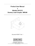
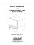
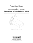
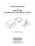
Product User Manual ♦ Model GA4006 3kW Magnetron Head Document # 930035, Rev. 5 P.O. Box 580816 ♦ Modesto, CA 95358 www.2450mhz.com Product User Manual Model GA4006 – 3kW Magnetron Head REV. 4 5 REVISION HISTORY DESCRIPTION Misc. Updates Modified remote control interface Page 2 DATE 13FEB04 28MAR05 APPROVAL JFG JFG WARRANTY Products manufactured and sold by Gerling Applied Engineering, Inc. (“GAE”) are warranted to be free of defects in materials and workmanship under normal use and service for a period of twelve (12) months from the date of original shipment. GAE’s obligation under this warranty is limited to repairing or replacing, at GAE’s option, all non-consumable component parts. Consumable parts are specifically excluded from this warranty and may include, but are not be limited to, magnetrons, fuses, lamps, seals, o-rings, v-belts, and fluids. All warranty repairs are to be done at GAE’s facility or as otherwise authorized by GAE. All shipping charges for warranty repair or replacement are the purchaser’s responsibility unless otherwise agreed to by GAE. This warranty supercedes all other warranties, expressed or implied. No warranty is given covering the product for any particular purpose other than as covered by the applicable product specifications. GAE assumes no liability in any event for incidental or consequential damages, financial losses, penalties or other losses incurred in conjunction with the use of GAE products. DOCUMENT CONVENTIONS NOTE: Means the reader should take note. Notes contain helpful information, suggestions, or references to other sections, chapters, or documents. CAUTION: Means the reader should be careful. You are doing something that might result in equipment damage or loss of data. WARNING: Means danger. A situation exists that could cause bodily injury or death. All personnel must be aware of the hazards involved with high voltage electrical circuitry and high power microwave devices. 2003-2005 Gerling Applied Engineering, Inc. Modesto, CA Product User Manual Model GA4006 – 3kW Magnetron Head Page 3 WARNING All magnetron heads manufactured by GAE, Inc. are capable of producing a microwave field that is potentially hazardous to operating personnel. They must never be connected or operated in a manner that allows a field in excess of 10 milliwatts per square centimeter to be generated in an area accessible to operating personnel. Contact GAE, Inc. for technical support prior to installation and/or operation of these units if there is any question or concern about microwave leakage. All waveguide flange and electrical cable connections throughout the system must be secure prior to operation. Never operate the microwave generator without a properly rated absorbing load attached. To ensure safe operation and prevent microwave leakage, the equipment must be periodically inspected and maintained as required or recommended. 2003-2005 Gerling Applied Engineering, Inc. Modesto, CA Product User Manual Model GA4006 – 3kW Magnetron Head Page 4 TABLE OF CONTENTS EQUIPMENT DESCRIPTION ......................................................................................... 5 General Specifications Mating Connectors (supplied with GA4006) System Block Diagram GA4006 Schematic Diagram 5 6 6 7 INSTALLATION .............................................................................................................. 9 Preliminary Inspection Waveguide Configuration Flange Connections Flange Alignment Pins Water Flow Requirements Water Fitting Connections Power Supply Connections Chassis Ground Connection Remote Control Connections Coupler Power Interface Connections 9 9 9 10 10 10 11 11 12 15 OPERATION................................................................................................................. 16 Basic Operation Fault Condition Microwave Power Control 16 16 17 MAINTENANCE AND CALIBRATION ......................................................................... 18 Magnetron Removal and Replacement 2003-2005 Gerling Applied Engineering, Inc. 18 Modesto, CA Product User Manual Model GA4006 – 3kW Magnetron Head Page 5 EQUIPMENT DESCRIPTION The GA4006 Magnetron Head is specially designed for use with the GA4106 Switch Mode Power Supply. Together with the line power and control cable set provided with the GA4106, this unit makes a completely integrated microwave power generation system ideal for laboratory or stand-alone system applications. Local controls provide complete functionality safely and conveniently near the work area. Microwave output power can be adjusted at either unit or remotely via a fully functional remote control interface. Connections are also provided for interfacing with the model GA3301 Power Coupler Interface (available separately) for monitoring forward and reverse microwave power. Serviceability of the GA4006 was a primary consideration in its design. Removal and replacement of the internal magnetron can be done in minutes using standard tools. The GA4006 is designed to use the Panasonic 2M265 magnetron and can also accommodate other water-cooled magnetrons available from multiple distributors. Contact GAE for more information on magnetron compatibility. A powder-coated steel enclosure provides rugged durability while multiple safety interlocks meet compliance requirements. Convenient mounting holes and brackets facilitate bench-top use or integration into process systems. The simplicity of the GA4006 also facilitates integration with almost any type of custom designed magnetron power supply. Optional features include alternate flange configurations, arc detection and custom (private) labeling and colors. Model GA4006 features the popular WR284 Q-D (quick-disconnect) round flange that uses the convenient single screw clamp (GAE model GA8401) for waveguide connections. General Specifications Output Power (max) 3.0 kW Magnetron Water-cooled Panasonic 2M265 (or equivalent) Output Waveguide WR284 Output Flange UG584/U Frequency 2450 MHz +/- 30 MHz Cooling Water: 1.0 gpm nominal (0.5 gpm min.) flow @ 35 °C max. inlet temp (dew point min. inlet temp), 70 psi max. inlet pressure Air: Provided by internal fans 2003-2005 Gerling Applied Engineering, Inc. Modesto, CA Product User Manual Model GA4006 – 3kW Magnetron Head Page 6 Controls Mw Start (pushbutton) Mw Stop (pushbutton) Mw Power Adjust (10-turn Dial) System Ready (Green LED) HV On (Red LED) Power Adjust Selector (toggle switch) Interlocks Waveguide flange, Access cover, Magnetron over-temperature, Water flow Mating Connectors (supplied with GA4006) High Voltage Lemo series 1Y Remote Control 25-pin male D-subminiature Coupler Power Interface 9-pin male D-subminiature (two connectors provided) System Block Diagram 2003-2005 Gerling Applied Engineering, Inc. Modesto, CA Product User Manual Model GA4006 – 3kW Magnetron Head Page 7 GA4006 Schematic Diagram 2003-2005 Gerling Applied Engineering, Inc. Modesto, CA Product User Manual Model GA4006 – 3kW Magnetron Head Page 8 Outline Drawing 2003-2005 Gerling Applied Engineering, Inc. Modesto, CA Product User Manual Model GA4006 – 3kW Magnetron Head Page 9 INSTALLATION Preliminary Inspection Upon arrival at the installation site the GA4006 magnetron head should be thoroughly inspected for damage or wear caused during shipping. Any visible damage to the packaging material or the magnetron head itself should be noted and reported immediately to the shipping company in accordance with standard claims procedures. The following components are included: a) GA4006 Magnetron Head b) Mating connector set (for remote control and 2x coupler power interface) c) Product User Manual (this document) Waveguide Configuration The GA4006 magnetron head can be connected to and used with any common waveguide component having a compatible flange (see below). Mounting can be in any convenient position and orientation. Ideally, the magnetron head should be connected directly to an isolator (or 3-port circulator and dummy load) to ensure adequate protection of the magnetron from reverse power. Figure 1 illustrates a typical waveguide configuration. Figure 1 – Typical waveguide configuration for process heating. Flange Connections The waveguide flange of the magnetron head must be properly connected to another waveguide component or series of components that provide an adequate load for the microwave power being generated. Bolts and nuts must be installed at all 2003-2005 Gerling Applied Engineering, Inc. Modesto, CA Product User Manual Model GA4006 – 3kW Magnetron Head Page 10 flange bolt holes prior to operation. Model GA4006 is configured with a flange designed for used with the GA8401 Quick-Release clamp when connected to another similarly designed flange. This flange can also be connected to any other standard WR284 round flange (UG-584/U) using suitable fastener hardware. Flange Alignment Pins Each waveguide flange connection that uses a quick-release clamp requires two alignment pins for proper alignment of the adjacent waveguide sections. All GAE waveguide components include one alignment pin for each flange designed for use with quick-release clamps. Alignment pins can be installed into either of two threaded holes centered above and below the waveguide broadwalls. For obvious reasons, the pins must not be installed such that they are opposite each other on mating flanges. Microwave Leakage – Regulatory limits for microwave leakage relate to standards for human safety and interference with other electronic devices. Standards for human safety as adopted by OSHA, the International Electrotechnical Commission (IEC) and other regulatory agencies limit leakage to 5 mW/cm2 measured at 5 cm from the leakage source under normal operating conditions, and 10 mW/cm2 at 5 cm from the source under abnormal operating conditions. The U.S. Federal Communications Commission (FCC) has established regulations limiting the emission of energy at frequencies outside the ISM bands. All GAE waveguide components meets these requirements when properly connected to another waveguide component. Water Flow Requirements A source of water must be connected to the GA4006 that provides an adequate rate of flow. The nominal water flow rate is 1.0 gpm. However, the flow rate must be maintained such that the outlet water temperature does not exceed 150 °F. The minimum allowable flow rate depends on the level of incident microwave power and the inlet water temperature. CAUTION: The minimum inlet temperature of the cooling water must be above the ambient dew point temperature. Allowing the cooling water inlet temperature to drop below the ambient dew point can allow moisture condensation inside the microwave generator and/or waveguide circulator and cause equipment damage. Water Fitting Connections Standard 1/4 NPT female fittings are provided at the front of the GA4006 enclosure. The source of water can be connected to either 2003-2005 Gerling Applied Engineering, Inc. Modesto, CA Product User Manual Model GA4006 – 3kW Magnetron Head Page 11 fitting. It is recommended that a thread sealant such as Teflon pipe thread tape be used to ensure a leak-free connection. Care should be taken to prevent debris from falling into the fitting holes. Since there may be other waveguide components in the system that require cooling water, it may be possible to run all of the water cooling connections in series. In this case, it is recommended that the magnetron head be connected last in the series. Caution should also be exercised to ensure that the resulting water flow rate is adequate for all components. Power Supply Connections All electrical power required for operation of the magnetron head is provided by the model GA4106 power supply. All cable connections are located at one side of the magnetron head. The following describes the basic purpose of each cable required for operation. High Voltage Cable (supplied with GA4006) This shielded cable delivers approximately –5kV DC (with respect to ground) to the magnetron cathode. The cable is permanently fixed to the magnetron head and connects to the GA4106 power supply (connector #3) with a male locking high voltage coaxial connector (P1). A ground return path is provided by the cable shield. Filament and Fan Power Cable (supplied with GA4106) This 7-conductor cable with CPC style connectors delivers power from the GA4106 power supply (connector #4) to the magnetron head (connector J1) for the filament transformer and internal cooling fan. Interlock and Detector Signal Cable (supplied with GA4106) This 14-conductor cable with CPC style connectors delivers the interlock status and (optional) microwave power detector signals power from the magnetron head (connector J2) to the GA4106 power supply (connector #2). Control Signal Cable (supplied with GA4106) This 25-conductor cable with subminiature “D” style connectors delivers the operational control and status signals between the magnetron head (connector J3) to the GA4106 power supply (connector #5). Chassis Ground Connection The chassis of GA4006 magnetron head must be connected directly to the chassis of the magnetron power supply. Connection to the magnetron head chassis is at the ground stud located at the 2003-2005 Gerling Applied Engineering, Inc. Modesto, CA Product User Manual Model GA4006 – 3kW Magnetron Head Page 12 side near the electrical connectors. Connection to the power supply chassis is at the ground stud located at the rear of the chassis. The recommended wire is 12 AWG, UL 1007 (or equivalent) with green or green/yellow insulation. WARNING: Failure to provide an adequate ground connection between the magnetron head and power supply chassis can expose the operator to high voltage and result in severe injury or death. Remote Control Connections The microwave power system can be remotely controlled by means of analog signals or by either one of two digital serial interfaces (RS-232 and RS485). Connections for the serial interfaces are provided at the rear panel of the GA4106 power supply (see GA4106 product user manual for more information). All connections for remote control of the microwave power system using analog signals are made to the GA4006 magnetron head at connector J4. With only minor exceptions, the pinout functionality of connector J4 on the GA4006 is identical to that of connector #5 on the GA4106. Provided with the GA4006 is a mating connector with jumpers that are necessary for system operation in the absence of any other remote control circuitry. CAUTION: Do not attempt to operate the system by connecting remote control directly to connector #5 of the GA4106 power supply. Remote control connections should be made ONLY to connector J4 on the GA4006 magnetron head. Figure 2 below is a diagram of a recommended electrical circuit configuration for basic remote control functionality. While other configurations are possible, the following interface requirements must be met for safe and reliable operation. Several other configurations are possible for analog remote control depending on the desired functionality. See the GA4106 product user manual for a complete description of the analog control interface. 2003-2005 Gerling Applied Engineering, Inc. Modesto, CA Product User Manual Model GA4006 – 3kW Magnetron Head Page 13 Figure 2 – Recommended circuit for basic remote control functionality (connected to J4). Pin 20 – +24 VDC Supply Output This pin provides a regulated +24 VDC which can be used for a variety of control functions in addition to the basic functions described above. The maximum allowed current draw in addition to that required for the basic functions is 100 mA. Pin 19 – Microwave Control Reference Output (+10 VDC) This is a DC voltage generated within the magnetron head for use by a remote power control potentiometer. Because the current output of the voltage source is limited, and for maximum operational stability, this voltage should not be used for any other purpose. Pin 5 – Microwave Power Control Input (0-10 VDC) The level of microwave power delivered from the magnetron head is controlled by varying the voltage present at this pin from 0 to 10 VDC. The use of a precision multi-turn, 10K Ohm potentiometer rated for ½ Watt is recommended for 2003-2005 Gerling Applied Engineering, Inc. Modesto, CA Product User Manual Model GA4006 – 3kW Magnetron Head Page 14 high control resolution and stability. The voltage provided at pin 19 (see above) may be used as a reference, or a separate voltage source referenced to the same ground point can also be used. The toggle switch on the front panel of the magnetron head must be set to “Remote” for this voltage to be functionally active. Pin 18 – Microwave Power Control (Common) This pin is connected internally to ground reference. It should be used only for the power control potentiometer in order to minimize noise and cross talk with other circuitry. Pin 10 – External Interlock Loop (+24 VDC) This signal is present when all internal interlocks of the magnetron power supply are satisfied and the “Mw Stop” switch on the front panel of the magnetron head is not being pressed. This signal must be present for operation of the magnetron head and microwave power generation. Pin 23 – External Interlock Loop (Common) The voltage present at pin 10 must be returned through pin 23 before microwave power can be started. A dry contact interlock device and/or remote “Mw Stop” switch (momentary, normally closed) may be connected in series between pins 10 and 23. Opening either of these two devices will cause microwave power generation to cease. Pin 12 – Mw Ready Signal Voltage Input (+24 VDC) Connecting +24 VDC to this pin provides voltage to the emitter (input) of an opto-isolated transistor used to drive the system “Ready” status indicator. This connection is required for the “Ready” indicator on the GA4006 magnetron head to function. Connecting a momentary “Mw Stop” switch in series provides a convenient means to disable microwave power. NOTE: When remote control is not used, pins 10 and 23 on connector J4 must be connected together and +24 VDC must be supplied to pin 12. The mating connector supplied with the GA4006 includes jumpers for these connections. Pin 24 – Mw Ready Signal Output (+24 VDC) This pin is connected to the collector (output) of the same opto-isolated transistor referred to for pin 12 above. This pin will be at ground potential when the system is in a standby condition and +24 VDC when the magnetron power supply is ready to begin delivering high voltage. Pin 17 – Mw Enable Control Input (+24 VDC) This pin is used to enable microwave power. When all 2003-2005 Gerling Applied Engineering, Inc. Modesto, CA Product User Manual Model GA4006 – 3kW Magnetron Head Page 15 interlocks are satisfied and the system is in “standby” mode, momentarily connecting pin 17 to +24 VDC will enable the power supply to deliver high voltage to the magnetron head. Microwave power will then be generated according to the setting of the microwave power control potentiometer(s). The recommended device for making this connection is a momentary, normally open switch. WARNING: Serious injury and/or death can result from the use of a non-momentary switching device for enabling high voltage and microwave power. The use of a latching device can allow high voltage to be enabled inadvertently and unknowingly, such as can happen upon resetting an interlock device. It is strongly recommended that a momentary switching device be used for the high voltage enable function. Coupler Power Interface Connections The GA4006 magnetron head features connections (J5 and J6) for monitoring forward and reverse microwave power using the GAE model GA3301 Coupler Power Interface (available separately) modules. These modules are powered by +24 VDC from the GA4006 and their output signals are delivered to the GA4106 power supply for display and additional signal processing. Other interface modules having similar input and output specifications can also be used. Figure 3 below illustrates the required interface connections. Figure 3 – Mating connections for the coupler power interface (connected to J5 and J6). NOTE: Pins 7 and 8 on connectors J5 and J6 must be connected together when interface is not used. Mating connectors supplied with the GA4006 include jumpers for these connections. 2003-2005 Gerling Applied Engineering, Inc. Modesto, CA Product User Manual Model GA4006 – 3kW Magnetron Head Page 16 OPERATION Basic Operation Line power is applied to the system when the main power switch on the GA4106 power supply is first turned on. The power supply then enters a “power-on” condition for a few seconds during which internal diagnostic functions are performed. This condition is followed by a “warm-up” period of a few seconds during which the magnetron filament is being heated. The power supply then enters the “standby” condition if all interlocks are satisfied. This “standby” condition is indicated on the front panel of the GA4106 power supply and by illumination of the green “System Ready” indicator located on the front panel of the GA4006 magnetron head. The system is now ready to start generating microwave power. Pressing the “Mw Start” button on the front panel of the magnetron head will enable the delivery of high voltage to the magnetron. This “microwave on” condition is indicated by illumination of the red “Mw On” indicator located on the magnetron head front panel. The actual level of microwave power output will be determined by the setting of the microwave power control as explained below. Pressing the “Mw Stop” button on the magnetron head will stop the generation of microwave power and return the system to the “standby” condition. NOTE: Disabling any of the system interlocks will also immediately terminate microwave power. However, this will place the power supply in the “alarm” condition which requires a repeat of the warm-up period before returning to the “standby” condition. Fault Condition Disabling any of the interlock functions while microwave power is on will immediately turn off microwave power and place the system into a “fault” condition. When in this condition, the “Mw On” indicator will still be on but the “System Ready” indicator will be off. The display on the power supply front panel will provide an indication of the nature of the fault. To clear the fault condition and reset the system, the disabled interlock function (if the cause of the fault) must be restored and the “Mw Stop” switch must be pressed. After a brief timeout period (a few seconds), the system will return to the “standby” condition and allow microwave power to be restarted. 2003-2005 Gerling Applied Engineering, Inc. Modesto, CA Product User Manual Model GA4006 – 3kW Magnetron Head Page 17 Microwave Power Control The level of microwave power generated is determined by the settings of the power control potentiometers or remote analog input signal. Control potentiometers are located on the front panels of both the GA4106 power supply and GA4006 magnetron head. A toggle switch located on the front panel of the magnetron head selects which power control is active. The available settings are “Mag Head” (up position), “Power Supply” (center position) and “Remote Analog” (down position). When “Power Supply” is selected the magnetron head potentiometer and remote analog signal are both disabled. The power control potentiometer on the power supply is always the primary control and will override the settings of the other power controls unless set to zero. This interaction occurs between the power supply potentiometer and either the magnetron head potentiometer or the remote analog control signal. Consider the following examples: 1. If the magnetron head potentiometer is set to 50% power and the power supply potentiometer is set to zero then microwave output power will be 50%. 2. If the power supply potentiometer is then adjusted to 75% then the microwave output power will be 75%. 2003-2005 Gerling Applied Engineering, Inc. Modesto, CA Product User Manual Model GA4006 – 3kW Magnetron Head Page 18 MAINTENANCE AND CALIBRATION The GA4006 magnetron head is designed to be maintenance free with the exception of magnetron replacement. The magnetron is considered a consumable component and has a life expectancy of 3000 to 5000 hours depending on operating conditions and usage. No calibration is necessary. Although the GA4006 magnetron head is a very rugged and stable device, it can be subject to damage due to improper operating conditions or mishandling. If damage occurs, the magnetron head should be returned to GAE for repair. Contact GAE for information on repair services. Magnetron Removal and Replacement The magnetron can be replaced by the user as follows: 1. Turn off the power supply and disconnect line power. 2. Disconnect the source of cooling water, both supply and drain. 3. Turn the four captive cover screws ¼ turn and remove the cover. 4. Remove the brown filament lead insulator block and disconnect the filament transformer and high voltage leads from the magnetron. 5. Loosen the compression fittings located at the side of the magnetron and disconnect the two hoses from the magnetron water fittings. 6. Remove the four #10-32 screws which secure the magnetron to the chassis and carefully lift out the magnetron. 7. Disconnect the two wires connected to the thermal switch mounted to the side of the magnetron. 8. Connect the two thermal switch wires to the contacts of the thermal switch mounted on the new magnetron. 9. Install the new magnetron in the reverse order of removal. 10. Connect the cooling water supply and check for water leaks. 11. Replace the chassis cover. 2003-2005 Gerling Applied Engineering, Inc. Modesto, CA