1
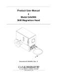
Product User Manual ♦ Model GA4001 Magnetron Head Document # 930014, Rev. 2 January 2001 P.O. Box 580816 ♦ Modesto, CA 95358 www.2450mhz.com Product User Manual Model GA4001 Magnetron Head REV. 1 2 REVISION HISTORY DESCRIPTION PROTOTYPE RELEASE Updated schematic diagram Page 2 DATE 05DEC00 01FEB01 APPROVAL JFG JFG WARRANTY Products manufactured and sold by Gerling Applied Engineering, Inc. (“GAE”) are warranted to be free of defects in materials and workmanship under normal use and service for a period of twelve (12) months from the date of original shipment. GAE’s obligation under this warranty is limited to repairing or replacing, at GAE’s option, all non-consumable component parts. Consumable parts are specifically excluded from this warranty and may include, but are not be limited to, magnetrons, fuses, lamps, seals, o-rings, v-belts, and fluids. All warranty repairs are to be done at GAE’s facility or as otherwise authorized by GAE. All shipping charges for warranty repair or replacement are the purchaser’s responsibility unless otherwise agreed to by GAE. This warranty supercedes all other warranties, expressed or implied. No warranty is given covering the product for any particular purpose other than as covered by the applicable product specifications. GAE assumes no liability in any event for incidental or consequential damages, financial losses, penalties or other losses incurred in conjunction with the use of GAE products. DOCUMENT CONVENTIONS NOTE: Means the reader should take note. Notes contain helpful information, suggestions, or references to other sections, chapters, or documents. CAUTION: Means the reader should be careful. You are doing something that might result in equipment damage or loss of data. WARNING: Means danger. A situation exists that could cause bodily injury or death. All personnel must be aware of the hazards involved with high voltage electrical circuitry and high power microwave devices. 2001 Gerling Applied Engineering, Inc. Modesto, CA Product User Manual Model GA4001 Magnetron Head Page 3 WARNING All magnetron heads manufactured by GAE, Inc. are capable of producing a microwave field that is potentially hazardous to operating personnel. They must never be connected or operated in a manner that allows a field in excess of 10 milliwatts per square centimeter to be generated in an area accessible to operating personnel. Contact GAE, Inc. for technical support prior to installation and/or operation of these units if there is any question or concern about microwave leakage. All waveguide flange and electrical cable connections throughout the system must be secure prior to operation. Never operate the microwave generator without a properly rated absorbing load attached. To ensure safe operation and prevent microwave leakage, the equipment must be periodically inspected and maintained as required or recommended. 2001 Gerling Applied Engineering, Inc. Modesto, CA Product User Manual Model GA4001 Magnetron Head Page 4 TABLE OF CONTENTS EQUIPMENT DESCRIPTION ......................................................................................... 5 General Specifications Mating Connectors (supplied with GA4001) Recommended Alter Components (available separately) Schematic Diagram Outline Drawing 5 6 6 6 7 INSTALLATION .............................................................................................................. 8 Preliminary Inspection Waveguide Configuration Flange Connections Flange Alignment Pins Cooling Air Ventilation Electrical Connections Chassis Ground Connection 8 8 8 9 9 9 11 OPERATION................................................................................................................. 13 Basic Operation Microwave Power Control 13 13 MAINTENANCE AND CALIBRATION ......................................................................... 14 Magnetron Removal and Replacement 2001 Gerling Applied Engineering, Inc. 14 Modesto, CA Product User Manual Model GA4001 Magnetron Head Page 5 EQUIPMENT DESCRIPTION The GA4001 Magnetron Head is specially designed for use with the model SM445 Switching Power Supplies manufactured by Alter. A complete system requires only the GA4001, the SM445 and its mating Line Power/Control cable set (also available separately from Alter), thus greatly simplifying the task of system design and integration. All mating connectors are provided. All controls necessary for operation of the SM445 power supply as well as connections for remote control are provided in the GA4001. The magnetron filament transformer is also packaged inside the unit for added convenience. The complete unit is replaceable by simply disconnecting the waveguide flange and electrical connectors. Removal and replacement of the internal magnetron can be done in less than ten minutes using standard tools. Both units utilize standard air-cooled magnetrons that are readily available from multiple distributors. A powder-coated steel enclosure provides rugged durability while multiple safety interlocks meet compliance requirements. Convenient mounting holes and brackets facilitate bench-top use or integration into process systems. Optional features include alternate flange configurations, arc detection and custom (private) labeling and colors. Model GA4001 features the popular WR284 Q-D (quick-disconnect) round flange that uses the convenient single screw clamp (GAE model GA8401) for waveguide connections. General Specifications Output Power (max) 1.2 kW Magnetron 2M137-IL Output Waveguide WR284 Output Flange UG584/U Frequency 2450 MHz +/- 30 MHz Cooling Forced air by internal fan Controls Mw Start (pushbutton) Mw Stop (pushbutton) Mw Power Adjust (10-turn Dial) HV On (Red LED) Power Adjust Selector (toggle switch) Interlocks Waveguide flange; Access cover; Magnetron over-temperature 2001 Gerling Applied Engineering, Inc. Modesto, CA Product User Manual Model GA4001 Magnetron Head Page 6 Mating Connectors (supplied with GA4001) High Voltage Lemo series 1Y Fan & Filament Power Shell: AMP # 206060-1 Contact: AMP # 66105-4 Power Supply Control Shell: AMP # 211399-1 Contact: AMP # 66105-4 Remote Control Shell: AMP # 211400-1 Contact: AMP # 66103-4 Recommended Alter Components (available separately) Switching Power Supply SM445F.003 Cable Set 44/1384445 Schematic Diagram 2001 Gerling Applied Engineering, Inc. Modesto, CA Product User Manual Model GA4001 Magnetron Head Page 7 Outline Drawing 2001 Gerling Applied Engineering, Inc. Modesto, CA Product User Manual Model GA4001 Magnetron Head Page 8 INSTALLATION Preliminary Inspection Upon arrival at the installation site the GA4001 magnetron head should be thoroughly inspected for damage or wear caused during shipping. Any visible damage to the packaging material or the magnetron head itself should be noted and reported immediately to the shipping company in accordance with standard claims procedures. The following components are included: a) GA4001 Magnetron Head b) Mating connector set (filament & fan power, power supply control and remote control) c) Product User Manual Waveguide Configuration The GA4001 magnetron head can be connected to and used with any common waveguide component having a compatible flange (see below). Mounting can be in any convenient position and orientation. Ideally, the magnetron head should be connected directly to an isolator (or 3-port circulator and dummy load) to ensure adequate protection of the magnetron from reverse power. Figure 1 illustrates a typical waveguide configuration. Figure 1 – Typical waveguide configuration for process heating. Flange Connections The waveguide flanges of the magnetron head must be properly connected to another waveguide component or series of components that provide an adequate load for the microwave power being generated. Bolts and nuts must be installed at all flange bolt holes prior to operation. Model GA4001 is configured 2001 Gerling Applied Engineering, Inc. Modesto, CA Product User Manual Model GA4001 Magnetron Head Page 9 with a flange designed for used with the GA8401 Quick-Release clamp when connected to another similarly designed flange. This flange can also be connected to any other standard WR284 round flange (UG-584/U) using suitable fastener hardware. Flange Alignment Pins Each waveguide flange connection that uses a quick-release clamp requires two alignment pins for proper alignment of the adjacent waveguide sections. All GAE waveguide components include one alignment pin for each flange designed for use with quick-release clamps. Alignment pins can be installed into either of two threaded holes centered above and below the waveguide broadwalls. For obvious reasons, the pins must not be installed such that they are opposite each other on mating flanges. Microwave Leakage – Regulatory limits for microwave leakage relate to standards for human safety and interference with other electronic devices. Standards for human safety as adopted by OSHA, the International Electrotechnical Commission (IEC) and other regulatory agencies limit leakage to 5 mW/cm2 measured at 5 cm from the leakage source under normal operating conditions, and 10 mW/cm2 at 5 cm from the source under abnormal operating conditions. The U.S. Federal Communications Commission (FCC) has established regulations limiting the emission of energy at frequencies outside the ISM bands. All GAE waveguide components meets these requirements when properly connected to another waveguide component. Cooling Air Ventilation The GA4001 magnetron head is air cooled by an internal fan. The ventilation inlet is located at one end of the magnetron head and the exhaust is locate at the opposite end (see outline drawing). At least 2” clearance must be provided at both ventilation ports for adequate cooling. Electrical Connections All electrical power and control signals, except for remote control, are provided by the magnetron power supply. All connectors are located at one side of the magnetron head. The following describes the pinouts for each connector: J1 – Filament and Fan Power Pin 1 – Magnetron head interlock return (ground) This signal is grounded when all three internal magnetron head interlocks are satisfied. Microwave power cannot be generated if any of these interlocks are open. Microwave 2001 Gerling Applied Engineering, Inc. Modesto, CA Product User Manual Model GA4001 Magnetron Head Page 10 power will cease to be generated if an interlock opens during operation. Pin 2 – Chassis ground Pin 3 – L2 input for filament and fan power (208 VAC) This signal is the L2 phase of the power line supplying power to the filament and fan. Pin 4 – L1 input for fan power (208 VAC) This signal is the uncontrolled L1 phase of the power line and supplies power to the fan. Pin 5 – L1 input for filament power (controlled 208 VAC) This signal is the controlled L1 phase of the power line and supplies variable power to the filament transformer. Pin 6 – Ground (used for arc detector signal output) This signal is intended for future use by the output of an arc detector circuit. It must be ground for operation of the magnetron head and generation of microwave power. Pin 7 – No connection J2 – Power Supply Control Pin 1 – Microwave control voltage reference (+10 VDC) This is a DC voltage supplied to the microwave power control potentiometer located in the magnetron head. It can also be used as a voltage reference by an external power control potentiometer. Pin 2 – Microwave control voltage output (0-10 VDC) This is an analog DC voltage proportional to the setting of the microwave control potentiometer located either inside the magnetron head (R1) or remotely. Pin 3 – Anode current sense input (1 V = 200 mA) This signal is generated by the magnetron power supply and is proportional to the magnetron anode current. It is proportional to magnetron output power and thus can used as an indication of microwave power generated by the magnetron head. Pin 4 – Interlock loop input (+12 VDC) This signal is provided by the magnetron power supply when all of its internal interlocks are satisfied. This signal must be present for operation of the magnetron head and microwave power generation. Microwave power will cease to be generated if an interlock opens during operation. Pin 5 – No connection 2001 Gerling Applied Engineering, Inc. Modesto, CA Product User Manual Model GA4001 Magnetron Head Page 11 Pin 6 – High voltage enable output (+12 VDC) This signal must be delivered to the magnetron power supply to start microwave power generation. It is delivered by pressing the “Start” button (S1) on the front panel of the magnetron head and held on by the contacts of a latching relay (K1). The signal is removed and microwave power generation stopped by pressing the “Stop” button. Pin 7 – Chassis ground Pin 8 – No connection J3 – Remote Control Pin 1 – Microwave control voltage reference (+10 VDC) This is a DC voltage supplied for use by a remote power control potentiometer. Pin 2 – Microwave control voltage input (0-10 VDC) This is an analog DC voltage proportional to the setting of the remote microwave control potentiometer. A separate analog control voltage within the same range (such as supplied by a process controller) can also be used. Pin 3 – Anode current sense output (1 V = 200 mA) This signal is generated by the magnetron power supply and is proportional to the magnetron anode current. It is proportional to magnetron output power and thus can used as an indication of microwave power generated by the magnetron head. Pin 4 – Interlock loop output (+12 VDC) This signal is supplied when all internal interlocks of the magnetron power supply and head are satisfied. This signal must be present for operation of the magnetron head and microwave power generation. Pin 5 – Interlock loop return (+12 VDC) This signal is provided as a means to connect an external dry contact interlock. The external interlock connection must be closed for generation of microwave power. Microwave power will cease to be generated if an interlock opens during operation. Pin 6 – Not Used Pin 7 – Chassis ground Chassis Ground Connection The chassis of GA4001 magnetron head must be connected directly to the chassis of the magnetron power supply. Connection to the magnetron head chassis is at the ground stud located at the 2001 Gerling Applied Engineering, Inc. Modesto, CA Product User Manual Model GA4001 Magnetron Head Page 12 side near the electrical connectors. Connection to the power supply chassis is at the ground stud located at the rear of the chassis. The recommended wire is 14 AWG, UL 1007 (or equivalent) with green or green/yellow insulation. WARNING: Failure to provide an adequate ground connection between the magnetron head and power supply chassis can expose the operator to high voltage and result in severe injury or death. 2001 Gerling Applied Engineering, Inc. Modesto, CA Product User Manual Model GA4001 Magnetron Head Page 13 OPERATION Basic Operation All interlocks must be satisfied before operation of the microwave generator can begin. This “standby” condition is indicated by the absence of any lighted indicator lights on the front panel of the magnetron power supply. Pressing the “Start” button on the front panel of the magnetron head will enable magnetron power supply and deliver high voltage to the magnetron. However, The actual level of microwave power output will be determined by the setting of the microwave power control as explained below. Pressing the “Stop” button on the magnetron head, or opening any of the interlocks, will stop the generation of microwave power. Microwave Power Control The level of microwave power generated is determined by the settings of the power control potentiometers or remote analog input signal. Control potentiometers are located on the front panels of both the magnetron power supply and magnetron head. A toggle switch located on the front panel of the magnetron head selects between “Mag Head” (up position), “Power Supply” (center position) and “Remote Analog” (down position) for the location of power control. When “Power Supply” is selected the magnetron head potentiometer and remote analog signal are both disabled. The power control potentiometer on the magnetron power supply is the primary control and will override the settings of the other power controls unless set to zero. For example, if the magnetron head potentiometer is set to 50% power and the magnetron power supply potentiometer is set to zero then microwave output power will be 50%. If the magnetron power supply potentiometer is then adjusted to 75% then the microwave output power will be 75%. The same interaction occurs between the magnetron power supply potentiometer and the remote analog control signal. 2001 Gerling Applied Engineering, Inc. Modesto, CA Product User Manual Model GA4001 Magnetron Head Page 14 MAINTENANCE AND CALIBRATION The GA4001 Magnetron Head is designed to be maintenance free with the exception of magnetron replacement. The magnetron is considered a consumable component and has a life expectancy of 1000 to 3000 hours depending on operating conditions and usage. No calibration is necessary. Although the GA4001 magnetron head is a very rugged and stable device, it can be subject to damage due to improper operating conditions or mishandling. If damage occurs, the magnetron head should be returned to GAE for repair. Contact GAE for information on repair services. Magnetron Removal and Replacement The magnetron can be replaced by the user as follows: 1. Turn off the magnetron power supply and disconnect all electrical connections from the magnetron head. 2. Turn the four captive cover screws ¼ turn and remove the cover. 3. Disconnect the filament leads (located above the fan duct) from the magnetron. 4. Remove the small air duct between the magnetron and the chassis side. 5. Disconnect the two leads connected to the thermal switch mounted to the side of the magnetron. 6. Remove the four nuts (below the magnetron) securing the magnetron to the chassis and carefully lift out the magnetron. 7. Remove the thermal switch from the magnetron and install it onto the new magnetron in the same orientation. 8. Install the new magnetron in the reverse order of removal. 2001 Gerling Applied Engineering, Inc. Modesto, CA