1
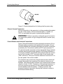
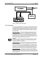
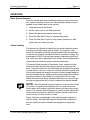
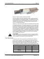
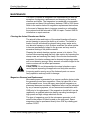
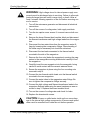
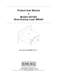
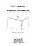
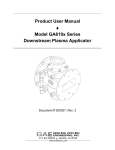
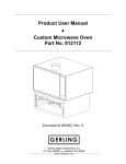
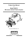
Product User Manual ♦ Model GA5013 Microwave Animal Fixation System Document # 930026, Rev. 10 GERLING Gerling Applied Engineering, Inc. P.O. Box 580816 ♦ Modesto, CA 95358 www.2450mhz.com Product User Manual Model GA5013 – Microwave Animal Fixation System REV. 8 9 10 REVISIONS DESCRIPTION MISC. UPDATES MISC. UPDATES CUPDATES TO INTERLOCK CONNECTION Page 2 930026, Rev. 10 DATE 13FEB06 20DEC06 03APR08 APPROVAL JFG JFG JFG WARRANTY Products manufactured and sold by Gerling Applied Engineering, Inc. (“GAE”) are warranted to be free of defects in materials and workmanship under normal use and service for a period of twelve (12) months from the date of original shipment. GAE’s obligation under this warranty is limited to repairing or replacing, at GAE’s option, all nonconsumable component parts. Consumable parts are specifically excluded from this warranty and may include, but are not be limited to, magnetrons, fuses, lamps, seals, orings, v-belts, and fluids. All warranty repairs are to be done at GAE’s facility or as otherwise authorized by GAE. All shipping charges for warranty repair or replacement are the purchaser’s responsibility unless otherwise agreed to by GAE. This warranty supercedes all other warranties, expressed or implied. No warranty is given covering the product for any particular purpose other than as covered by the applicable product specifications. GAE assumes no liability in any event for incidental or consequential damages, financial losses, penalties or other losses incurred in conjunction with the use of GAE products. DOCUMENT CONVENTIONS NOTE: Means the reader should take note. Notes contain helpful information, suggestions, or references to other sections, chapters, or documents. CAUTION: Means the reader should be careful. You are doing something that might result in equipment damage or loss of data. WARNING: Means danger. A situation exists that could cause bodily injury or death. All personnel must be aware of the hazards involved with high voltage electrical circuitry and high power microwave devices. 2002-2008 Gerling Applied Engineering, Inc. Modesto, CA Product User Manual Model GA5013 – Microwave Animal Fixation System Page 3 930026, Rev. 10 WARNING The microwave system described in this manual is capable of producing a microwave field that is potentially hazardous to operating personnel. The system must never be connected or operated in a manner that allows a field in excess of 10 milliwatts per square centimeter to be generated in an area accessible to operating personnel. Contact GAE, Inc. for technical support prior to installation and/or operation of these units if there is any question or concern about microwave leakage. All electrical cable connections must be secure prior to operation. Never operate the microwave generator without a properly rated absorbing load connected to the waveguide. To ensure safe operation and prevent microwave leakage, the equipment must be periodically inspected and maintained as required or recommended. WARNING All microwave generators manufactured by GAE, Inc. have internal high voltage circuits that are potentially hazardous or lethal to maintenance personnel. All maintenance must be done ONLY by technical personnel fully trained and qualified for work with high voltage circuits. Access covers must never be removed for any reason other than maintenance by qualified technical personnel. The generator must never be operated in any manner other than as described in this user manual. 2002-2008 Gerling Applied Engineering, Inc. Modesto, CA Product User Manual Model GA5013 – Microwave Animal Fixation System Page 4 930026, Rev. 10 TABLE OF CONTENTS DOCUMENT ATTACHMENTS........................................................................................ 4 EQUIPMENT DESCRIPTION.......................................................................................... 5 General Specifications 5 Electrical Specifications Mechanical Specifications System Controls Basic System Components Optional Accessories 5 5 6 6 6 INSTALLATION .............................................................................................................. 7 Preliminary Inspection Mounting Position Waveguide Configuration Flange Connections Animal Chamber Installation Cooling Water Connections Adjustment for Line Voltage Line Power Connection Chassis Ground Connection Control Module and Interlock Connections Timer Programming 7 7 7 8 8 8 9 9 10 10 11 OPERATION ................................................................................................................. 13 Basic System Operation Animal Loading Cycle Timer Preset System Controls Microwave Power Level Switching 13 13 14 15 15 MAINTENANCE ............................................................................................................ 16 Cleaning the Animal Chamber and Holder Magnetron Removal and Replacement Filament Voltage Adjustment 16 16 18 Equipment Required: Procedure: 18 18 DOCUMENT ATTACHMENTS Description Doc. Number Rev. Animal Fixation System Assembly Animal Chamber Assembly, 20-50 gram Animal Chamber Assembly, 50-175 gram Animal Chamber Assembly, 175-450 gram Animal Holder Assembly, 20-50 gram Animal Holder Assembly, 50-100 gram Animal Holder Assembly, 100-175 gram Animal Holder Assembly, 175-325 gram Animal Holder Assembly, 325-450 gram Control Module Schematic Diagram Water Distribution Assembly System Outline Drawing 911020 911305 911021 911022 911306 911023 911024 911025 911026 911095 911097 911368 6 5 5 5 3 3 3 3 3 11 8 1 2002-2008 Gerling Applied Engineering, Inc. Modesto, CA Product User Manual Model GA5013 – Microwave Animal Fixation System Page 5 930026, Rev. 10 EQUIPMENT DESCRIPTION This document describes a 4 kW microwave system designed for the fixation of small laboratory animals such as mice and rats. A high power burst of microwave energy is delivered to the brain area of the animal by means of a specially designed waveguide applicator. Fixation occurs by rapid and extreme heating of the brain tissue while minimizing additional trauma caused to the animal. The system operates at 2.45 GHz at user-selectable microwave output power levels of either 2 kW or 4 kW. Exposure time is also user adjustable via a front panel mounted programmable timer. Standard waveguide components are used to deliver the microwave power to the animal chamber, including a waveguide isolator (circulator and dummy load) to protect the microwave generator from reverse microwave power. Multiple interlock devices protect against hazards caused by incorrect operation. A wide range of animal sizes can be accommodated using a selection of animal holders and application chambers. One animal holder and chamber set is provided with the system and may be selected by the customer. Additional holders and chambers may be purchased separately. General Specifications Electrical Specifications Output Frequency Output Power Magnetron Input Line Power Voltage Phase Current Interlocks Mechanical Specifications Cooling Requirement Water Connections 2002-2008 Gerling Applied Engineering, Inc. 2450 MHz +/- 50 MHz 4 kW, user-selectable between half and full power Panasonic 2M265-M12WJ 60 Hz: 200, 208, 220, 240 VAC, +/- 10% 50 Hz: 200, 230, 240 VAC, +/- 10% Single 30 Amps max. Magnetron temp, Generator access covers, Chamber flanges, Water flow, Connection for external user device Water @ 1 gpm (0.5 gpm min.), 95°F max. inlet temp (dew point minimum inlet temp), 70 psig max. inlet pressure ¼” ID rubber hose provided for water connections Modesto, CA Product User Manual Model GA5013 – Microwave Animal Fixation System Page 6 930026, Rev. 10 Line Power Connection NEMA style L6-30P locking type plug with 6’ power cord Weight (approx.) Microwave Generator: 100 lbs Components and accessories: 35 lbs System Controls NOTE: Unless otherwise indicated, all controls are located on the control module only. Microwave Start Pushbutton Microwave Stop Pushbutton (control module and generator) High/Low Select Pushbutton Exposure Timer Programmable digital timer, .01 sec increments Indicators System Ready (“Mw Start” switch) Microwave On (“Mw Stop” switch) High Power Low Power Mw Power (generator only) Basic System Components Microwave Generator System Control Module 3-Port Circulator Short Dummy Load Waveguide Bend w/View Tube Animal Chamber (size specified by customer) Animal Holder (size specified by customer) Set of waveguide clamps Set of connecting cables and hoses Product User Manual Optional Accessories Animal Chamber, 50-175 gram, p/n 911021 Animal Chamber, 175-450 gram, p/n 911022 Animal Holder, 50-100 gram, p/n 911023 Animal Holder, 100-175 gram, p/n 911024 Animal Holder, 175-325 gram, p/n 911025 Animal Holder, 325-450 gram, p/n 911026 2002-2008 Gerling Applied Engineering, Inc. Modesto, CA Product User Manual Model GA5013 – Microwave Animal Fixation System Page 7 930026, Rev. 10 INSTALLATION Preliminary Inspection Upon arrival at the installation site the system should be thoroughly inspected for damage or wear caused during shipping. Any visible damage to the packaging material or the system components should be noted and reported immediately to the shipping company in accordance with standard claims procedures. Mounting Position The system is supplied as an integral assembly consisting of the microwave generator, control module, waveguide components and animal chamber. The system must be mounted upright on a level surface capable of supporting its weight. Waveguide Configuration The system includes three waveguide components used to safely deliver microwave power from the generator to the animal chamber. Figure 1 below illustrates the waveguide configuration. Included in the configuration are a 3-port circulator and dummy load which together protect the generator (specifically the internal magnetron) from the damaging effects of reverse power. Also included is a waveguide bend section which orients the animal chamber in a position convenient for the system operator. This waveguide section has a viewing tube which allows the operator to observe the animal to ensure proper positioning prior to fixation. Figure 1, Waveguide configuration and cooling water connections. 2002-2008 Gerling Applied Engineering, Inc. Modesto, CA Product User Manual Model GA5013 – Microwave Animal Fixation System Page 8 930026, Rev. 10 Flange Connections All waveguide components used in the system must be properly connected to each other for safe operation. The three waveguide components described above are connected to each other using standard threaded fastener hardware to form an integral assembly. This assembly is then connected to the microwave generator using the GA8401 quick-release waveguide clamp. Two alignment pins are supplied with this flange connection, one on each mating waveguide flange, to ensure proper alignment of the waveguide sections. Alignment pins are not required for the waveguide flange connections which use standard hardware. Animal Chamber Installation The animal chamber assembly consists of two main sections, the applicator and body tube. These two sections are connected together using a larger size quick-release clamp (similar to the GA8401) to form the animal chamber assembly. This assembly is then connected to the waveguide bend section using another GA8401 quick-release clamp. Flange interlock switches are installed at both ends of the animal applicator section to prevent system operation if either of these flanges is not properly connected. CAUTION: Do not loosen the locking nut or attempt to adjust the tuning screw located on the top of the animal applicator. Adjusting the screw setting will alter the calibration of the animal chamber and result in faulty operation. Cooling Water Connections A source of filtered water must be connected to the system that provides a nominal flow rate of 1.0 gpm (0.5 gpm minimum), 70 psig max. inlet pressure and 95°F max. inlet temperature. Figure 1 above illustrates the water connections. The water supply and drain connections can be made to ¼” ID rubber hoses provided with the system. All other hoses and connection fittings are also provided. CAUTION: The minimum inlet temperature of the cooling water must be above the ambient dew point temperature. Allowing the cooling water inlet temperature to drop below the ambient dew point can allow moisture condensation inside the microwave generator and/or waveguide circulator and cause equipment damage. CAUTION: Water should be drained from the unit during extended periods of non-use to prevent freezing. Failure to adequately drain the cooling system can result in damage due to the expansion of freezing water. 2002-2008 Gerling Applied Engineering, Inc. Modesto, CA Product User Manual Model GA5013 – Microwave Animal Fixation System Page 9 930026, Rev. 10 CAUTION: Inlet water should be filtered to prevent clogging of the internal water lines. The most common failure due to clogging is a malfunction of the water flow interlock switch. Running the cooling water temporarily in the opposite direction can help to unclog the lines. Adjustment for Line Voltage The microwave generator is configured at the factory to operate within a range of line voltages for a specific line frequency (either 60 Hz or 50 Hz). To accomplish this, a series of voltage taps are provided that allow the generator to operate within +/- 10% of the nominal tap voltage. The following is a list of tap voltages and respective operating voltage range. Tap Voltage (VAC) 200 208 (60 Hz only) 220 (60 Hz only) 230 (50 Hz only) 240 Operating Voltage Range 180-220 187-229 198-242 207-253 216-264 The voltage taps are located on the main (high voltage) transformer inside the microwave generator. Generally, the initial factory set up is according to the line voltage and frequency at the customer’s facility. However, the user is advised to measure the facility line voltage and ensure the correct tap is selected prior to operation. WARNING: Turn off microwave power and disconnect all electrical connections before adjusting the line voltage taps. Failure to disconnect line power can expose the operator to high voltage and result in severe injury or death. CAUTION: After selecting the proper line voltage tap, the filament voltage should be checked and, if necessary, adjusted according the procedure provide in the Maintenance section of this manual. Improperly adjusted filament voltage can result in premature magnetron failure. Line Power Connection Main line power is connected using a 6-foot type SO power line cord and NEMA L6-30P twist-lock type plug provided with the generator. Wiring is single phase, 2-wire plus ground. The circuit supplying voltage to the receptacle must be rated for at least 30 Amps of continuous current draw. Although a 30 Amp circuit breaker is provided inside the generator, the line power supply circuit should also be fused or circuit breaker protected for the same rating. 2002-2008 Gerling Applied Engineering, Inc. Modesto, CA Product User Manual Model GA5013 – Microwave Animal Fixation System Page 10 930026, Rev. 10 Figure 2, Contact designations for locking style line power plug. Chassis Ground Connection Ground connection to the generator is at the ground stud located at the rear of the chassis. The recommended wire is 14 AWG, UL 1007 (or equivalent) with green or green/yellow insulation. WARNING: Failure to provide an adequate ground connection can expose the operator to high voltage and result in severe injury or death. Control Module and Interlock Connections Figure 3 below illustrates the system electrical connections. All cables and mating connectors are supplied with the system. All connections between the microwave generator and control module are provided by the 14-conductor cable and CPC style connector P1. The animal chamber assembly includes waveguide flange interlock switches which prevent system operation if the animal chamber is not properly installed. The interlock wiring harness has two connectors, a 4-pin circular (“CPC”) connector and a 2-pin header style (“MR”) connector. The 4-pin connector attaches to connector J1 on the rear panel of the control module. The customer may connect an external interlock device which will prevent the system from operating if the interlock function is not satisfied. The interlock device must be a dry contact switch closure rated for at least 12 VDC. Connection of the external interlock is to the 2-pin connector at the end of a short cable bundled with the animal chamber interlock harness. A mating connector with jumpered contacts is provided, allowing the customer to splice in the external interlock wiring. 2002-2008 Gerling Applied Engineering, Inc. Modesto, CA Product User Manual Model GA5013 – Microwave Animal Fixation System Page 11 930026, Rev. 10 Figure 3, System Electrical Diagram Timer Programming The control module includes a multifunction digital timer which can be programmed directly from the front panel. The timer has been preprogrammed for operating functionality best suited for the system. Thus, the user need only enter the preset values for the desired cycle time. Cycle Time Range – The timer has been preprogrammed at the factory for a cycle range of 0.01 to 99.99 seconds. The operator may adjust the cycle time to any value within this range in 0.01 second increments. However, the practical range for good fixation performance is in the range of 0.5 to 3 seconds depending on animal size and selected microwave power level. NOTE: To prevent operation for extended periods, the system has been designed to terminate the cycle automatically after 10 seconds of continuous operation. Cycle Time Preset – Use the four numeric keys on the timer front panel to set the cycle time preset. Pressing a numeric key will increment the value of the corresponding digit in a cyclical manner from 0 to 9. The preset value is displayed by the small set of digits at the bottom of the LCD display. Once set, the value will be retained for each consecutive cycle until readjusted by the operator. Cycle Time Display – The large set of digits on the LCD display represent the time remaining in the cycle. These digits count down from the preset value to zero while the system is in “operate” mode (see next section). 2002-2008 Gerling Applied Engineering, Inc. Modesto, CA Product User Manual Model GA5013 – Microwave Animal Fixation System Page 12 930026, Rev. 10 WARNING: The timer has been preprogrammed with a security lock-out which prevents the operator from accessing other timer programming functions. Reprogramming the timer for a different operating function can result in faulty and possibly unsafe system operation. Do not attempt to defeat the security lock-out. Contact GAE for service if timer function reprogramming becomes necessary. 2002-2008 Gerling Applied Engineering, Inc. Modesto, CA Product User Manual Model GA5013 – Microwave Animal Fixation System Page 13 930026, Rev. 10 OPERATION Basic System Operation Once the system has been installed according to the previous section, system operation involves the following basic steps (to be explained in more detail later in this section): 1. Load the animal to be fixated. 2. Set the cycle timer to the desired preset. 3. Select the desired microwave power level. 4. Press the “Mw Start” button to operate the system. 5. Press the “Mw Stop” button to stop system operation or after cycle time-out to reset the timer. Animal Loading The animal to be fixated is loaded into the animal chamber assembly using a specially design plastic holder. The purpose of this holder is to precisely locate the animal’s head inside the applicator to expose it to a highly concentrated field of microwave energy. Approximately 95-99% of the delivered power is absorbed by the animal, while very little is absorbed by the holder. Accurate placement of the animal is critical for proper system performance. The animal holder consists of three parts: body, retainer and pin. Insert the animal by first removing the retainer and pin from the body. Coax the animal into the body head-first and allow the animal to crawl as far in as it can. Insert the retainer behind the animal with the flat end against the animal’s rear and rounded straight edge positioned towards the tail. Applying mild pressure against the animal may be necessary to encourage it to crawl farther into the tube. When the animal is properly situated inside the body, insert the pin through an appropriate set of holes to capture the retainer handle. NOTE: Often the animal is quite reluctant to crawl into the holder on its own. A simple trick to facilitate this is to cover the animal holder with a dark opaque cloth while leaving the entry opening exposed. The animal’s natural tendency to crawl into dark spaces will make the animal holder an attractive retreat. Quickly insert the retainer and pin once the animal is inside. Figure 4 below is a photograph of an animal properly inserted inside the holder. Note that the animal’s head should completely inside the small end section beneath the wedge and reasonably level. 2002-2008 Gerling Applied Engineering, Inc. Modesto, CA Product User Manual Model GA5013 – Microwave Animal Fixation System Page 14 930026, Rev. 10 Figure 4, Animal properly inserted into holder. Once the animal is securely inside the holder, carefully insert the holder head-first into the animal chamber. The head section of the animal holder fits into a small diameter hole at the far end of the chamber body tube section. The holder must be inserted all the way in for proper performance. Alignment of the animal holder within the chamber is also important for proper performance. The holes along the top of the holder body should be in line with a scribe mark on the top and end of the body tube section. The operator may also check alignment by observing the animal inside the chamber through the viewing tube located in the waveguide bend section. A penlight is provided with the system to assist in viewing by inserting it into the vertical tube on top of the animal chamber. Ideally, the holder should be level and animal’s eyes symmetrically positioned. CAUTION: Avoid system operation without a properly loaded animal. The absence of a suitable load inside the chamber can result in damage to the chamber and/or animal holder. Cycle Timer Preset The preset value of the cycle timer must be determined and set prior to system operation. The optimal preset value may vary depending on microwave power level and animal size. Too high or too low of a value may yield poor results. The following table is provided to assist the operator in determining the optimal preset value. Table 1 – Recommended cycle timer preset values (sec) Animal weight (gm) Low Power High Power 20-50 50-100 100-175 175-325 325-450 2002-2008 Gerling Applied Engineering, Inc. Modesto, CA Product User Manual Model GA5013 – Microwave Animal Fixation System Page 15 930026, Rev. 10 System Controls Line power is applied to the system by turning on the main circuit breaker located on the rear panel of the microwave generator. There is a brief delay period of approximately 10 seconds for generator warm-up. System operation can begin once the warm-up delay has timed out and all interlocks are satisfied (see previous section). At this point the system is in “standby” mode as indicated by illumination of the “Mw Start” pushbutton switch located on the control module front panel. Power will also be applied to the cycle timer allowing it to be programmed. Pressing the “Mw Start” pushbutton will enable the microwave generator and cause microwave power to be generated at a power level corresponding to the power level setting. The system is now in “operate” mode as indicated by illumination of the “Mw Stop” pushbutton switches located on the microwave generator and control module. The system will remain in “operate” mode until one of the following events occurs: a) The cycle timer has timed out. In this case the system and timer must be reset by pressing the “Mw Stop” button on the control module. The system is returned to “standby” mode and will then be ready for the next operation cycle. b) Either of the two “Mw Stop” pushbuttons is pressed. In this case the system and timer are automatically reset to “standby” mode and will be ready for the next operation cycle. c) An interlock device opens. In this case the microwave generator will immediately stop delivering microwave power, but the cycle timer will continue to operate until it has timed out. Pressing the “Mw Stop” pushbutton either before or after the timer has timed out will reset the timer, but the system will not return to “standby” mode until the all interlock devices are satisfied. NOTE: At the end of a normal operating cycle after the cycle timer has timed out, the “Mw Stop” button must be pressed to reset the timer. Microwave Power Level Switching The level of microwave power generated can be switched between low (half) and high (full) power by pressing the “Push to Select” pushbutton switch on the control module front panel. However, the power level setting can not be changed while the generator is in “operate” mode. Upon system power-up, the power level setting is the same as before the previous power-down. 2002-2008 Gerling Applied Engineering, Inc. Modesto, CA Product User Manual Model GA5013 – Microwave Animal Fixation System Page 16 930026, Rev. 10 MAINTENANCE The GA5013 system is designed to be maintenance free with the exception of magnetron replacement and cleaning of the animal chamber and holder. The magnetron is considered a consumable component and has a life expectancy between 1000 to 5000 hours. Refer to the section below for magnetron replacement instructions. In the event of damage due to improper operation or mishandling, the system should be returned to GAE for repair. Contact GAE for information on repair services. Cleaning the Animal Chamber and Holder The animal holder and interior of the animal chamber will require period cleaning to prevent the build-up of residue. The holder is made of acrylic and should be cleaned using soapy water and a non-abrasive sponge or cloth. Surface scratches can allow residue to become permanently lodged in the grooves and may result in excessive heating of the plastic material. Cleaning the animal chamber requires access to its interior. This involves disconnecting only the body tube section by loosening the clamp screw and removing the clamp. Once the two sections are separated, the interior surfaces can be cleaned using soapy water and a non-abrasive sponge. Minor amounts of residue lodged in the interior crevices will not affect performance. CAUTION: Do not disassemble the animal chamber components beyond separating the applicator and body tube sections. Loosening and/or moving any of the fastened parts can cause faulty operation and may result in damage. Magnetron Removal and Replacement Microwave power is generated by a vacuum oscillator device inside the generator known as a magnetron. Given its typical life of several thousand hours, it may be many years before magnetron replacement becomes necessary. Magnetron failure can be indicated by any of several symptoms, so we recommend consultation with GAE prior to its replacement. If the magnetron should fail it can be replaced by a qualified technician having a working knowledge of high power and high voltage electrical circuits. The type of magnetron used in the microwave generator is indicated on the product ID label located on the rear panel. Spare magnetrons can be purchased directly from GAE by ordering part number 010207. 2002-2008 Gerling Applied Engineering, Inc. Modesto, CA Product User Manual Model GA5013 – Microwave Animal Fixation System Page 17 930026, Rev. 10 WARNING: High voltage stored in internal power supply components must be discharged prior to servicing. Failure to allow adequate discharge time can result in sever injury or death. Allow at least 5 minutes following operation of the unit before removing covers for service. 1. Turn off the microwave generator and disconnect all electrical connections. 2. Turn off the source of cooling water, both supply and drain. 3. Turn the ten captive cover screws ¼ turn and remove both covers. 4. Remove the brown filament lead insulator block and disconnect the filament transformer and high voltage leads from the magnetron. 5. Disconnect the two water tubes from the magnetron water fittings by loosening the compression fittings. Some bending of the tubes may be necessary but should be minimized. 6. Disconnect the two leads connected to the thermal switch mounted to the side of the magnetron. 7. Remove the four nuts (below the magnetron) securing the magnetron to the waveguide mounting bracket and carefully lift out the magnetron. 8. Carefully insert the new magnetron into the waveguide, being careful to avoid contact with the ceramic antenna dome. 9. Secure the magnetron in place using the four mounting nuts removed in step 6. 10. Connect the two thermal switch leads onto the thermal switch mounted to the new magnetron. 11. Connect the water tubes to the magnetron water fittings. Be sure to tighten the compression fittings securely. 12. Connect the high voltage and filament transformer leads to the magnetron filament leads using the same hardware as was removed in step 3. Replace the brown insulator block. 13. Turn on the source of cooling water and check for leaks. 14. Replace the chassis side covers. CAUTION: Excess or spilled water inside unit can cause damage to the internal high voltage components. All excess and spilled water must be removed from inside the unit before operation. 2002-2008 Gerling Applied Engineering, Inc. Modesto, CA Product User Manual Model GA5013 – Microwave Animal Fixation System Page 18 930026, Rev. 10 Filament Voltage Adjustment After replacing the magnetron, the voltage delivered to its filament terminals must be adjusted to conform to the magnetron manufacturer’s specification and ensure long magnetron life. Improperly adjusted filament voltage can result in premature magnetron failure. Equipment Required: 1. 0-10 VDC iron-vane (or other true RMS type) voltmeter with full insulation rated for 15 kVDC minimum. GAE model GA3201 Isolated Filament Voltmeter meets this requirement. 2. #2 Phillips screwdriver Procedure: 1. Turn off the generator and disconnect all electrical connections. 2. Remove the brown filament lead insulator block at the side of the magnetron. 3. Connect the leads of the isolated filament voltmeter to the magnetron filament lead connectors. 4. Connect a suitable waveguide load to the output flange of the microwave generator (see the Installation section of this manual). WARNING: High voltage will be present and exposed during the next step. All personnel MUST remain a safe distance away from the exposed high voltage during operation of the microwave generator. Failure to heed this warning can result in sever injury or death. 5. Turn on the microwave generator to place the system into “stand-by” mode. Do not turn on microwave power yet. 6. The reading on the filament voltmeter should be 4.5 +/- 0.5 Volts. If the reading is not within this range then it may be an indication of a failure of the filament control circuit and must be corrected before proceeding with the next step. 7. Turn on microwave power to place the system into “operate” mode and observe the filament voltmeter reading. If it is 1.5 +/0.3 Volts then skip the following step. 8. Turn off the microwave generator and unplug the line power connector. Loosen the tap screw on the high power resistor located on the chassis bottom next to the magnetron. Move the tap as necessary to adjust the filament voltage until it is within the range specified in the previous step. Tighten the resistor tap, plug in the line power connector and turn on the microwave 2002-2008 Gerling Applied Engineering, Inc. Modesto, CA Product User Manual Model GA5013 – Microwave Animal Fixation System Page 19 930026, Rev. 10 generator to place it in “stand-by” mode. Repeat the previous step. 9. Turn off the microwave generator, replace the brown filament lead insulator block and replace the side access covers. 2002-2008 Gerling Applied Engineering, Inc. Modesto, CA