1
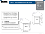
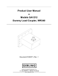
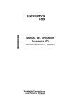
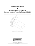
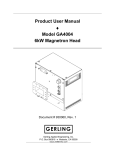
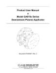
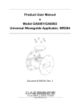
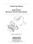
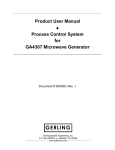
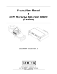
Product User Manual ♦ Basic Waveguide Tuner Document # 930018, Rev. 3 GERLING Gerling Applied Engineering, Inc. P.O. Box 580816 ♦ Modesto, CA 95358 www.2450mhz.com Product User Manual Model GA10xx Series Basic Waveguide Tuner REV. 2 3 REVISION HISTORY DESCRIPTION Added sections stub adjustment and repair Added outline drawings and Smith Chart Page 2 930018, Rev. 3 DATE 30JAN05 28FEB08 APPROVAL JFG JFG WARRANTY Products manufactured and sold by Gerling Applied Engineering, Inc. (“GAE”) are warranted to be free of defects in materials and workmanship under normal use and service for a period of twelve (12) months from the date of original shipment. GAE’s obligation under this warranty is limited to repairing or replacing, at GAE’s option, all non-consumable component parts. Consumable parts are specifically excluded from this warranty and may include, but are not be limited to, magnetrons, fuses, lamps, seals, o-rings, v-belts, and fluids. All warranty repairs are to be done at GAE’s facility or as otherwise authorized by GAE. All shipping charges for warranty repair or replacement are the purchaser’s responsibility unless otherwise agreed to by GAE. This warranty supercedes all other warranties, expressed or implied. No warranty is given covering the product for any particular purpose other than as covered by the applicable product specifications. GAE assumes no liability in any event for incidental or consequential damages, financial losses, penalties or other losses incurred in conjunction with the use of GAE products. DOCUMENT CONVENTIONS NOTE: Means the reader should take note. Notes contain helpful information, suggestions, or references to other sections, chapters, or documents. CAUTION: Means the reader should be careful. You are doing something that might result in equipment damage or loss of data. WARNING: Means danger. A situation exists that could cause bodily injury or death. All personnel must be aware of the hazards involved with high voltage electrical circuitry and high power microwave devices. 2003-2008 Gerling Applied Engineering, Inc. Modesto, CA Product User Manual Model GA10xx Series Basic Waveguide Tuner Page 3 930018, Rev. 3 WARNING All 3-stub tuners manufactured by GAE, Inc. are intended for use with other equipment capable of producing a microwave field that is potentially hazardous to operating personnel. They must never be connected or operated in a manner that allows a field in excess of 10 milliwatts per square centimeter to be generated in an area accessible to operating personnel. Contact GAE, Inc. for technical support prior to installation and/or operation of these units if there is any question or concern about microwave leakage. All waveguide flange and electrical cable connections throughout the system must be secure prior to operation. Never operate the microwave generator without a properly rated absorbing load attached. To ensure safe operation and prevent microwave leakage, the equipment must be periodically inspected and maintained as required or recommended. 2003-2008 Gerling Applied Engineering, Inc. Modesto, CA Product User Manual Model GA10xx Series Basic Waveguide Tuner Page 4 930018, Rev. 3 TABLE OF CONTENTS EQUIPMENT DESCRIPTION.......................................................................................... 5 General Specifications Outline Drawings 5 6 INSTALLATION .............................................................................................................. 7 Preliminary Inspection Waveguide Configuration Flange Connections Flange Alignment Pins 7 7 7 8 OPERATION ................................................................................................................... 9 Basic Operation Stub Response Stub Tension Nuts Stub Retraction Indicator Standard Tuning Procedure False Null High Power Operation 9 9 10 10 11 12 12 MAINTENANCE AND CALIBRATION.......................................................................... 13 Tuning Stub Removal and Replacement Disassembly Reassembly 2003-2008 Gerling Applied Engineering, Inc. 13 13 13 Modesto, CA Product User Manual Model GA10xx Series Basic Waveguide Tuner Page 5 930018, Rev. 3 EQUIPMENT DESCRIPTION The model GA10xx series of Basic Waveguide Tuners are designed for load impedance matching in high power microwave heating systems. Their simple yet rugged design makes these tuners ideal for a variety of laboratory, production and OEM applications. Two stub configurations are available. The 3-stub models have stubs spaced at 1/4-guide wavelength intervals and offset 1/16guide wavelength from center. The 4-stub models have stubs spaced at 1/8-guide wavelength intervals and offset 1/32 guide wavelength from center. In both cases, the offsets provide the capability of tuning a broader range of impedances than standard tuners having no offset.. The stub housings are designed with 1/4-wave reactive chokes allowing use in high “Q” applications. Spring-loaded locking nuts secure the stubs in the position while allowing fine adjustment under high power operation. Construction of the GA10xx series basic tuners is dip brazed aluminum waveguide and brass tuning stubs. Model GA1010 features the popular WR284 Q-D (quick-disconnect) round flange that uses the convenient single screw clamp (model GA8401) for waveguide connections. General Specifications Frequency 2450 MHz nominal GA1004 GA1005 GA1006 GA1010 Power 3 kW 6 kW 10 kW 3 kW Waveguide WR284 WR340 WR430 WR284 Flanges UG1725/U UG554/U Construction Dip brazed aluminum waveguide, brass stubs Finish Clear chemical film, black paint 2003-2008 Gerling Applied Engineering, Inc. UG437B/U UG584/U Modesto, CA Product User Manual Model GA10xx Series Basic Waveguide Tuner Page 6 930018, Rev. 3 Outline Drawings 2003-2008 Gerling Applied Engineering, Inc. Modesto, CA Product User Manual Model GA10xx Series Basic Waveguide Tuner Page 7 930018, Rev. 3 INSTALLATION Preliminary Inspection Upon arrival at the installation site the GA10xx series tuner should be thoroughly inspected for damage or wear caused during shipping. Any visible damage to the packaging material or the tuner itself should be noted and reported immediately to the shipping company in accordance with standard claims procedures. The following components are included: a) GA10xx series Basic Waveguide Tuner b) Product User Manual Waveguide Configuration The waveguide tuner can be connected to and used with any common waveguide component having a compatible flange (see below). Mounting can be in any convenient position and orientation with either flange positioned towards the process load. Ideally, the tuner should be located as close to the process load as possible. Figure 1 illustrates a typical waveguide configuration. Figure 1, Typical waveguide configuration for process load impedance tuning. Flange Connections Both flanges of the waveguide tuner must be properly connected to another waveguide component. Bolts and nuts must be installed at all flange bolt holes on both flanges prior to operation. Model GA1010 is available with flanges designed for use with the GA8410 Quick-Release clamp when connected to another similarly designed flange. These flanges can also be connected to any other 2003-2008 Gerling Applied Engineering, Inc. Modesto, CA Product User Manual Model GA10xx Series Basic Waveguide Tuner Page 8 930018, Rev. 3 standard WR284 round flange (UG-584/U) using suitable fastener hardware. Flange Alignment Pins Each waveguide flange connection that uses a quick-release clamp requires two alignment pins for proper alignment of the adjacent waveguide sections. All GAE waveguide components include one alignment pin for each flange designed for use with quick-release clamps. Alignment pins can be installed into either of two threaded holes centered above and below the waveguide broadwalls. For obvious reasons, the pins must not be installed such that they are opposite each other on mating flanges. Microwave Leakage – Regulatory limits for microwave leakage relate to standards for human safety and interference with other electronic devices. Standards for human safety as adopted by OSHA, the International Electrotechnical Commission (IEC) and other regulatory agencies limit leakage to 5 mW/cm2 measured at 5 cm from the leakage source under normal operating conditions, and 10 mW/cm2 at 5 cm from the source under abnormal operating conditions. The U.S. Federal Communications Commission (FCC) has established regulations limiting the emission of energy at frequencies outside the ISM bands. All GAE waveguide components meets these requirements when properly connected to another waveguide component. 2003-2008 Gerling Applied Engineering, Inc. Modesto, CA Product User Manual Model GA10xx Series Basic Waveguide Tuner Page 9 930018, Rev. 3 OPERATION Basic Operation The most common intended function of the GA10xx series tuners is to provide an impedance match to the process load. Operating the waveguide tuner for this purpose is a procedure involving the adjustment of one or more tuning stubs while monitoring power reflected from the process load. However, predicting the best stub or combination of stubs to adjust is nearly impossible without the aid of additional impedance analysis equipment. Thus, choosing which stub to adjust at any point during the tuning procedure is a matter of either trial and error or prior experience with a given load. Note that, in most cases of impedance matching, no more than two stubs are required to achieve an impedance match. Three stubs are provided with the GA10xx series tuners (four stubs with other models) to cover a broader range of possible impedances. However, if difficulty is experienced in achieving a match, a possible solution is to reverse the orientation of the tuner in the waveguide setup (turn the tuner end for end) so as to effectively shift the stub positions by 1/2 of a stub spacing. CAUTION: Care must be taken to avoid operating the microwave generator at power levels exceeding the rating of the tuner. Excessive power levels can cause damage to the tuning stubs. Stub Response Figure 3 is a Smith Chart representation of the magnitude and phase response of each tuning stub. Note that stubs 1 and 3 follow the same curve when operated individually, which is consistent with their 1/2-guide wavelength separation. Similarly, stub 2 follows a curve which is 1/4-guide wavelength apart from that of stubs 1 and 3. Operating any two stubs simultaneously will generate a similar curve at some other relative phase angle. By rotating the GA10xx tuner end for end, the reference position (stub 1 centerline) will rotate 90 degrees (1/8-guide wavelength) around the Smith Chart. The direction of rotation of the reference position will be clockwise if stub 2 is moved towards or away from the generator and counterclockwise if moved away from the generator. NOTE: Either one of the two outside stubs can be defined as stub 1. Stub 2 is always the middle stub. 2003-2008 Gerling Applied Engineering, Inc. Modesto, CA Product User Manual Model GA10xx Series Basic Waveguide Tuner Page 10 930018, Rev. 3 Figure 3, Smith Chart representation of the magnitude and phase response of tuning stubs used in GA10xx tuners. Stub Tension Nuts Each tuning stub is equipped with a spring-loaded nut that applies constant tension to the tuning stub. This tensioning reduces the electrical contact resistance between mating screw threads which then minimizes power losses and stub heating during high power operation. CAUTION: The tension nuts must be engaged while adjusting the tuning stubs during high power operation. Adjusting the tuning stub during high power operation while the tension nut is loose can damage the stub threads due to arcing and/or burning. Stub Retraction Indicator Each tuning stub is marked with a groove that provides an indication of the position of maximum allowable retraction. This groove is located roughly mid-way along the stub threads as shown in Figure 2. When the groove is positioned at the top of the stub tension nut the end stub is approximately flush with the inside surface of the waveguide wall. 2003-2008 Gerling Applied Engineering, Inc. Modesto, CA Product User Manual Model GA10xx Series Basic Waveguide Tuner Page 11 930018, Rev. 3 Figure 2, Basic tuner stubs in fully retracted position. CAUTION: While operating under microwave power, do not adjust the tuning stub to a position where the indicator groove is above the top surface of the stub tension nut. Doing so may allow the tuning stub to become disengaged from the screw threads and allow excessive microwave leakage. Standard Tuning Procedure A recommended tuning procedure for first-time matching of a given load is as follows: 1. Begin with all stubs adjusted to the fully extracted position (fully clockwise). 2. Slowly adjust stub 1 while monitoring the level of reflected power. If reflected power increases then return the stub to its original position and proceed to step 6. If reflected power decreases then continue adjusting until the reflected power stops decreasing. 3. Slowly adjust stub 2 while monitoring reflected power. If reflected power increases then return the stub to its original position and try again with stub 3. If reflected power decreases then continue adjusting until the reflected power stops decreasing. (Repeat this step again with stub 4 on 4-stub models.) 4. Return to stub 1 and adjust in whatever direction causes reflected power to decrease. Continue adjusting until reflected power stops decreasing. 2003-2008 Gerling Applied Engineering, Inc. Modesto, CA Product User Manual Model GA10xx Series Basic Waveguide Tuner Page 12 930018, Rev. 3 5. Repeat steps 2 through 4 until reflected power no longer decreases by adjusting stubs 1 and 2. Make note of the stub positions and the level of reflected power. 6. Return all stubs and repeat the process except to start with a different stub. Continue until reflected power has again been minimized and make note of the stub positions and reflected power level. Compare to the results obtained in step 5. 7. Repeat step 6 as many times as necessary using different stub combinations until reflected power has been reduced to a satisfactory minimum. False Null The above procedure can sometimes lead to a false indication of reflected power minimization. That is, it may appear that adjusting any one stub will result in an increase of reflected power. This “false null” can be overcome by detuning one stub and retuning another in order to find another null using a different combination of stubs. High Power Operation The GA10xx series tuners are designed for continuous use at microwave power levels up to 10kW depending on model. However, under certain high power conditions, such as a high Q factor, it may be possible to cause excessive heating that may be hazardous to operating personnel and/or result in damage. The electric field strength in any waveguide device is a function of both power level and Q factor. Excessively high electric fields can result in discharge (arcing) and/or overheating due to resistive losses. High Q may be tolerable at low power while the same Q can be damaging at high power. Although the tuners are expected to perform satisfactorily under moderate Q factors at higher power levels, the operator should exercise caution to prevent damage due to arcing or overheating under these conditions. 2003-2008 Gerling Applied Engineering, Inc. Modesto, CA Product User Manual Model GA10xx Series Basic Waveguide Tuner Page 13 930018, Rev. 3 MAINTENANCE AND CALIBRATION The GA10xx series basic tuners are designed to be maintenance free and do not require any user maintenance under normal operating conditions. No calibration is necessary. Although the GA10xx series basic tuners are very rugged and stable devices, they can be subject to damage due to excessive power levels or mishandling. If damage occurs, the tuner should be returned to GAE for repair. Contact GAE for information on repair services. Tuning Stub Removal and Replacement In the event of damage to one or more tuning stubs, replacement parts are available from GAE. The following describes the procedure for removal and replacement of the entire stub assembly. Refer to Figure 4 for an illustration of the stub assembly. Disassembly 1. Turn off microwave power and disconnect the source of electrical power to the microwave generator. 2. Carefully turn the TUNING STUB counterclockwise until the stub threads become disengaged from the mating threads in the THREADED BUSHING. 3. Unscrew the TENSION NUT and remove from the TUNING STUB. 4. If necessary, unscrew and remove the THREADED BUSHING from the WAVEGUIDE stub mounting boss. NOTE: The THREADED BUSHING threads are secured with a thread locking compound that may require special tools for removal. Care should be taken to avoid damage to the parts. Reassembly 1. Apply a medium strength thread locking compound sparingly to the screw threads in the WAVEGUIDE stub mounting boss. Screw the THREAD BUSHING onto the boss and tighten securely. 2. Place the COMPRESSION SPRING into the recessed opening of the THREADED BUSHING. 3. Screw the TENSION NUT onto the TUNING STUB with the alignment pins pointing away from the tuning stub knob. 4. Position the assembled TENSION NUT and TUNING STUB over the COMPRESSION SPRING with the alignment pins 2003-2008 Gerling Applied Engineering, Inc. Modesto, CA Product User Manual Model GA10xx Series Basic Waveguide Tuner Page 14 930018, Rev. 3 on the TENSION NUT aligned with mating holes in the THREADED BUSHING. 5. Firmly press the assembly down to compress the COMPRESSION SPRING until the gap between the TENSION NUT and THREADED BUSHING is approximately .06 inch (1.5 mm). Unscrew the TUNING STUB from the TENSION NUT if necessary to achieve this gap. 6. While holding the TENSION NUT in place, turn the TUNING STUB clockwise until its threads become engaged with the mating threads in the THREADED BUSHING. Check the gap between the TENSION NUT and THREADED BUSHING and repeat steps 5 and 6 if necessary. 7. Continue turning the TUNING STUB clockwise until the indicator groove is approximately flush with the top of the TENSION NUT. Figure 4, Tuning stub assembly PART DESCRIPTION TUNING STUB TENSION NUT THREAD BUSHING COMPRESSION SPRING 2003-2008 Gerling Applied Engineering, Inc. GAE PART NUMBER 911602 911603 911604 410104-12 Modesto, CA