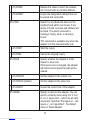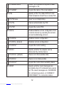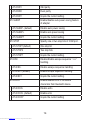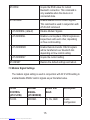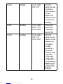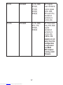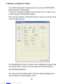
1
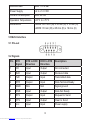
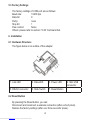
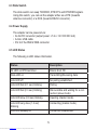
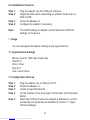
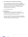
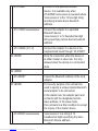
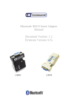
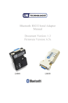
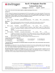
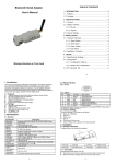
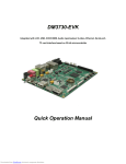
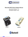
Bluetooth RS232 Serial Adapter Manual
Document Version: 1.0
Firmware Version: 6.5x
LM048
Downloaded from Elcodis.com electronic components distributor
LM058
Document History
Revision
Date
Name
Description
1.0
25-03-2011
SV
Initial Version
1.1
16-05-2011
PM
Add CE Certs
Downloaded from Elcodis.com electronic components distributor
Table of contents
1. 2. 3. 4. 5. 5.1 5.2
5.3 6. 6.1
6.2 6.3
6.4
6.5
6.6 7. 7.1
7.2 7.3 7.4
7.5 7.6 7.7 7.8 7.9 8. 9. 10.
11.
Introduction Features Package General Specification RS 232 Interface Pin Out Signals
Factory Settings Installation Hardware Structure
Reset Button Slide Switch
Power Supply
LED Status
Installation procedure Usage Hyperterminal Settings
Configuration Start up Master Role Configuration Configure Master-Slave Adapter pair 3 wire configuration 5 wire configuration 7 wire configuration AT Command set Modem Signals Windows configuration software
Warranty, Help and Support
Disposal notice LM048 and LM058 CE Declaration
Downloaded from Elcodis.com electronic components distributor
Page 1
Page 1
Page 2
Page 2
Page 3
Page 3
Page 3
Page 4
Page 4
Page 4
Page 4
Page 5
Page 5
Page 5
Page 6
Page 6
Page 6
Page 6
Page 7
Page 7
Page 7
Page 7
Page 8
Page 8-15
Page 15-17
Page 18
Page 19
Page 20
Page 21-22
1. Introduction
Welcome to the LM Technologies Bluetooth RS232 Serial adapter user
manual. The LM048/LM058 adapter eliminates your conventional RS232
serial cables, providing an easy-to-use, invisible connection with superior
freedom of movement. This adapter allows any device with a standard 9-pin
serial port to communicate wirelessly.
This adapter can use both RTS/CTS flow control or DTR/DSR handshaking.
This adapter is capable emulating a serial cable in true sense by transferring
all the RS232 controls signals (RTS, CTS, DTR and DSR) wirelessly to the
remote side over a bluetooth link. This capability is beneficial in case of
Serial Printers which report error conditions like “Out of Paper”, “Power
failure” etc by de-asserting the DTR or RTS lines.
This adapter is mostly used in pairs as serial cable replacement. However,
you can communicate with another Bluetooth serial adapter or other
Bluetooth enabled devices such as a laptop computer, PDA or mobile
phone.
2. Features
•
•
•
•
•
•
•
•
Supports Bluetooth Serial port profile and Generic Access profile
No need of external host and software
Ease of installation, maintenance and use
Supports configuration of local device
Range up to 100 meters (open space)
Support of RTS/CTS data flow control
Support of DTR/DSR handshaking
Ability to transfer RTS, CTS, DTR and DSR signals wirelessly over
bluetooth link. This unique signal handling feature is used in reporting
messages such as “Out of Paper” or “Off Line” from a Serial Printer back
to the PC or Terminal equipment
• Certified by leading Serial Printer Manufacturers like Casio, Star
Micronics and Casio
• Supports External SMA Antenna (LM058 only)
1
Downloaded from Elcodis.com electronic components distributor
3. Package
•
•
•
•
•
•
Bluetooth serial adapter
DB9 male to female converter
USB cable for power supply
User manual
Warranty Card
2Dbi Antenna (LM058 only)
Optional:
• 9 pin to 25 pin converter
• All in one power supply (UK, EU and US Plug)
4. General Specification
Specification
Description
Baud Rate
1.2/2.4/4.8/9.6/19.2/38.4/57.6/115.2/230.4/460.
8/ 921.6 Kbps
Coverage
Up to 100 Metres
Connection
Point-to-Point (piconet)
Signal
TxD, RxD, GND, RTS, CTS, DTR, DSR
RS-232 Interface
D_SUB 9-pin female
Standard Bluetooth
Specification v2.1+EDR
Frequency
2.400 to 2.4835 GHz
Hopping
1,600/sec, 1MHz channel space
Modulation
GFSK-1 Mbps, DQPSK-2 Mbps,
and 8-DPSK-3 Mbps
Tx. power
Max. 18 dBm (Class 1)
Rx. Sensitivity
-86 dBm typical
Antenna
Chip antenna
2
Downloaded from Elcodis.com electronic components distributor
Antenna Gain
Max. 1 to 2 dBi
Power Supply
+4 to +12 V DC
Current Consumption
Max. 90 mA
Operation Temperature
-20°C to +75°C
Dimensions
LM048: 46.3 mm (W) x 34 mm (D) x 16 mm (H)
LM058: 35 mm (W) x 65 mm (D) x 16 mm (H)
5 RS232 Interface
5.1 Pin-out
5.2 Signals
Pin
DTE
Signal
DTE to DCE
Direction
DCE to DTE
Direction
Description
1
CD
Input
Output
Not connected
2
RxD
Input
Output
Received data
3
TxD
Output
Input
Transmitted data
4
DTR
Output
Input
Data Terminal Ready
5
GND
N/A
N/A
Signal ground
6
DSR
Input
Output
Data Set Ready
7
RTS
Output
Input
Request to Send
8
CTS
Input
Output
Clear to Send
9
Vcc
Input
Input
Power supply
3
Downloaded from Elcodis.com electronic components distributor
5.3 Factory Settings
The factory settings of COM port are as follows:
Baud rate: 19200 bps
Data bit: 8
Parity: none
Stop bit: 1
Flow control: None
Others: please refer to section 7.8 AT Command Set.
6. Installation
6.1 Hardware Structure
The figure below is an outline of the adapter.
1. Link LED
2. Data LED
3. Power LED
5. RS232 connector
6. Slide Switch
7. Reset Button
4. Mini USB
connector
6.2 Reset Button
By pressing the Reset button, you can:
Disconnect and reconnect a wireless connection (after a short press).
Restore the factory settings (after over three seconds’ press).
4
Downloaded from Elcodis.com electronic components distributor
6.3 Slide Switch
The slide switch can swap TXD/RXD, RTS/CTS and DTR/DSR signals.
Using this switch, you can set the adapter either as a DTE (towards
antenna connector) or a DCE (towards RS232 connector).
6.4 Power Supply
The adapter can be powered via:
• An AC/DC converter (output power: +5 to +12 V DC/300 mA)
• A mini- USB cable
• Pin 9 of the RS232 DB9 connector
6.5 LED Status
The following is LED status information.
Status
Description
All LED on/off three times
Device boot OK.
Data LED on
Transmitting/Receiving data.
Link LED off
No pairing established.
Link LED fast (0.1 sec) blinking
Pairing
Link LED fast (0.3 sec) blinking
Discoverable and waiting for a connection (slave mode)
Link LED slow (0.9 sec) blinking
Inquiring (master mode).
Link LED very slow (1.2 sec)
blinking
Connecting (master mode).
Link LED steadily on
Connection established.
5
Downloaded from Elcodis.com electronic components distributor
6.6 Installation Procedure
Step 1: Step 2: Step 3: Step 4:
Plug the adapter into the COM port of device.
Adjust the slide switch, depending on whether the device is a
DCE or DTE.
Power the adapter on.
Configure the adapter if necessary.
Note:
The UART settings on adapter should match the COM Port
settings on the device.
7. Usage
You can reprogram the adapter settings using HyperTerminal.
7.1 HyperTerminal Settings
Bits per second: 19200 bps (baud rate)
Data bit: 8
Parity: None
Stop bit: 1
Flow control: None
7.2 Configuration Start-up
Step 1:
Step 2:
Step 3:
Step 4:
Step 5:
Plug the adapter into a COM port of PC.
Power the adapter on.
Create a HyperTerminal file.
On the interface of the new Hyper Terminal file, click Properties
Button.
Select the COM port where the adapter is attached to your PC
and set the port properties as described in section 7.1 Hyper
Terminal Settings.
6
Downloaded from Elcodis.com electronic components distributor
Step 6:
Step 7:
Input “A” in the file.
If no echo, that is, nothing is displayed when you input “A”, it
indicates that the COM port settings are incorrect or slide switch is
in the wrong position.
Input “AT”, and then press <Enter>. “OK” is displayed.
If necessary, reprogram the configuration of adapter using AT
commands. For related commands, please refer to section 7.8 AT
Command Set.
7.3 Master Role Configuration
You can use “AT+ROLEM” to change the adapter to the master role.
When the adapter is in the master role, you can use “AT+ACON-” to
manually set up a connection and “AT+FIND?” to find the device you
want to connect.
7.4 Configure Master-Slave adapter pair
Please refer to configuration utility software (Section 8) to configure a
master slave adapter pair. Once the configuration is done, the pair will
connect to each other automatically.
7.5 3 wire configuration (Tx, Rx, GND)
The default configuration is the 3 wire configuration in which only Tx,
Rx and GND lines are used. Set the 3 wire configuration by sending
AT+FLOW- and AT+MODEM- command.
7.6 5 wire configuration (Tx, Rx, GND, RTS, CTS)
Set 5 wire configuration which uses RTS, CTS flow control signals by
sending AT+FLOW+ and AT+MODEM- command. RTS, CTS status is not
transferred wirelessly over Bluetooth link to the remote side.
7
Downloaded from Elcodis.com electronic components distributor
7.7 7 wire configuration (Tx, Rx, GND, RTS, CTS, DTR, DSR)
Set 7 wire configuration by sending AT+FLOW+ and AT+MODEMR
command. RTS, CTS lines are used for local flow control between device
and adapter. DTR, DSR lines are used for handshaking between local
device and remote connected device. The DTR, DSR line status is
transmitted wirelessly over bluetooth link
For all settings refer section 7.9
7.8 AT Command Set
The following is the AT command set for the local adapter in the
command mode (that is, the local adapter is in the disconnection state).
All the commands and parameters are case insensitive.
Please note “AT+FIND?” command is available only when the adapter is
in the manual master role. In other words, you should send “AT+ROLEM”,
“AT+ACON-” before sending “AT+FIND? command“
8
Downloaded from Elcodis.com electronic components distributor
Command
Description
+++
Switch the device from online Data mode
to online command mode while
maintaining the connection to the remote
device. The characters should be send
with 1000 ms guard time..
AT
Check the serial UART port settings of the
adapter.
AT+VER
Inquire the current firmware version
AT+ENQ
Lists all the settings along with their brief
description. The settings include serial
port, Bluetooth related and other misc
settings
AT+ACON
Enable/disable auto-connection feature in
master role. Note, it will cause a reboot.
ACON+ (default)
Automatically connect to the adapter
specified in AT+BOND=xxxxxxx. If no
device is specified then connect to any
device which is ready to accept
connection.
ACON-
Disable auto-connection feature.
After it is executed, you need to execute
“AT+CONN” to manually connect a
remote device.
ACON?
Inquire the current setting.
AT+CONN
Establish a connection. It is available only
when the adapter is in the manual master
role.
9
Downloaded from Elcodis.com electronic components distributor
AT+CONN
Connect to the specified bonded
device. It is available only when
AT+BOND=xxxxxxxxxx is executed where
“xxxxxxxxxxxx” is the 12 hex digit string
specifying remote device bluetooth
address.
AT+CONN=xxxxxxxxxxxx
Connect the adapter to a specified
Bluetooth device.
“xxxxxxxxxxxx” is 12 hexadecimal digit
string specifying remote device bluetooth
address.
AT+CONNn (n=1-8)
Connect the adapter to a device in the
neighborhood found through “AT+FIND?”
AT+DROP
Drop the connection when the device is
in either master or slave role. It is only
allowed when the device is in connected
state
AT+ADDR
AT+ADDR?
AT+BOND
AT+BOND=xxxxxxxxxxxx
Downloaded from Elcodis.com electronic components distributor
Inquire the Bluetooth address of the local
adapter.
For security purpose, this command is
used to specify a unique remote Bluetooth
serial adapter to be connected.
In the master role, the adapter pairs and
connects with the designated remote
slave address. In the slave mode,
this command is a filter condition to accept
the inquiry of the master device.
“xxxxxxxxxxxx” is a string of 12
hexadecimal digits specifying the slave
Bluetooth Device address.
10
AT+BOND-
Restore the status in which the adapter
can connect with any remote address.
AT+BOND?
Inquire the designated address that can
be paired and connected.
AT+FIND
Search for any Bluetooth device in the
neighborhood within one minute. If any
device is found, its name and address will
be listed. The search ends with a
message “Inquiry ends. xx device(s)
found.”
This command is available only when the
adapter is in the manual master role.
AT+FIND?
Start the inquiry
AT+FIND-
Cancel the ongoing inquiry
AT+ROLE
Specify whether the adapter is in the
master or slave role.
If the device role is changed, the adapter
will reboot and all paired records will be
cleared.
AT+ROLEM
Set the adapter to the master role.
AT+ROLES (default)
Set the adapter to the slave role.
AT+ROLE?
Inquire the current role of the adapter.
AT+NAME
Specify a name for the adapter. You can
specify a friendly name using 0 to 9, A to
Z, a to z, space and –, which are all valid
characters. Note that “first space or -, last
space or – isn’t permitted”. The default
name is “Serial Adapter”.
11
Downloaded from Elcodis.com electronic components distributor
AT+NAME=xxxxx
“xxxxx” is a character string with a maximal length of 16.
AT+NAME?
Inquire the name of the local adapter.
AT+PIN
Specify a PIN. The default PIN is“1234”.
Paired adapters should have a same PIN.
AT+PIN=xxxx
“xxxx” is a 4-8 digit string.
AT+PIN-
Cancel authentication by PIN.
AT+PIN?
Inquire the current PIN.
AT+RCFG
Enables/disable remote configuration from
a remote device by executing the remote
access handshaking protocol.
AT+RCFG+
Enables remote configuration.
AT+RCFG- (default)
Disables remote configuration.
AT+RCFG?
Inquire the current setting
AT+DCOV
Specify whether the adapter can be
discovered by remote device.
AT+DCOV+ (default)
Device is in discoverable state.
AT+DCOV-
Device is non discoverable.
AT+DCOV?
Inquire the current discoverability status.
AT+RESP
Specify whether result messages are
prompted when AT commands are executed. The result messages are: OK/ERROR
for command execution, or CONNECT/
DISCONNECT for connection status.
12
Downloaded from Elcodis.com electronic components distributor
AT+RESP+ (default)
Prompt result messages.
AT+RESP-
Not prompt result messages.
AT+RESP?
Inquire the current setting.
AT+FLOW
Enables or disables RTS/CTS signals
handshaking of the UART port. Note, the
setting will cause a reboot
AT+FLOW- (default)
Disable RTS/CTS flow control
AT+FLOW+
Enable RTS/CTS flow control
AT+FLOW?
Inquire the current setting
AT+BAUD
Specify the baud rate of COM port.
AT+BAUD10
1200 bps
AT+BAUD11
2400 bps
AT+BAUD12
4800 bps
AT+BAUD13
9600 bps
AT+BAUD14 (default)
19200 bps
AT+BAUD15
38400 bps
AT+BAUD16
57600 bps
AT+BAUD17
115200 bps
AT+BAUD18
230.4 Kbps
AT+BAUD19
460.8 Kbps
AT+BAUD20
921.6 Kbps
AT+BAUD?
Inquire the current baud rate.
AT+PAR
AT+PAR0(default)
Specify parity bit setting of COM port.
None parity bit.
13
Downloaded from Elcodis.com electronic components distributor
AT+PAR1
Odd parity.
AT+PAR2
Even parity
AT+PAR?
Inquire the current setting.
AT+SLEEP
Enable/disable auto-power saving feature
of adapter
AT+SLEEP- (default)
Disable auto power saving
AT+SLEEP+
Enable auto power saving
AT+SLEEP?
Inquire the current setting.
AT+STOP
Specify one or two stop bits of COM port.
AT+STOP1(default)
One stop bit.
AT+STOP2
Two stop bits.
AT+STOP?
Inquire the current setting.
AT+ESC
Disable/Enable escape sequence “+++”
handling.
AT+ESC-
Disable escape sequence handling.
AT+ESC+ (default)
Enable escape sequence handling.
AT+ESC?
Inquire the current setting.
AT+ECHO
Enable/disable echo of command
characters from bluetooth device.
AT+ECHO-
Disable echo
AT+ECHO+ (default)
Enable echo
AT+ECHO?
Inquire the current setting
14
Downloaded from Elcodis.com electronic components distributor
AT+RSSI
Inquire the RSSI value for current
bluetooth connection. This command is
only available when the device is in
connected state.
AT+MODEM
Enable/disable RS232 modem signals.
This command is used in conjunction with
AT+FLOW command
AT+MODEM- (default)
Disable Modem Signals
AT+MODEML
Enable Local loopback. RS232 signals are
looped back with each other, depending
on flow control setting
AT+MODEMR
Enable Remote transfer. RS232 signals
will be transferred over bluetooth link
depending on flow control setting
AT+MODEM?
Inquire the current setting
AT+RESET
Restore the default settings and reboot.
7.9 Modem Signal Settings
The modem signal setting is used in conjunction with AT+FLOW setting to
enable/disable RS232 control signals as per the table below.
FLOW
CONTROL
(AT+FLOW)
MODEM
SIGNAL
(AT+MODEM)
RS232 SIGNALS
Description
FLOW-
MODEM-
Tx, Rx, GND
3 wire
configuration
15
Downloaded from Elcodis.com electronic components distributor
FLOW+
MODEM-
Tx, Rx, GND,
RTS, CTS
RTS CTS
signals are used
for data flow
control between
host and
adapter, and
NOT transferred
to remote side
wirelessly.
FLOW-
MODEML
Tx, Rx, GND,
RTS<->CTS,
DTR<->DSR
RTS looped
back to CTS,
DTR looped
back to DSR
FLOW+
MODEML
Tx, Rx, GND,
RTS, CTS,
DTR<->DSR
RTS CTS
signals used for
data flow control
between host
and adapter,
and NOT
transferred to
remote side
wirelessly. DTR
looped back
to DSR. This
configuration
is equivalent to
LM048 adapter
running v4.5x
firmware.
16
Downloaded from Elcodis.com electronic components distributor
FLOW-
MODEMR
Tx, Rx, GND,
RTS(R),
CTS(R),
DTR(R),
DSR(R)
All 7 signals
used. All RS232
control signals
(DTR, DSR,
RTS and CTS)
transferred
wirelessly to
remote side.
FLOW+
MODEMR
Tx, Rx, GND,
RTS, CTS,
DTR(R),
DSR(R)
All 7 lines used.
Only DTR, DSR
signals
transferred
wirelessly to
remote side.
If RTS, CTS
signals are not
used, then this
configuration
is equivalent
to LM048
SPA Adapter
running v4.6X
firmware.
17
Downloaded from Elcodis.com electronic components distributor
8. Windows configuration software
The LM149 Configuration Software allows easy setup of LM048/LM058
RS232 Bluetooth serial adapters.
To start the configuration software click “Get Device Info” in order to view
current settings of LM048/LM058 adapter.
Once you have setup the configuration that you require you will then need
to click “program Device”.
The LM048/LM058 can also be paired via the configuration program using
the “Pairing” button. It takes you to the page which provides option for
Pairing/Unpairing adapters.
If you want to set the adapter back to the factory default settings please
click the “Restore Factory Settings” button.
18
Downloaded from Elcodis.com electronic components distributor
9. Warranty, Help and Support
One (1) Year International warranty
Your LM Technologies LM048/LM058 is warranted by your supplier
for a period of one (1) year from the original date of purchase, under
the terms and conditions of this warranty. This warranty covers
materials and manufacturing defects. Your supplier will require
proof of purchase before replacing the defective product. Registration is
mandatory to access the help system within the LM Technologies website.
Help is available through this document, the user manual within the LM149
configuration software and our website.
This document and other documentation including the most up to date
frequently asked questions (FAQ) and troubleshooting solutions are
available from the support page of the LM Technologies website.
You may need to install a version of acrobat reader which is free to
download to access this material.
Please use the enclosed warranty card or register by visiting our website
and completing the registration form online
19
Downloaded from Elcodis.com electronic components distributor
10. Disposal Notice
DISPOSAL OF OLD ELECTRICAL AND ELECTRONIC EQUIPMENT
The symbol indicates that this product shall not be mixed with unsorted
municipal waste when disposed of. There is separate collection system for
waste electrical and electronic equipment.
Usually old electrical and electronic equipment can be returned free of
charge.
For further information please contact the competent municipal authorities
or shop where you purchased the product. Correct disposal ensures that
waste electrical and electronic Equipment is recycled and reused
appropriately. It helps avoid potential damage for the environment and
human health and to preserve natural resources.
20
Downloaded from Elcodis.com electronic components distributor
EU Declaration of Conformity (RTTE)
LM Technologies, 26 D Guosheng Tai, Guozhan block, Buji Town,
Shenzhen, China.
(Factory name, address)
Declare under our sole responsibility that the product
Bluetooth RS232 Adapter (LM048)
To which this declaration relates is in conformity with
RTTE Directive 1999/5/EC ( Annex II )
Low Voltage Directive 73/23/EEC:93/68/EEC
EMC Directive 89/336/EEC:92/31/EEC
By application of the following standards
EN 300 328
November 2004
V1.6.1
EN 301 489-1
August 2002
V1.4.1
EN 301 489-17
August 2003
V1.2.1
EN 609 950-1
2001
EN 50371
14 June 2002
.........................................................................................
.........................................................................................
.........................................................................................
.........................................................................................
.........................................................................................
(Manufacturer)
LM Technologies,
26D Guosheng tai,
Guozhan block,
Buji Town, Shenzhen,
China.
08/01/2008
...........................................
Mr Lee Parry / Director
....... ................................................................................
(Place and date of issue)
(name and signature of authorized person)
(Representative in the EU)
LM Technologies Ltd
Unit 10, Caroline Point,
62 Caroline Street,
Birmingham, B3 1 UF.
UK
08/01/2008
.............................................
(placeanddateofissue)
Mr Lee Parry / Director
.... ...............................................................................
(nameandsignatureofauthorizedperson)
21
Downloaded from Elcodis.com electronic components distributor
EU Declaration of Conformity (RTTE)
LM Technologies, 26 D Guosheng Tai, Guozhan block, Buji Town,
Shenzhen, China.
(Factory name, address)
Declare under our sole responsibility that the product
Bluetooth RS232 Adapter (LM058)
To which this declaration relates is in conformity with
Low Voltage Directive 73/23/EEC:93/68/EEC
EMC Directive 89/336/EEC:92/31/EEC
By application of the following standards
EN 300 328
November 2004
V1.6.1
EN 301 489-1
August 2002
V1.4.1
EN 301 489-17
August 2003
V1.2.1
EN 609 950-1
2001
EN 50371
14 June 2002
.........................................................................................
.........................................................................................
.........................................................................................
.........................................................................................
.........................................................................................
(Manufacturer)
LM Technologies,
26D Guosheng tai,
Guozhan block,
Buji Town, Shenzhen,
China.
08/01/2008
...........................................
Mr Lee Parry / Director
....... ................................................................................
(Place and date of issue)
(name and signature of authorized person)
(Representative in the EU)
LM Technologies Ltd
Unit 10, Caroline Point,
62 Caroline Street,
Birmingham,
B3 1UF. UK
08/01/2008
.............................................
(placeanddateofissue)
Mr Lee Parry / Director
.... ...............................................................................
(nameandsignatureofauthorizedperson)
22
Downloaded from Elcodis.com electronic components distributor
Copyright © LM Technologies Ltd - 2011
Downloaded from Elcodis.com electronic components distributor