1
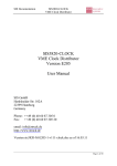
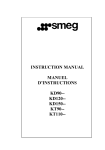
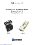
User’s Manual, V 1.0, June 2003
Motor Control
Development Kit
A reference design for low voltage 3-phase AC
induction and brushless DC motor control.
Microcontrollers
N e v e r
Downloaded from Elcodis.com electronic components distributor
s t o p
t h i n k i n g .
Motor Control Development Kit
Revision History:2003-06 V 1.0
Previous Version:Page
1.0
Subjects (major changes since last revision)
June 2003: First Release
References
Infineon C868 User’s Manual
http://www.infineon.com/cmc_upload/documents/048/247/
UM_c868_BA_singlepage_v1.0.pdf
Infineon TLE6280GP Datasheet
http://www.infineon.com/cmc_upload/documents/014/220/TLE6280GP_P6_1.pdf
We Listen to Your Comments
Any information within this document that you feel is wrong, unclear or missing at all?
Your feedback will help us to continuously improve the quality of this document.
Please send your proposal (including a reference to this document) to:
[email protected]
Downloaded from Elcodis.com electronic components distributor
Motor Control Development Kit
Introduction
1
Introduction
This user manual describes the MCDK, Motor Control Development Kit reference design
board and its functions.
The MCDK reference design provides a turnkey solution for driving 3-phase low voltage
brushless DC and AC induction motors, which are usually powered by batteries. The
hardware design applies a broad range of Infineon IC products including microcontroller,
bridge driver, power transistor, temperature sensor and voltage regulator. Infineon also
makes Hall Effect sensors which often are placed inside Brushless DC motors for
position sensing. Also included in the kit is reference software. This reference solution
allows engineers to shorten the development cycle, reduce the design cost and cut the
time from concept to market significantly.
The reference software provided with the MCDK release demonstrates a variable speed
drive for a high speed brushless DC motor with hall sensors, the motor has the following
features:
•
•
•
•
24V DC Supply
3-phase, 4-pole, trapezoidal
¾ Horse Power
Speed up to 30,000 RPM
The software can be trivially changed to adopt different type of 3-phase brushless DC
motors.
User’s Manual
Downloaded from Elcodis.com electronic components distributor
3
V 1.0, 2003-06
Motor Control Development Kit
MCDK Overview
2
MCDK Overview
2.1
Parameters
The MCDK reference design meets the following specifications:
Low Voltage: 12V ~ 24V DC
High Current: 50A, continuous DC
Output Power: Up to 1.2KW
Power Efficiency: > 95%
2.2
Features
• 8-bit MCU: C868 with on-chip 8kB SRAM, 5 channel 8-bit ADC and powerful PWM
module CAPCOM6E
• 3-Phase Bridge Driver: TLE6280G
• 6 OptiMOS MOSFETs: SPB80N06S2-05, TO263 package, 55V / 80A / 4.8 mΩ
RDS(on)
• EEPROM: 8kB to store program + stand alone boot option
• RS232: Interface to PC for SW development + boot from PC option
• Protection: shut down protection for over current and over temperature
• Board can be used for current/torque or speed control
• Supports Hall-Effect sensors or sensor-less control
• Extension for alternative MCU like XC164
• Small foot print: 5¼” x 3” dimension (133.4mm x 76.2mm)
• SW development tools: Keil Compiler + Debugger or Mini Debugger
http://www.keil.com + free reference software
User’s Manual
Downloaded from Elcodis.com electronic components distributor
4
V 1.0, 2003-06
Motor Control Development Kit
MCDK Overview
2.3
Assembly
Power Transistors
Current Sensor
Bridge
Driver
Motor
Wires
DC
Supply
Hall Signals
Pot for
speed
setting
EEPROM
Expansion I/Os for Alternate MCU
C868 MCU
RS232
Figure 1
Assembly of the MCDK Board
User’s Manual
Downloaded from Elcodis.com electronic components distributor
5
V 1.0, 2003-06
Motor Control Development Kit
Hardware Design
3
Hardware Design
The hardware is designed with maximum versatility and flexibility to meet fluctuating
motor drive needs:
•
•
•
•
•
•
CPU selections between C868 and alternatives like C164, XC164 and TriCore.
Power Transistor Packages compatible in both DPAK and D2PAK
Bridge Driver selection between TLE6280 or TLE6287
Motor rotor position detection through hall sensors or sensor-less calculation.
Booting sequences via EEPROM, RS232 or on-chip ROM.
Circuit protections for over current and over temperature conditions
The following block diagram illustrates the basic idea to drive a 3-phase AC induction or
BLDC motor.
Intelligence
C868
Bridge driver
Power Stage
VD
Position Feedback: Sensor or Sensor-less
Figure 2
Block Diagram of 3-phase Motor Control Circuit
The Infineon C868 microcontroller implements a powerful PWM unit CAPCOM6E, which
is able to generate optimized PWM waveform for all kind of motor controls with minimal
CPU load.
The following diagram illustrates how the CAPCOM6E can generate 6-channels of PWM
signals according to the 3 hall sensor position signals, to drive a 3-phase BLDC motor.
The CAPCOM6E is very flexible and can generate practically any pattern that is desired.
User’s Manual
Downloaded from Elcodis.com electronic components distributor
6
V 1.0, 2003-06
Motor Control Development Kit
Hardware Design
Period Reg. CT1P
Mod
Offset Reg. CT1OF
Input
FCP Control
Compare Timer
Timer 16-bit
16-bit
Compare
Compare
Co
Timer
Input
Control
Speed 0 CC0
CC Channel
Port
CC0
COUT0
CCPhase
Channel
1 CC1
Delay*
Control
CC1
COUT1
Time
(Stall2Detect)
CC Out
Channel
CC2
Hall
Effect*
deadtime
Noise
Filter
Control
FCP
CTRAP
PWM
Signals
CC2
COUT2
Burst Mode
Comp Reg. CMP2
Block
Commutation
Control
Period Reg.
COUT3
INT0
INT1
INT2
Hall Pattern
Signals
Figure 3
Block Diagram of the CAPCOM6E PWM Unit (with C868)
User’s Manual
Downloaded from Elcodis.com electronic components distributor
7
V 1.0, 2003-06
Motor Control Development Kit
Board Configurations
4
Board Configurations
The MCDK board is pre-configured during production. The following table shows the
factory setting for circuit breaks and jumpers:
–
–
–
–
–
–
–
–
–
–
–
–
–
CB1: Close
CB2: Close
CB3: Open
CB4: Open
CB5: Close
CB6: Open
JP1: 1+2
JP2: 2+3
JP3: Close
JP4: 1+2
JP5: 1+2
JP6: 1+2
JP7: 1+2
4.1
Circuit Break Settings
The circuit breaks are pre-set in the assembly process, a solder drop between the gap
makes the circuit break ‘Close’, otherwise the circuit break is ‘Open’.
The circuit breaks CB4, CB5 and CB6 are used to select two types of Infineon bridge
drivers, the factory setting is choosing the TLE6280. To choose the TLE6287, the
configuration for CB4, CB5 and CB6 will be:
Table 1
TLE6287
Configurations for using TLE6287 bridge driver
CB4
CB5
CB6
Close
Open
Close
The circuit breaks CB1 and CB2 make the board flexible for users who want to use the
A/D ports of the microcontroller for alternate purpose. In this case, they need to be
‘Open’. While CB3 is closed, the board can supply a DC voltage to the external RS232
connections where opto-isolation can be applied.
User’s Manual
Downloaded from Elcodis.com electronic components distributor
8
V 1.0, 2003-06
Motor Control Development Kit
Board Configurations
4.2
Jumper Settings
Jumper setting is more flexible, users can change “on-the-fly” to meet specific
applications.
Table 2
Jumper setting for bootstrap mode
JP1: Bootstrap Mode Selection
1-2
Bootstrap Mode
2-3
Normal ModeTable
Table 3
Jumper setting for logic power supply voltage
JP2: Logical Power Supply Voltage Selection
1–2
Vcc = + 5V
2–3
Vcc = + 3.3V
Table 4
Jumper setting for boot enable and disable
JP3: Boot Enable/Disable
Open
Boot from PC via RS232
Close
Boot from EEPROM
Table 5
Jumper setting for position detection methods
JP4, JP5 and JP6: Position Detection
1-2
Hall Sensor
2-3
Sensor-less
Table 6
Jumper setting for A2D input selection
JP7: A/D Input selection
1-2
Temperature Input
2-3
Current Input
User’s Manual
Downloaded from Elcodis.com electronic components distributor
9
V 1.0, 2003-06
Motor Control Development Kit
Get Started
5
Get Started
5.1
Run the Demo
The EEPROM on the board has been pre-programmed with a BLDC motor control
reference demo, the microcontroller C868 will boot from the EEPROM and automatically
fetch then execute the code after power-up. The potentiometer for speed setting is
preset at zero RPM.
To run the demo, follow these steps:
• Hook up the motor wires and hall sensor signals of the brushless DC motor to the
board.
• Connect a 12~24V battery with at least 1A output current to the board, the board is
powered up then.
• Turn on the knob of the potentiometer, the motor will starts to spin.
Since the reference code is designed for a demo motor, the code has to be fine tuned
for the right type of motor applied.
5.2
Re-program the EEPROM
Users can re-program the EEPROM with their own code, to do this, follow these steps:
•
•
•
•
•
•
Switch off the power supply by disconnecting the battery.
Open the jumper JP3.
Connect a RS232 cable to the host PC, and execute the Loader program on the PC.
Connect the battery back so the board will be powered up again.
Close the jumper JP3.
Download your code into the EEPROM.
User’s Manual
Downloaded from Elcodis.com electronic components distributor
10
V 1.0, 2003-06
Motor Control Development Kit
Utilize an Alternative Microcontroller
6
Utilize an Alternative Microcontroller
The expansion I/O connector, JP9, allows users to apply an alternative microcontroller
to drive the motor, for example, the Infineon C166 series microcontrollers with integrated
CAPCOM6(E) PWM units such as the XC164.
The signals of the expansion I/O JP9 are described in the following table:
Table 7
Description of Expansion I/Os of JP9
Pin # Name
Description
1
CC0
First phase high side PWM signal
2
COUT0
First phase low side PWM signal
3
CC1
Second phase high side PWM signal
4
COUT1
Second phase low side PWM signal
5
CC2
Third phase high side PWM signal
6
COUT2
Third phase low side PWM signal
7
CTRAP
Over current trap signal
8
POS0
Rotor position signal
9
POS1
Rotor position signal
10
POS2
Rotor position signal
11
Temp/
Current
Temperature or Current amplitude
12
SPEED
Motor speed setting
13
MFP
Multifunction control signal for bridge drive
14
ERR
Error signal from bridge drive
15
TX
Transmitting signal of RS232
16
RX
Receiving signal of RS232
17
CS
Chip select signal for EEPROM
18
SIO
Serial I/O pin of EEPROM
19
SCK
Serial Clock signal of EEPROM
20
GND
Ground
21
RST
Reset signal for CPU
22
+3.3V
Logic voltage supply when C868 used
23
+5V
Logic voltage supply when alternate MCU used, i.e., C164xx
24
GND
Ground
25
+24V_IN
DC power supply (filtered)
User’s Manual
Downloaded from Elcodis.com electronic components distributor
11
V 1.0, 2003-06
Motor Control Development Kit
Utilize an Alternative Microcontroller
The expansion I/Os provide all the necessary signals for external microcontroller to
access the EEPROM, RS232 interface and motor drive circuits. There are two ways to
utilize an alternate microcontroller: One is to design a mezzanine board that can plug on
top of the MCDK board through the JP9 connector, the other way is to connect a 25pin
flat cable to an existing microcontroller board (e.g., a starter kit). For the MCDK board,
some changes have to be done: the on-board C868 device must be un-populated to
avoid signal conflicts, also the jumper JP2 should be re-positioned if the alternate
microcontroller uses a different I/O logic voltage supply, i.e., +5V.
User’s Manual
Downloaded from Elcodis.com electronic components distributor
12
V 1.0, 2003-06
Motor Control Development Kit
Appendix 1: Layout
7
Appendix 1: Layout
Figure 4
Assembly Bottom
Figure 5
Assembly Top
User’s Manual
Downloaded from Elcodis.com electronic components distributor
13
V 1.0, 2003-06
Motor Control Development Kit
Appendix 1: Layout
Figure 6
Bottom
Figure 7
Top
User’s Manual
Downloaded from Elcodis.com electronic components distributor
14
V 1.0, 2003-06
Motor Control Development Kit
Appendix 1: Layout
Figure 8
Mask bottom
Figure 9
Mask top
User’s Manual
Downloaded from Elcodis.com electronic components distributor
15
V 1.0, 2003-06
Motor Control Development Kit
Appendix 1: Layout
Figure 10
Silk Bottom
Figure 11
Silk Top
User’s Manual
Downloaded from Elcodis.com electronic components distributor
16
V 1.0, 2003-06
Motor Control Development Kit
Appendix 2: BOM
8
Appendix 2: BOM
Table 8
Bill of Material for MCDK Reference Design
Designator
Quantity Part Type
Footprint
CB1->CB6
6
Solder drop
custom footprint
C1->C3
3
2.2F
_0805
C4->C6
3
0.22µF
_0805
C7
1
15uF / 25V
D-PACK
C8, C19
2
1µF
_1206
C9
1
12nF
_0805
C10, C11
2
10µF-100v
Radial/Bulk
C16
1
10nF
_0603
C17, C18
2
22pF
_0603
C20, C21, C23, C25, C26,
C27, C29, C31, C32, C33,
C35, C36
12
100nF
_0603
C22, C24
2
10µF
_1206
C28
1
10nF
_0603
D1
1
1N4148
SOD-123
D2
1
1201:red/
orang,
1202:red
_1206
D3
1
404-1059-1- _1206
ND
JP1,JP2,JP4->JP7
6
HEADER 3
SIL3
JP3
1
JUMPER
SIL2
JP9
1
HEADER 25 SIL25
JP10
1
HEADER 2
J1
1
Motor Wires Conn Hdr Vert Mini Fit SR 3Pos
J2
1
Hall Sensor
Signals
SIL5
J3
1
DC Power
Supply
Conn Hdr Vert Mini Fit SR 2Pos
User’s Manual
Downloaded from Elcodis.com electronic components distributor
17
SIL2
V 1.0, 2003-06
Motor Control Development Kit
Appendix 2: BOM
Table 8
Bill of Material for MCDK Reference Design
Designator
Quantity Part Type
Footprint
M1->M6
6
SPB80N06
S2-05
P- TO263 -7-3
OZ1
1
CSTLA10M SIL3
6T55002-B0
PB1
1
P8075SCTND
POT1
1
ST7A103CT 7mm Squared SMD J-Lead-CT
-ND
POT2
1
3310C-1103-ND
9mm Squared RT ANGLE PLAS
P1 - MALE
1
A2096-ND
DB9-PCB
R1->R6
6
22Ω
Axial 1/4W type ERDS2T
R13->R18, R27, R33, R34
9
1KΩ
_0603
R19, R31
2
27Ω
_0603
R20
1
22KΩ
_0603
R21
1
47KΩ
_0603
R22
1
300KΩ
_0603
R24
1
20KΩ
_0603
R25, R26, R32, R36
4
10KΩ
_0603
R28
1
10Ω-1.0W
_2512
R29
1
100Ω
_0603
R30
1
270Ω
_0603
R35
1
3KΩ
_0603
R37
1
1KΩ
_0603
R38, R39
2
150Ω
_0603
R40
2
0.005Ω
resistors in parallel, 0.010
ohms@5W
R41
1
4K7Ω
_0603
TP1
1
GND POINT SIL1
T1
1
KT110
SIL2
U1
1
C868TSSOP
tssop38
User’s Manual
Downloaded from Elcodis.com electronic components distributor
18
SPST
V 1.0, 2003-06
Motor Control Development Kit
Appendix 2: BOM
Table 8
Bill of Material for MCDK Reference Design
Designator
Quantity Part Type
Footprint
U2
1
EEPROM
64K 2.7V
SOIC8
U3
1
TLE4274GS P-SOT223-4-1
V33
U4
1
LM6132AIM SOIC8
-ND
U5
1
TLE6280GP P-DSO36-12
U6
1
MAX3221E
User’s Manual
Downloaded from Elcodis.com electronic components distributor
19
TSSOP16
V 1.0, 2003-06
Motor Control Development Kit
Appendix 3: Schematics
9
Appendix 3: Schematics
User’s Manual
Downloaded from Elcodis.com electronic components distributor
20
V 1.0, 2003-06
Motor Control Development Kit
Appendix 4: Waveforms
10
Appendix 4: Waveforms
Phase A
POS0 (H0)
POS1 (H1)
POS2 (H2)
CC0 (A+)
COUT0 (A-)
CC1 (B+)
COUT1 (B-)
CC2 (C+)
COUT2 (C-)
Figure 12
Waveforms of PWM and Hall Pattern Signals Driving a 3-phase BLDC
motor (Measured with a Mixed Signal Oscilloscope).
User’s Manual
Downloaded from Elcodis.com electronic components distributor
21
V 1.0, 2003-06
http://www.infineon.com
Published by Infineon Technologies AG
Downloaded from Elcodis.com electronic components distributor