1
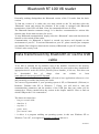
RT100V8.
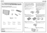
Battery charge level
Display OLED
128×64 pixels
In/out button (1)
LED blue Bluetooth activated
LED red charging battery
LED green battery charged
Mini USB
interface
Scroll up button (2)
Mid button (4)
( Enter)
Scroll down button (3)
ISO FDXB tag
26/02/2013
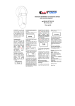
Reader characteristics
Frequency
134.2kHz Read and write ISO 14223
Protocol
ISO11784/5 FDX-A, FDX-B, EM4102, HDX
Reading range
≥8 cm(12mm×2mm, glass tag)
Display
128×64,black and white,OLED
Keys
4
Indication
Battery charge control and Bluetooth . Buzzer
USB port
USB virtual comport,bluetooth virtual com.port
Power supply
Lithium battery,1400mAh,3.7V
Dimension
155mm (L)×82(W)×33(H)
Net weight
155g
Charging mode
Mini USB
Accessories
Mini USB cable, Product instructions. Battery.
Compliance certifications
FCC、CE certification
Memory
Up to 1000 ID numbers
buttons
26/02/2013
Bluetooth RT 100 V8 reader
Externally, nothing distinguishes the Bluetooth version of the V8 reader from the basic
version.
To find the version of a reader, the user must switch on the V8 and then select the
“Bluetooth” menu and activate the function. If the reader is equipped with Bluetooth
transmission, a blue LED will flash. If not, the command will have no effect.
The Bluetooth function consumes energy. It is therefore recommended to activate this
function only for the time necessary for its use.
To stop Bluetooth communication, simply select the “Bluetooth” menu and deactivate the
function or else switch off the reader.
Communication via Bluetooth is limited to around ten metres and depends on the
environment of your PC. To activate Bluetooth on your PC, please consult your computer
user manual. Don’t forget to deactivate the security of Bluetooth on your PC because the
V8 don’t ask a security code.
Data transmission by Bluetooth or via the USB
cable
To be able to transmit the tag numbers read or the numbers recorded in the memory
(maximum 1200), via Bluetooth or using the USB cable, the user needs to have installed the
appropriate driver* on his PC (Pl2303_Prolific_Driver Installer_v1210.exe). This driver can
be
downloaded
free
of
charge
from
our
website
or
from
www.4shared.com/zip/wpeAz3PT/file.html
Once the driver is installed on your PC you will need to have application software to view
and potentially record the data sent by the reader.
You can use Hyperterminal if your operating system is XP, or Datatransfer (Felixcan) or
Realtrace Terminal with XP or Windows 7. Firstly, you will need to enter the
communication parameters and the number of the USB port that your reader will be
connected to. Please consult below the section in the chapter entitled: “How to find out
which USB port the V8 is connected to”.
The data to be entered are:
- bits per second: 9600
- data bits: 8
- stop bits: 1
- parity: none
- flow control: none
* A driver is a program enabling an operating system, in this case Windows XP or
Windows 7 on a PC, to recognise a hardware peripheral and use it.
26/02/2013
System « WOOSIT »
Writing the animal owner’s telephone number(s) in the ISO tag
Our wish to constantly innovate and improve our products has led us to offer vets the option of
personalising the tag, if they wish, before implanting it in the animal.
The main technological advance offered by this V8 reader is that it will allow reading and display of
data which can be entered by the vet in the majority of the “tags” currently marketed worldwide,
provided that they comply with the ISO standard.
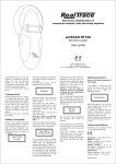
Realtrace has developed a system called “WOOSIT ®” which is comprised of:
- A reader /programmer the PetSCAN RT150 (1) which enables the vet to write additional
information to the “chip” before injecting it into the animal (2).
- The PetSCAN V8 which now offers the possibility to read and display the ID number but also
to display additional data recorded by the vet in the memory as the phone number of the owner.
Due to the low memory capacity available in ISO chips (used up until then) the “WOOSIT” system
is limited to the recording of one or two telephone numbers of 16 digits each . The vet and/or the
owner of the animal may choose these numbers.
This system is totally compliant with the ISO 11784/85 standard of 1996 in addition to the new 14223
standard* (May 2011) concerning the recording of data in advanced transponders.
It protects the asepsis of the chip, as the writing of the data is carried out via the cap which protects
the needle.
If the owner prefers this, after the recording of one or two telephone numbers, the memory area used
for this record can be blocked, making it impossible to delete or subsequently modify this
information.
With the “WOOSIT” system, finding the owner of an animal will be particularly easy as reading the
“chip” with the V8 will provide the phone number(s) of the administrator of the database and/or
the owner of the pet.
Naturally, any pet owner who does not wish to use this service can simply enter nothing in the
memory area of the chip, as is currently the case.
.
ID number and phones numbers
(1)Patented
(2)sous réserve que les blocks 3/9/10/11/12/13 (EM4305) ou 9/10/11/12/13/14/15 (EM 4569) ne soient pas
verrouillés par le fournisseur de la « puce ».
*L'ISO 14223-1:2011 spécifie l'interface hertzienne entre l'émetteur-récepteur et le transpondeur évolué utilisé
pour l'identification des animaux par radiofréquence, à compatibilité ascendante totale avec les spécifications
données dans l'ISO 11784 et l'ISO 11785.
26/02/2013
Synoptic Menu SCAN
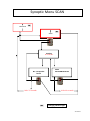
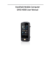
Synoptic Menu “SCAN”
Bluetooth
SCAN
SCAN
Reading
20 seconds max.
No transponder
found!
After 25 seconds
FDXB
939 2784879521125
After 60 seconds
Charging indicator light
26/02/2013
Synoptic Menu “Language”
SCAN
Memory
Language
English
Français
Español
English OK
5 seconds
Français OK
5 seconds
Español OK
5 seconds
Italiano
Italiano OK
5 seconds
Portugues
Portugues OK
5 seconds
Deutsch
Polish
Deutsch OK
5 seconds
Polish OK
5 seconds
26/02/2013
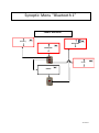
Synoptic Menu “Bluetooth 1”
Enable Bluetooth
Memory
Bluetooth
Bluetooth
SCAN
Enable
26/02/2013
Synoptic Menu « Bluetooth 2 »
Disable Bluetooth
Bluetooth
Bluetooth
Memory
SCAN
Disable
Charging indicator light
Bluetooth indicator light
26/02/2013
Reader “Memory” function
The V8 reader has a memory enabling it to store 1200 identifiers (tag numbers).
This function must be activated by the user if he wishes to use it.
Storage of numbers read by the V8 reader
The V8 allows the user to store the numbers of the tags read in order to transfer them
subsequently to a PC using the USB cable included with the reader.
To use this function, you must first activate the “Memory” function (see block diagram:
“Memory 1”).
Each time a new tag is read, the reader displays the number but if the same tag is read twice by
mistake the reader indicates this by emitting a characteristic beep and displaying “DUP” on the
right of the screen.
This number will not be stored a second time.
If the reader is switched off, the memory function will still be activated when it is switched on
again.
Deactivating the memory
The memory can be deactivated via the “Memory” menu.
Two cases may arise:
First case:
- Numbers are recorded in the reader’s memory (Block diagram: Memory 3)
In this case you must transmit the list of recorded numbers actually or virtually (without
plugging in the USB cable) and then erase them (see Block Diagram: Memory 2)
Second case:
The memory has been previously activated but no number has been recorded.
In this case simply “deactivate” the memory (block diagram: “Memory 2”
Erasing the memory
To erase the contents of the memory to avoid errors, you must select the “Memory” menu and
transmit the list of recorded numbers actually or virtually (without plugging in the USB cable)
and then erase them (see Block Diagram: Memory 3).
26/02/2013
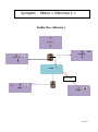
Synoptic Menu « Memory 1 »
Enable the « Memory »
Memory
Language
Bluetooth
Enable
5 secondes
M:0
SCAN
SCAN
26/02/2013
Synoptic Menu « Memory 2 »
Disable the “Memory”
Memory is enable but there is no registration of ID numbers
M: 0
Memory
Language
Bluetooth
Disable
M: 0
SCAN
5 secondes
SCAN
26/02/2013
Synoptic Menu « Memory 3 »
Memory « Enable » but there are datas registered
M: X
Memory
Language
Bluetooth
Send
Press “OK” to Erase
8 seconds
Sending
…………………
5 seconds
………….
8 seconds
Press “OK” to confirm
erase
Erasing
……………………
SCAN
8 seconds
8 seconds
26/02/2013
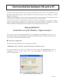
Communication between V8 and a PC
To transfer the contents of the memory you must connect the reader to a PC via the USB cable. You
must then select the “Memory” menu and follow the instructions given on the display (see Block
Diagram: “Memory3”).
If the reader is connected to a PC it will transfer the number of the tag read on each reading. It is not
necessary for the “Memory” function to be activated to carry out this transfer.
Caution: for the reader to communicate with a PC, you must first install the driver and have software
such as Hyperterminal (Windows XP), Datatransfer (Felixcan), Realtrace Terminal, etc. which
enables the data to be displayed on the computer screen and processed if necessary.
PetScan RT100 V8
Serial link: use of the Windows « Hyperterminal »
The current version of the PetScan RT100 V8, transmits the read identifiers to the PC it is
connected to, either via the USB cable or its wireless link (Bluetooth). The PetScan does not wait
for any order or acknowledgement from the PC.
Hardware configuration
The serial port for reading the data is configured as follows:
- 9600 bauds, 8 bits, 1 start bit, 1 stop bit, non-parity, and no flow control.
You must authorize line feeds to visualize the frames using the hyperterminal: click on
« properties » in the « file » menu. Go to the « parameters » and then click on
«
ASCII Configuration… » :
The circled box above must be ticked…
26/02/2013
Description of the frame transmitted each time a transponder is read
The PetScan transmits the following frame to the PC after each valid reading :
Octet at the start of
the
frame : ″U″ ″/x55″
Type of 8
character
(or octet)
chip
The
16
character
(or octet)
chip
identifier
Separation
of
octet: ″*″:
CRC-CCITT-control
word, 16 ASCII format
bits on 4 characters
Carriage
Return
octet: ″/x0D″
Data used to calculate the CRC
Tips: the developers of software associated with PetScan must use the head and separation characters to
separate the information transmitted by PetScan, calculate a control word with the data received and compare it
to the word transmitted by the PetScan to validate the information (see appendix for the CRC-CCITT-16 bit
calculation algorithm)
Description of the frames emitted when reading the databases (PetSCAN memory option)
If a PetScan reader has a memory option, when « Press SCAN to send » is displayed, the reader is ready to
transmit the identifiers stored in the memory. The PetScan displays « Sending ! » during transmission and the
reader offers the user the option of deleting the content of its database at the end of the transmission.
Format of the frames transmitted to the PC : the frame which is transmitted on each reading of a transponder is
preceded by a header octet ″/xAA″, its 4 character registration number in the memory and a separation
character ″*″.
Start of
4 character
Separation
Start of
The type
The 16
Separati
frame
registration
octet: ″*″
information
of 8
character
on of
octet : ″/
number
object : ″U″
character
(or octet)
octet: ″*
″/x55″
(or octet)
chip
″:
chip)
identifier)
xAA″
CRC-CCITT-cont
rol
word,
16
ASCII format bits
Carriage
return
octet: ″/x
on 4 characters
Data used to calculate the CRC
Algorithm for calculating aCRC-CCITT-16bit control word
The C ANSI function’s source code enabling a control word to be calculated from a string of characters
terminating with the character ″/x00″ is described below. The JAVA applet on the
« http://www.zorc.breitbandkatze.de/crc.html », website enables you to also calculate the control word.
Previously the fields had to be correctly completed before making the CRC calculation and a check made that
the control word is equal to 0xE5CC or the ″123456789″ character string.
26/02/2013
0D″
/*=======================================================================*/
/* Function that calculates CRC-CCITT 16 bits
/* INPUT:
/*
unsigned char *inbuffer : 8 bits input vector over which CRC checksum is calculated
/*
must termined by 0x00
/* OUTPUT:
/*
unsigned int: 16 bits return of crc_ccitt checksum
/*=======================================================================*/
/* OVERVIEW:
/*
Width = 16 bits
/*
Truncated polynomial = 0x1021
/*
Initial value = 0xFFFF
/*
No XOR is performed on the output CRC
/* DESCRIPTION:
/* Computing a POLY number from the crc equation.
/* Crc s are usually expressed as an polynomial expression such as:
/*
/*
x^16 + x^12 + x^5 + 1
/* CHECK
/*
0xE5CC This is the checksum for the ascii string "123456789"
/* EXAMPLE
/* http://www.zorc.breitbandkatze.de/crc.html
*=======================================================================*/
#define crc_poly 0x1021
// Polynome du CRC-CCITT-16Bits
unsigned int crc_ccitt16 (unsigned char *inbuffer) {
unsigned int crc_checksum = 0xffff;
unsigned char ch;
char i,xor_flag;
while ( *inbuffer!=0)
{
ch = *inbuffer++;
for(i=0; i<8; i++)
{
xor_flag=(crc_checksum & 0x8000)? 1:0;
crc_checksum = crc_checksum << 1;
if (ch & 0x80) crc_checksum++;
if (xor_flag) crc_checksum = crc_checksum ^ crc_poly;
ch = ch << 1;
}
}
for(i=0; i<16; i++)
{
xor_flag=(crc_checksum & 0x8000)? 1:0;
crc_checksum = crc_checksum << 1;
if (xor_flag) crc_checksum = crc_checksum ^ crc_poly;
}
return (crc_checksum);
}
26/02/2013
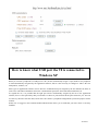
How to know what USB port the V8 is connected to.
Windows XP
When you connect a peripheral to a USB port on a PC, the PC automatically assigns it a port number. The peripheral
is often automatically recognised by the application software, thus it is not necessary to configure it. This is the case
with printers, scanners, etc.
Other types of application software need to have the communication port assigned by the PC indicated to them, in
some cases with other information such as the communication speed, the form of the data transmitted, etc.
As regards the V8, it is possible that the right port will be automatically assigned by the PC to the application
software, but it is also quite likely that you will have to choose it yourself from all the ports offered to you. You can
of course try them one after the other, but in some cases the PC’s peripheral configuration system will propose dozens
of them…
In this case we suggest a more rational method which will also allow you to check that your V8’s driver is correctly
installed.
26/02/2013
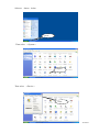
Select as shown below.
Click!
Then select
« System »
Cliquez!
Then select
« Device »
Click!
26/02/2013
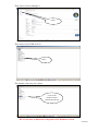
Then Select
« Device Manager »
Cliquez!
Then select
« Ports (com et LPT) »
Click!
The number of the Com port is shown.
Numéro du Port Com
auquel est connecté
le V8
26/02/2013
How to know what USB port the V8 is connected to.
Windows 7
Select as shown below.
Click !
Then select « System »
Click!
26/02/2013
Then select « Device Manager »
Click!
Then select « Port COM et LPT»
Click!
The number of the Com port is shown.
Com3 is the
number of Port
connected to the V8
The screens may be differents. It depends of the Windows version.
26/02/2013