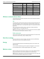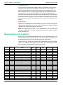
1
EM4300 series wireless energy meter
User manual
7EN02-0356-00
04/2015
Safety information
Important information
Read these instructions carefully and look at the equipment to become familiar
with the device before trying to install, operate, service or maintain it. The
following special messages may appear throughout this bulletin or on the
equipment to warn of potential hazards or to call attention to information that
clarifies or simplifies a procedure.
The addition of either symbol to a “Danger” or “Warning” safety label indicates
that an electrical hazard exists which will result in personal injury if the
instructions are not followed.
This is the safety alert symbol. It is used to alert you to potential personal injury
hazards. Obey all safety messages that follow this symbol to avoid possible
injury or death.
DANGER
DANGER indicates a hazardous situation which, if not avoided, will result in
death or serious injury.
WARNING
WARNING indicates a hazardous situation which, if not avoided, could
result in death or serious injury.
CAUTION
CAUTION indicates a hazardous situation which, if not avoided, could
result in minor or moderate injury.
NOTICE
NOTICE is used to address practices not related to physical injury.
Please note
Electrical equipment should be installed, operated, serviced and maintained only by
qualified personnel. No responsibility is assumed by Schneider Electric for any
consequences arising out of the use of this material.
A qualified person is one who has skills and knowledge related to the construction,
installation, and operation of electrical equipment and has received safety training to
recognize and avoid the hazards involved.
7EN02-0356-00
3
Notices
Legal information
The Schneider Electric brand and any registered trademarks of Schneider Electric
Industries SAS referred to in this guide are the sole property of Schneider Electric SA
and its subsidiaries. They may not be used for any purpose without the owner's
permission, given in writing. This guide and its content are protected, within the
meaning of the French intellectual property code (Code de la propriété intellectuelle
français, referred to hereafter as "the Code"), under the laws of copyright covering
texts, drawings and models, as well as by trademark law. You agree not to reproduce,
other than for your own personal, noncommercial use as defined in the Code, all or part
of this guide on any medium whatsoever without Schneider Electric’s permission, given
in writing. You also agree not to establish any hypertext links to this guide or its content.
Schneider Electric does not grant any right or license for the personal and
noncommercial use of the guide or its content, except for a non-exclusive license to
consult it on an "as is" basis, at your own risk. All other rights are reserved.
Electrical equipment should be installed, operated, serviced and maintained only by
qualified personnel. No responsibility is assumed by Schneider Electric for any
consequences arising out of the use of this material.
As standards, specifications and designs change from time to time, please ask for
confirmation of the information given in this publication.
FCC
This equipment has been tested and found to comply with the limits for a Class B digital
device, pursuant to part 15 of the FCC rules. These limits are designed to provide
reasonable protection against harmful interference in a residential installation. This
equipment generates, uses, and can radiate radio frequency energy and, if not installed
and used in accordance with the instructions, may cause harmful interference to radio
communications. However, there is no guarantee that the interference will not occur in
a particular installation. If this equipment does cause harmful interference to radio or
television reception, which can be determined by turning the equipment off and on, the
user is encouraged to try to correct the interference by one or more of the following
measures:
– Reorient or relocate the receiving antenna.
– Increase the separation between the equipment and receiver.
– Connect the equipment to an outlet on a circuit different from that to which the
receiver is connected.
– Consult the dealer or an experienced radio/TV technician for help.
The user is cautioned that any changes or modifications not expressly approved by
Schneider Electric could void the user’s authority to operate the equipment.
This digital apparatus complies with CAN ICES-3 (B) /NMB-3(B).
This device complies with FCC radiation exposure limits set forth for general
population. This device must be installed to provide a separation distance of at least
20 cm from all persons and must not be co-located or operating in conjunction with any
other antenna or transmitter.
7EN02-0356-00
4
Industry Canada
Under Industry Canada regulations, this radio transmitter may only operate using an
antenna of a type and maximum (or lesser) gain approved for the transmitter by
Industry Canada. To reduce potential radio interference to other users, the antenna
type and its gain should not be so chosen that the equivalent isotropically radiated
power (e.i.r.p) is not more than that necessary for successful communication.
This device complies with Industry Canada license-exempt RSS standard(s). Operation
is subject to the following two conditions: (1) this device may not cause interference,
and (2) this device must accept any interference, including interference that may cause
undesired operation of the device.
This device complies with Industry Canada RF radiation exposure limits set forth for
general population. This device must be installed to provide a separation distance of at
least 20 cm from all persons and must not be co-located or operating in conjunction with
any other antenna or transmitter.
R&TTE
This equipment is in accordance with the requirements of the R&TTE (Radio equipment
and telecommunications terminal equipment) directive for the following authorized
countries:
AT BE BG CH CY CZ DE DK EE ES FI FR GB GR HU IE IS IT LI LT LU LV MT NL PL
PT RO SE SI SK TR BA GE HR MD ME MK RS.
The R&TTE declaration of conformity is available at www.schneider-electric.com.
7EN02-0356-00
5
About this manual
This manual is intended for use by designers, system builders and maintenance
technicians with an understanding of electrical distribution systems, monitoring devices
and wireless technology.
This manual discusses features of the PowerLogic™ EM4300 series wireless energy
meter and provides feature descriptions and configuration instructions. Throughout the
manual, the term “meter” refers to all models of the EM4300 series. All differences
between the models, such as a feature specific to one model, are indicated with the
appropriate model number or description.
Related documents
For more information on EM4300 series devices and wireless energy metering
components and technology, visit the product support download pages at
www.schneider-electric.com and search or browse:
Title of document
7EN02-0356-00
Reference number
EM4300 series installation sheet
NHA1528301
Com’X 200 series user guide
DOCA0036EN
Guidelines for Wireless Energy Metering Deployment in Buildings
(white paper)
—
6
EM4300 series user manual
Contents
Chapter 1
Chapter 2
Safety precautions ................................................................................................... 9
Introduction ............................................................................................................ 11
Meter features . . . . . . . . . . . . . . . . . . . . . . . . . . . . . . . . . . . . . . . . . . . . . . . . . . . . . 11
Measured parameters . . . . . . . . . . . . . . . . . . . . . . . . . . . . . . . . . . . . . . . . . . . . . . . 11
Gateways and data collectors . . . . . . . . . . . . . . . . . . . . . . . . . . . . . . . . . . . . . . . . . 12
Energy data analysis and reporting . . . . . . . . . . . . . . . . . . . . . . . . . . . . . . . . . . . . . 12
Chapter 3
Hardware reference ................................................................................................ 13
Meter details . . . . . . . . . . . . . . . . . . . . . . . . . . . . . . . . . . . . . . . . . . . . . . . . . . . . . . . 13
Physical features . . . . . . . . . . . . . . . . . . . . . . . . . . . . . . . . . . . . . . . . . . . . . . . . . . . 15
Wireless data transfer . . . . . . . . . . . . . . . . . . . . . . . . . . . . . . . . . . . . . . . . . . . . . . . 15
Chapter 4
Installation and commissioning ...........................................................................
Before you begin . . . . . . . . . . . . . . . . . . . . . . . . . . . . . . . . . . . . . . . . . . . . . . . . . . .
Wireless networks . . . . . . . . . . . . . . . . . . . . . . . . . . . . . . . . . . . . . . . . . . . . . . . . . .
Meter mounting and removal . . . . . . . . . . . . . . . . . . . . . . . . . . . . . . . . . . . . . . . . . .
17
17
17
19
DIN rail mounting . . . . . . . . . . . . . . . . . . . . . . . . . . . . . . . . . . . . . . . . . . . . . . . . . . . 19
Flat surface mounting . . . . . . . . . . . . . . . . . . . . . . . . . . . . . . . . . . . . . . . . . . . . . . . . 20
Meter wiring . . . . . . . . . . . . . . . . . . . . . . . . . . . . . . . . . . . . . . . . . . . . . . . . . . . . . . . 20
Control power . . . . . . . . . . . . . . . . . . . . . . . . . . . . . . . . . . . . . . . . . . . . . . . . . . . . . . 20
Current sensors consideration . . . . . . . . . . . . . . . . . . . . . . . . . . . . . . . . . . . . . . . . . 20
Open ZigBee networks consideration . . . . . . . . . . . . . . . . . . . . . . . . . . . . . . . . . . . 21
Power up . . . . . . . . . . . . . . . . . . . . . . . . . . . . . . . . . . . . . . . . . . . . . . . . . . . . . . . . . 21
Scanning mode . . . . . . . . . . . . . . . . . . . . . . . . . . . . . . . . . . . . . . . . . . . . . . . . . . . . 22
Joining mode . . . . . . . . . . . . . . . . . . . . . . . . . . . . . . . . . . . . . . . . . . . . . . . . . . . . . . 22
Binding the meter to the wireless gateway . . . . . . . . . . . . . . . . . . . . . . . . . . . . . . . . 22
Removing the meter from the wireless network . . . . . . . . . . . . . . . . . . . . . . . . . . . . 22
Com’X 200 series energy server and gateway . . . . . . . . . . . . . . . . . . . . . . . . . . . . 22
Com’X 200 series configuration overview . . . . . . . . . . . . . . . . . . . . . . . . . . . . . . . . 23
Verify energy data . . . . . . . . . . . . . . . . . . . . . . . . . . . . . . . . . . . . . . . . . . . . . . . . . . 23
Chapter 5
Measurements and calculations ...........................................................................
Summary of measurements . . . . . . . . . . . . . . . . . . . . . . . . . . . . . . . . . . . . . . . . . . .
Wireless communications status . . . . . . . . . . . . . . . . . . . . . . . . . . . . . . . . . . . . . . .
Real-time readings . . . . . . . . . . . . . . . . . . . . . . . . . . . . . . . . . . . . . . . . . . . . . . . . . .
Energy . . . . . . . . . . . . . . . . . . . . . . . . . . . . . . . . . . . . . . . . . . . . . . . . . . . . . . . . . . .
Min/max values . . . . . . . . . . . . . . . . . . . . . . . . . . . . . . . . . . . . . . . . . . . . . . . . . . . .
Power factor . . . . . . . . . . . . . . . . . . . . . . . . . . . . . . . . . . . . . . . . . . . . . . . . . . . . . . .
Demand . . . . . . . . . . . . . . . . . . . . . . . . . . . . . . . . . . . . . . . . . . . . . . . . . . . . . . . . . .
25
25
26
26
26
26
27
27
Chapter 6
ZigBee Pro implementation ...................................................................................
Measurements and calculations . . . . . . . . . . . . . . . . . . . . . . . . . . . . . . . . . . . . . . . .
Setup and diagnostics . . . . . . . . . . . . . . . . . . . . . . . . . . . . . . . . . . . . . . . . . . . . . . .
Meter identification . . . . . . . . . . . . . . . . . . . . . . . . . . . . . . . . . . . . . . . . . . . . . . . . . .
29
30
32
33
Chapter 7
Maintenance ........................................................................................................... 35
LED troubleshooting . . . . . . . . . . . . . . . . . . . . . . . . . . . . . . . . . . . . . . . . . . . . . . . . . 35
Red LED off, green LED blinks once every 2 seconds . . . . . . . . . . . . . . . . . . . . . . 35
No LED activity . . . . . . . . . . . . . . . . . . . . . . . . . . . . . . . . . . . . . . . . . . . . . . . . . . . . . 35
Red LED behavior . . . . . . . . . . . . . . . . . . . . . . . . . . . . . . . . . . . . . . . . . . . . . . . . . . 36
Red LED turns on for 1 second then off for 1 second . . . . . . . . . . . . . . . . . . . . . . . 36
7EN02-0356-00
7
EM4300 series user manual
Red LED blinks 4 times per second . . . . . . . . . . . . . . . . . . . . . . . . . . . . . . . . . . . . .
Red LED turns on for 1 second then blinks 3 times per second . . . . . . . . . . . . . . .
Red LED stays on . . . . . . . . . . . . . . . . . . . . . . . . . . . . . . . . . . . . . . . . . . . . . . . . . .
Red LED blinks 1 second, turns off 1 second, then blinks 4 times per second . . . .
36
36
37
37
Green LED . . . . . . . . . . . . . . . . . . . . . . . . . . . . . . . . . . . . . . . . . . . . . . . . . . . . . . . . 37
Green LED turns off 1 second then blinks 2 times . . . . . . . . . . . . . . . . . . . . . . . . . . 37
Green LED turns off 1 second then blinks 3 times . . . . . . . . . . . . . . . . . . . . . . . . . . 37
Green LED turns off 1 second then blinks 4 times . . . . . . . . . . . . . . . . . . . . . . . . . . 37
Using the wireless gateway to troubleshoot . . . . . . . . . . . . . . . . . . . . . . . . . . . . . . . 38
Negative energy or power readings . . . . . . . . . . . . . . . . . . . . . . . . . . . . . . . . . . . . . 38
Com’X 200 series gateway considerations . . . . . . . . . . . . . . . . . . . . . . . . . . . . . . . 38
Unbinding the meter from the wireless gateway . . . . . . . . . . . . . . . . . . . . . . . . . . . 39
Clearing energy data . . . . . . . . . . . . . . . . . . . . . . . . . . . . . . . . . . . . . . . . . . . . . . . . 41
Chapter 8
8
Specifications .........................................................................................................
Mechanical . . . . . . . . . . . . . . . . . . . . . . . . . . . . . . . . . . . . . . . . . . . . . . . . . . . . . . . .
Electrical . . . . . . . . . . . . . . . . . . . . . . . . . . . . . . . . . . . . . . . . . . . . . . . . . . . . . . . . . .
Environmental characteristics . . . . . . . . . . . . . . . . . . . . . . . . . . . . . . . . . . . . . . . . .
EMC (electromagnetic compatibility) . . . . . . . . . . . . . . . . . . . . . . . . . . . . . . . . . . . .
Safety . . . . . . . . . . . . . . . . . . . . . . . . . . . . . . . . . . . . . . . . . . . . . . . . . . . . . . . . . . . .
Radio . . . . . . . . . . . . . . . . . . . . . . . . . . . . . . . . . . . . . . . . . . . . . . . . . . . . . . . . . . . .
Wireless communications . . . . . . . . . . . . . . . . . . . . . . . . . . . . . . . . . . . . . . . . . . . .
43
43
43
44
44
44
44
44
7EN02-0356-00
Chapter 1
Safety precautions
Installation, wiring, testing and service must be performed in accordance with all local
and national electrical codes.
DANGER
HAZARD OF ELECTRIC SHOCK, EXPLOSION OR ARC FLASH
• Apply appropriate personal protective equipment (PPE) and follow safe electrical
work practices. See NFPA 70E in the USA, CSA Z462 or applicable local
standards.
• Turn off all power supplying this device and the equipment in which it is installed
before working on it.
• Always use a properly rated voltage sensing device to confirm that all power is off.
• Do not exceed the device’s ratings for maximum limits.
Failure to follow these instructions will result in death or serious injury.
1. Turn off all power supplying this device and the equipment in which it is installed
before working on it.
2. Always use a properly rated voltage sensing device to confirm that all power is off.
7EN02-0356-00
9
Chapter 1 - Safety precautions
10
EM4300 series user manual
7EN02-0356-00
Chapter 2
Introduction
The PowerLogic™ EM4300 series wireless energy meters offer good value and
scalability for the demanding needs of your energy monitoring and cost management
applications. All meters in the EM4300 series range provide 1% accuracy for energy
and feature a compact format and built-in current sensors for quick and easy
installation.
Meter features
The EM4300 series meters are ideal for new or existing buildings that have 3-phase
with neutral electrical service. The meters communicate over a ZigBee Pro wireless
network. These meters are suitable for retrofit applications in buildings that have
existing electrical systems with no metering equipment. The EM4300 series meters
offer these benefits:
•
•
•
Fast installation time: Only voltage electrical connections are required and there is
no need to create or extend the communication bus. Installing the flexible Rogowski
coil (rope-style) current sensors is quick and easy. This reduces the system
downtime to install products in existing panels.
Fewer installation personnel: Simpler installation and wireless capability mean fewer
personnel are required to install and commission the meter.
Energy monitoring: Provides cloud connectivity and embedded services to improve
energy monitoring efficiency. You can select the measurements and intervals to log.
The meters support these features:
•
•
•
•
•
•
•
•
Designed for direct connection to a 3-phase 4-wire Wye with neutral electrical
system, but also supports direct connection to a single-phase L-N system using the
L1 and N terminal connections.
Three permanently attached and factory-calibrated flexible current sensors.
200 A, 500 A, 1000 A or 2000 A rated current, depending on meter model.
3-phase voltage connections rated for 100 to 277 V L-N (173 to 480 V L-L) electrical
systems.
No separate power supply required – the meter is powered from the L1 to N voltage
input connections.
DIN rail mounting or flat surface mounting.
Wireless communication with ZigBee Pro.
Compatible with Com'X series and MPM series wireless gateways.
For other applications, feature details, and the current and complete specifications of
the EM4300 series meters, see the technical datasheet at www.schneider-electric.com.
Measured parameters
The meter provides 1% accuracy for energy measurements. This section lists some of
the parameters measured by the meter.
•
•
•
•
•
7EN02-0356-00
Instantaneous per phase active, reactive and apparent power
Per phase accumulated active, reactive and apparent energy
Instantaneous total active, reactive and apparent power
Total accumulated active, reactive and apparent energy
Power factor
11
Chapter 2 - Introduction
EM4300 series user manual
•
•
•
Line frequency
Maximum current per phase
Minimum voltage per phase
Related topics
•
See the EM4300 series meter technical datasheet at www.schneider-electric.com
for more information.
Gateways and data collectors
Meter data is collected and passed through a ZigBee gateway such as the Com'X
series of gateway devices, available from Schneider Electric. These gateways include
wireless data collection capability.
Related topics
•
See the Com'X series product pages at www.schneider-electric.com for more
information.
Energy data analysis and reporting
The meter integrates with cloud-based display and analysis software available from
Schneider Electric.
StruxureWare™ Facility Insight or StruxureWare™ Building Expert are cloud-based
applications for analyzing, monitoring, and reporting energy data.
Related topics
•
12
See the Facility Insight and Building Expert product pages at www.schneiderelectric.com for more information.
7EN02-0356-00
Chapter 3
Hardware reference
This section contains additional information about the meter’s physical characteristics
and capabilities.
Related topics
•
See your product’s technical datasheet at www.schneider-electric.com for the most
up-to-date and complete specifications.
Meter details
Meter front
7EN02-0356-00
Description
A
Mounting holes (2)
B
Voltage input terminal screws
C
Reed switch location
D
Antenna location
E
DIN mount release clip
F
On/off and status LEDs (red and
green)
13
Chapter 3 - Hardware reference
EM4300 series user manual
Meter back
14
Description
A
Mounting holes (2)
B
DIN mount release clip
C
DIN rail mounting tabs (2)
7EN02-0356-00
EM4300 series user manual
Chapter 3 - Hardware reference
Physical features
The following graphic shows the location of the EM4300 series meter components:
METSE
EM430
5
In: 500
A
MAC: 01:
00:68:CA
RN20152
20001
EM430
5
:FE:68
v0.1
113150 000
1
113150
0002
3
113150
000
RT EMN-T
RT EMN-T
RT EMN-T
2
2
2
Item
Description
A
Antenna. Transmits signal to a wireless network. Do not to block the
antenna.
B
Reed switch. The meter features a reed switch that allows you to clear
energy data from the meter or reset the network parameters (i.e., unbind
the meter to change wireless gateways, for example).
C
Red and green LED indicator. Alerts or informs you of metering and
communications activity. Red and green blink patterns indicate the status
of the device.
D
Current sensor. Detects electrical energy to be transmitted by the meter.
Each current sensor features a Rogowski coil loop that simply wraps
around the current carrying conductor to be monitored.
Related topics
•
•
•
•
See “Wireless networks” on page 17 for details about meter locations in
relationship to wireless gateways.
See “Clearing energy data” on page 41 and “Unbinding the meter from the wireless
gateway” on page 39 for instructions on using the reed switch.
See “LED troubleshooting” on page 35 for details about LED blinking patterns
See “Related documents” on page 6 to download the meter installation sheet.
Wireless data transfer
The meter uses the ZigBee Pro wireless networking technology to communicate with
the Com'X series wireless gateway. The meter transmits the wireless signal and the
gateway receives and processes the signal.
Related topics
•
7EN02-0356-00
See “Wireless networks” on page 17 for details about installed meter location.
15
Chapter 3 - Hardware reference
16
EM4300 series user manual
7EN02-0356-00
Chapter 4
Installation and commissioning
This section contains additional information for installing and commissioning the
EM4300 series meter.
Before you begin
Keep a record of the location where each meter is installed. For each meter, copy the
information from the product label:
•
•
•
Model number
Rated current
MAC address
Read and understand the EM4300 series meter installation sheet, and use it to perform
all installation steps. Carefully read and follow the "Safety precautions" section in the
installation sheet before working with the meter.
The meters must be installed inside a closed electrical panel. You can install them in
the same location as the power lines you want to monitor.
Walls and other structures can adversely affect the wireless signal transmission from
the meter to the gateway. Whenever possible, install the meter so it has an
unobstructed path to the gateway.
Related topics
•
See “Related documents” on page 6 to download the meter installation sheet.
Wireless networks
Typically, the meter is installed and commissioned after the wireless gateway network
has been installed and is operational.
After the meter is installed and powered up, it transmits wireless signals to the nearest
wireless network. The meter can transmit data to only one gateway network. If there is
more than one wireless gateway network in the surrounding area, close the other
network and open only the gateway network that you want the meter to bind with. Use
the gateway configuration software to bind the meter with the gateway.
7EN02-0356-00
17
Chapter 4 - Installation and commissioning
EM4300 series user manual
The recommended distances between the meter (A) and the gateway (B) are shown
below:
≤5
m
(1
6
ft)
≤ 10 m (32 ft)
Description
Max. distance
Unobstructed path between meter and gateway
10 m (32 ft)
Partially obstructed path between meter and gateway
5 m (16 ft)
NOTE: Do not install the meter if there is a solid concrete wall between the meter and
the gateway. This arrangement is not supported.
Certain installation locations or scenarios should also be avoided, as they reduce the
efficiency of the embedded antenna:
•
•
18
Avoid installing the meter in a location that directly blocks the antenna on the meter.
Avoid installing the meter in front of or close to metallic parts.
7EN02-0356-00
EM4300 series user manual
Chapter 4 - Installation and commissioning
Related topics
•
See “Related documents” on page 6 to download Guidelines for Wireless Energy
Metering Deployment in Buildings — a document that outlines best practices and
provides additional information on wireless technology.
Meter mounting and removal
DANGER
HAZARD OF ELECTRIC SHOCK, EXPLOSION OR ARC FLASH
• Apply appropriate personal protective equipment (PPE) and follow safe electrical
work practices. See NFPA 70E in the USA, CSA Z462 or applicable local
standards.
• Turn off all power supplying this device and the equipment in which it is installed
before working on it.
• Always use a properly rated voltage sensing device to confirm that all power is off.
• Do not exceed the device’s ratings for maximum limits.
Failure to follow these instructions will result in death or serious injury.
The meter can be mounted on a DIN rail or on a flat surface.
DIN rail mounting
The meter allows for simple, tool-free installation on a TS35 Top-Hat style DIN rail.
Refer to the illustrations in the "Mounting" section in the EM4300 series meter
installation sheet:
1. Line up the meter to the bottom edge of the DIN rail. Tilt the meter slightly so the
bottom notch is against the DIN rail.
2. Swing the top of the meter onto the DIN rail and push the top of the meter until you
hear a click and the meter locks in place.
Removing the meter
1. Insert a flat-tip screwdriver into the DIN release clip. Pull up on the clip until it clears
the DIN rail edge.
2. Swing the meter out and downwards to remove the meter.
7EN02-0356-00
19
Chapter 4 - Installation and commissioning
EM4300 series user manual
Flat surface mounting
The meter can be installed on a wall or other flat solid surface. Refer to the illustrations
in the "Mounting" section in the EM4300 series meter installation sheet:
1. Prepare mounting holes as needed.
2. Use M4 screws to mount the meter. Apply maximum fastening torque 2.5 Nm
(22 in-lb).
Meter wiring
Refer to the EM4300 series meter installation sheet for detailed wiring information.
The meter is intended for direct connection to a 3-phase 4-wire with neutral electrical
system. The meter may also be used for direct connection to a single-phase L-N
system, using only the L1 and N terminals.
NOTICE
INACCURATE DATA RESULTS
Do not bridge L2 and L3 to L1 when wiring for single-phase voltage applications.
Failure to follow these instructions can result in incorrect data results.
Control power
Separate control power wiring is not required. The meter is powered from its L1-N
voltage connection.
Current sensors consideration
Install the flexible current sensors on the lines you want to measure.
DANGER
HAZARD OF ELECTRIC SHOCK, EXPLOSION OR ARC FLASH
• Install the sensors only on insulated cables or insulated busbars.
• Do not crimp or sharply bend the flexible current sensor.
Failure to follow these instructions will result in death or serious injury.
≤ 300 V
20
7EN02-0356-00
EM4300 series user manual
Chapter 4 - Installation and commissioning
I3
P1
I1
Insulated
cables only
P1
L1
P2
I2
Insulated
cables only
P1
L2
P2
P2
L3
Insulated
cables only
The I1, I2, I3 label must be facing outside the electrical cable and the arrow must follow
the direction of current flow, from line to load. as shown in these illustrations from the
"Wiring" section in the EM4300 series meter installation sheet:
N
Loop the flexible current sensors around the electrical cable.
113150 0001
RT EMN-T2
113150 0001
RT EMN-T2
An audible click indicates the sensor is properly fastened to the locking clasp. The
sensor and clasp can hang freely around the electrical cable.
Open ZigBee networks consideration
You can use a ZigBee compatible gateway such as the Com’X 200 series device to add
your meters to the gateway’s ZigBee wireless network. However, if there is more than
one open wireless network in the surrounding area, the meter might join a different
network than the one you intended it to join.
NOTE: To make sure the meter joins the correct wireless network, close all the other
open ZigBee networks and open only the one that you want the meter to join.
Open the gateway’s ZigBee network to search for and discover your meters.
Power up
Refer to the installation sheet for detailed instructions.
When you apply power to the meter, the red LED turns on and blinks.
NOTE: If the red LED does not blink, see “Maintenance” on page 35 to troubleshoot.
7EN02-0356-00
21
Chapter 4 - Installation and commissioning
EM4300 series user manual
Scanning mode
The red LED turns on and off every second to indicate it is in scanning mode. This
pattern lasts approximately 1 minute when an open wireless network is accessible.
During this period, the meter scans each available ZigBee channel in sequence, in
order to determine which channel to use to communicate with the gateway.
The green LED blinks every 2 seconds to indicate normal metering operation.
1s
2s
Joining mode
After the meter has set its communications channel, the red LED turns on and off 4
times per second to indicate that it is in joining mode.
The green LED blinks every 2 seconds to indicate normal metering operation.
1s
2s
Binding the meter to the wireless gateway
Creating a wireless network between the meter and the gateway is often referred to as
binding. To add the meter to the wireless network, you must use a web browser and
access the gateway’s configuration page to bind meters to the gateway. After the
meters are bound to a gateway, the gateway can be configured to upload data to an
energy monitoring and management system.
After the meter is successfully bound to the gateway, the red LED turns off.
The green LED blinks every 2 seconds to indicate normal metering operation.
Red LED (off)
Green LED
2s
Removing the meter from the wireless network
You can use the gateway device to remove the meter from the wireless network. For
example, you can use the device configuration page in the Com’X 200 series gateway
to delete the EM4300 series meter. This forces the meter to leave the network and start
scanning for a new wireless network.
If the meter finds two or more open networks, including the wireless network the meter
was previously bound to, the meter joins a new wireless network (and not the previous
one it was bound to).
However, if there are no other open wireless network except the one that the meter was
previously bound to, then the meter rejoins and binds to that wireless network.
Com’X 200 series energy server and gateway
Com’X 200 series gateways with the USB ZigBee key support wireless networking for
the EM4300 series meters.
22
7EN02-0356-00
EM4300 series user manual
Chapter 4 - Installation and commissioning
Com’X 200 series configuration overview
The following is an overview of the process for configuring a Com’X 200 series gateway
to discover and add the ZigBee-compatible EM4300 series meters.
NOTE: To make sure the meters join the correct wireless network, close all the other
open ZigBee networks and open only the one that you want the meters to join.
1. Use a browser to log in to the Com’X 200 series gateway.
2. Navigate to the ZigBee Settings page and activate the ZigBee network (or create
a new one).
3. Turn on the discovery mode to scan the wireless network for meters to be bound.
4. Use the meter identification to verify the MAC address of each bound meter (printed
on the meter label).
5. Select the measurements and other data you want to log and publish to the cloud
service.
Related topics
•
See “Related documents” on page 6 to download the Com’X 200 series user guide,
for detailed instructions on how to bind ZigBee devices to the gateway.
Verify energy data
After the meter and gateway are operational, review the energy data to verify the values
are correct.
If the data contains negative or inconsistent values, inspect the voltage input
connections and current sensor installation. Verify the wiring is correct.
NOTE: Clearing energy or test data is not a typical step in the commissioning process.
However, if you need to do this procedure, refer to “Clearing energy data” on page 41.
Related topics
•
•
•
7EN02-0356-00
See “Maintenance” on page 35 for troubleshooting information.
See “Related documents” on page 6 to download the Com’X 200 series user guide,
for information on wireless gateway communications, data collection and other
procedures.
Visit www.zigbee.org to learn about ZigBee wireless communication.
23
Chapter 4 - Installation and commissioning
24
EM4300 series user manual
7EN02-0356-00
Chapter 5
Measurements and calculations
This section outlines what meter data is available and accessible from the Com’X 200
series gateway, and explains how the meter processes measured and calculated data.
Summary of measurements
Measurement
Active Energy A
7EN02-0356-00
Units
kWh
Measurement type
Cumulative
Update frequency
1 minute
Active Energy B
kWh
Cumulative
1 minute
Active Energy C
kWh
Cumulative
1 minute
Active Energy Total
kWh
Cumulative
1 minute
Reactive Energy A
kVArh
Cumulative
1 minute
Reactive Energy B
kVArh
Cumulative
1 minute
Reactive Energy C
kVArh
Cumulative
1 minute
Reactive Energy Total
kVArh
Cumulative
1 minute
Apparent Energy A
kVAh
Cumulative
1 minute
Apparent Energy B
kVAh
Cumulative
1 minute
Apparent Energy C
kVAh
Cumulative
1 minute
Apparent Energy Total
kVAh
Cumulative
1 minute
Active Power A
W
Instantaneous
1 minute
Active Power B
W
Instantaneous
1 minute
Active Power C
W
Instantaneous
1 minute
Active Power Total
W
Instantaneous
1 minute
Reactive Power A
VAr
Instantaneous
1 minute
Reactive Power B
VAr
Instantaneous
1 minute
Reactive Power C
VAr
Instantaneous
1 minute
Reactive Power Total
kVAr
Instantaneous
1 minute
Apparent Power A
kVA
Instantaneous
1 minute
Apparent Power B
kVA
Instantaneous
1 minute
Apparent Power C
kVA
Instantaneous
1 minute
Apparent Power Total
kVA
Instantaneous
1 minute
Voltage A-N
V
Instantaneous
1 minute
Frequency
Hz
Instantaneous
1 minute
Active Energy A non resettable
kWh
Cumulative
1 minute
Active Energy B non resettable
kWh
Cumulative
1 minute
Active Energy C non resettable
kWh
Cumulative
1 minute
Active Energy Total non resettable
kWh
Cumulative
1 minute
Reactive Energy A non resettable
kVArh
Cumulative
1 minute
Reactive Energy B non resettable
kVArh
Cumulative
1 minute
Reactive Energy C non resettable
kVArh
Cumulative
1 minute
Reactive Energy Total non resettable kVArh
Cumulative
1 minute
Apparent Energy A non resettable
kVAh
Cumulative
1 minute
Apparent Energy B non resettable
kVAh
Cumulative
1 minute
Apparent Energy C non resettable
kVAh
Cumulative
1 minute
25
Chapter 5 - Measurements and calculations
EM4300 series user manual
Measurement
Units
Measurement type
Update frequency
Apparent Energy Total non resettable kVAh
Cumulative
1 minute
LQI (link quality index)
—
—
less than 1 minute
Radio Output Power
dBm
Instantaneous
less than 1 minute
Max Current A over Demand
A
Maximum
15 minute
Max Current B over Demand
A
Maximum
15 minute
Max Current C over Demand
A
Maximum
15 minute
Min. Voltage A-N over Demand
V
Minimum
15 minute
Min. Voltage B-N over Demand
V
Minimum
15 minute
Min. Voltage C-N over Demand
V
Minimum
15 minute
Wireless communications status
LQI (link quality index) and radio output power can be used to determine the status of
wireless communications.
LQI
Link quality index provides information about the quality of the radio signal between the
meter and the gateway. LQI is a number between 1 and 255, where 1 means a very
poor signal, and 255 means a very strong wireless signal. Zero (0) means the wireless
signal is lost.
When commissioning the wireless system, make sure the meters are within an
acceptable range (e.g., LQI is greater than 100).
NOTE: Most meter data is updated once per minute, however the LQI value is updated
more frequently (LQI update period is less than 1 minute).
Radio output power
This provides information about the meter radio transmission power. The value of radio
output power is either 0 dBm (1 mW) or 10 dBm (10 mW).
Real-time readings
The meter measures currents and voltages, and sends in real time the RMS (Root
Mean Squared) values for all three phases and neutral.
Energy
The meter calculates and stores accumulated energy values for real, reactive, and
apparent energy.
You can view accumulated energy from the gateway’s webpages or a cloud service
such as Schneider Electric’s Facilities Insight Operation (FIO), if enabled.
Min/max values
When the readings reach their lowest or highest value, the meter updates and saves
these min/max (minimum and maximum) quantities in non-volatile memory
NOTE: Minimum voltage data is not sent in the first demand interval. The meter waits
for the second interval before voltage minimum is recorded.
26
7EN02-0356-00
EM4300 series user manual
Chapter 5 - Measurements and calculations
Power factor
AC power is composed of real or active power (P) and reactive power (Q) components.
Apparent power (S) is the vector sum of P and Q:
S =
P2 + Q2
Power factor (PF) is the ratio of real power (P) to apparent power (S):
P
PF = --S
PF is a number between -1 and 1. PF sign is positive if power is flowing from line to
load. PF sign is negative if power is flowing from load to line.
Demand
Demand is a measure of average power consumption over a fixed time interval. The
meter measures instantaneous consumption and calculates demand by dividing the
energy accumulated during a specified time period by the length of that period (demand
interval). The demand interval default is 15 minutes.
7EN02-0356-00
27
Chapter 5 - Measurements and calculations
28
EM4300 series user manual
7EN02-0356-00
Chapter 6
ZigBee Pro implementation
This section describes the meter’s implementation of the ZigBee Pro protocol to
communicate and transfer data to and from the wireless gateway/data collector device.
The first ZigBee specification was released in 2005. In 2007, ZigBee Pro was
introduced, and it brought many new features such as security and mesh routing.
Protocol
ZigBee is a wireless communication protocol designed for low-power devices. ZigBee
devices typically emit 1 mW power and have a range reaching up to 50 m (164 ft) with
a data rate of 250 kbits/second. The ZigBee communication range is comparable to
WiFi, but ZigBee devices emit less power than their WiFi counterparts. ZigBee data rate
is lower than WiFi.
ZigBee is typically implemented in tiny embedded systems. Like Bluetooth, ZigBee is
built on top of the 802.15.4 physical layer. ZigBee provides 16 channels in the 2.4 GHz
band.
Reliability
ZigBee achieves a high level of reliability by using several layers of acknowledgements.
When a packet is not acknowledged at any level, the packet is resent.
The coexistence of WiFi and ZigBee in the same frequency band is enforced by the
CSMA/CA protocol; its function is mainly to listen before talking, and retry in case of
collisions. No particular issues are raised by the coexistence of WiFi and ZigBee in the
same band. There are 4 ZigBee channels that are not shared with WiFi: Channel 15,
20, 25 and 26.
Network
There are three types of nodes in a ZigBee network:
Node type
Description
End device
This is the simplest node type. It accesses the network through a parent
device (router or coordinator). Low power devices may go to sleep mode
most of the time and only periodically poll their parent device for new
data. The EM4300 series meter is a sleeping end device.
Router
This node type has the ability to forward packets. Multiple hops-routing
mechanisms build up an important feature of a ZigBee network: Meshed
topology. Meshing allows redundancy of paths from one device to
another, making it highly resilient against individual device failure or radio
disturbances.
Coordinator
This is the root node of the network. It forms the network and decides if
new nodes are allowed to join the network. Each network has a unique
EPID (extended personal area network identifier). Several networks may
share the same channel as long as they have different EPIDs.
Application profiles
All devices that follow the same application profile are interoperable. The EM4300
series meter complies with the commonly used Home Automation (HA) application
protocol that is built on top of ZigBee Pro.
7EN02-0356-00
29
Chapter 6 - ZigBee Pro implementation
EM4300 series user manual
Commissioning
In the process of commissioning a ZigBee network, the coordinator (node) receives
requests to let new devices join its network. Devices that are not yet included in a
network may scan channels for available networks that are accepting new devices.
After a device has chosen a network to join, security keys are exchanged, then the
communication is fully encrypted. The EM4300 series meter only joins networks
enforced by Schneider Electric coordinators, whose extended pan ID (EPID) ends with
the hexadecimal value 0x04015E10. As an end device, the EM4300 series meter joins
the network through a parent node that may either be a router or the coordinator of the
network.
Data reports
ZigBee values are called attributes. Each attribute can be read, written or automatically
reported from the EM4300 series meter to another ZigBee device. Configured default
reporting sends all reportable data once per minute.
NOTE: The following tables show all the measurements and supported data/
information available from the meter. Some gateway devices may not have access to
all the data listed here.
Measurements and calculations
Active energy, reactive energy and apparent energy are non-resettable registers. The
contents of these registers cannot be reset to zero. These registers contain the total
accumulated values since the meter was first powered up at the factory.
Partial active energy, partial reactive energy and partial apparent energy are resettable
registers. The contents of these registers can be reset to zero. These registers contain
the accumulated values since the last time they were reset.
Cluster
Attribute
Data
Unit
Perm1
Type
Multiplier ID Divider ID
0x0702
0x4103
Active Energy Phase 1
kWh
R
INT48
0x4400
0x4401
0x0702
0x4203
Active Energy Phase 2
kWh
R
INT48
0x4400
0x4401
0x0702
0x4303
Active Energy Phase 3
kWh
R
INT48
0x4400
0x4401
0x0702
0x4010
Active Energy Total
kWh
R
INT48
0x4400
0x4401
0x0702
0x4100
Partial Active Energy Phase 1
kWh
R
INT48
0x4400
0x4401
0x0702
0x4200
Partial Active Energy Phase 2
kWh
R
INT48
0x4400
0x4401
0x0702
0x4300
Partial Active Energy Phase 3
kWh
R
INT48
0x4400
0x4401
0x0702
0x4014
Partial Active Energy Total
kWh
R
INT48
0x4400
0x4401
0x0702
0x4400
Active Energy Multiplier
—
R
UINT24
—
—
0x0702
0x4401
Active Energy Divisor
—
R
UINT24
—
—
0x0702
0x4104
Reactive Energy Phase 1
kVARh
R
INT48
0x4402
0x4403
0x0702
0x4204
Reactive Energy Phase 2
kVARh
R
INT48
0x4402
0x4403
0x0702
0x4304
Reactive Energy Phase 3
kVARh
R
INT48
0x4402
0x4403
0x0702
0x4011
Reactive Energy Total
kVARh
R
INT48
0x4402
0x4403
0x0702
0x4101
Partial Reactive Energy Phase 1
kVARh
R
INT48
0x4402
0x4403
0x0702
0x4201
Partial Reactive Energy Phase 2
kVARh
R
INT48
0x4402
0x4403
0x0702
0x4301
Partial Reactive Energy Phase 3
kVARh
R
INT48
0x4402
0x4403
0x0702
0x4015
Partial Reactive Energy Total
kVARh
R
INT48
0x4402
0x4403
0x0702
0x4402
Reactive Energy Multiplier
—
R
UINT24
—
—
30
7EN02-0356-00
EM4300 series user manual
Cluster
Attribute
Chapter 6 - ZigBee Pro implementation
Data
Unit
Perm1
Type
Multiplier ID Divider ID
0x0702
0x4403
Reactive Energy Divisor
—
R
UINT24
—
—
0x0702
0x4105
Apparent Energy Phase 1
kVAh
R
INT48
0x4404
0x4405
0x0702
0x4205
Apparent Energy Phase 2
kVAh
R
INT48
0x4404
0x4405
0x0702
0x4305
Apparent Energy Phase 3
kVAh
R
INT48
0x4404
0x4405
0x0702
0x4012
Apparent Energy Total
kVAh
R
INT48
0x4404
0x4405
0x0702
0x4102
Partial Apparent Energy Phase 1
kVAh
R
INT48
0x4404
0x4405
0x0702
0x4202
Partial Apparent Energy Phase 2
kVAh
R
INT48
0x4404
0x4405
0x0702
0x4302
Partial Apparent Energy Phase 3
kVAh
R
INT48
0x4404
0x4405
0x0702
0x4016
Partial Apparent Energy Total
kVAh
R
INT48
0x4404
0x4405
0x0702
0x4404
Apparent Energy Multiplier
—
R
UINT24
—
—
0x0702
0x4405
Apparent Energy Divisor
—
R
UINT24
—
—
0x0702
0x0007
Energy Date Time
—
R
UTC-UINT32
—
—
0x0702
0x4501
Energy Reset Date Time
—
R
UTC-UINT32
—
—
0x0B04
0x4510
Demand Interval Min. Voltage L1
V
R
UINT16
0x0600
0x0601
0x0B04
0x4910
Demand Interval Min. Voltage L2
V
R
UINT16
0x0600
0x0601
0x0B04
0x4A10
Demand Interval Min. Voltage L3
V
R
UINT16
0x0600
0x0601
0x0B04
0x4513
Demand Interval Max. Current I1
A
R
UINT16
0x0602
0x0603
0x0B04
0x4913
Demand Interval Max. Current I2
A
R
UINT16
0x0602
0x0603
0x0B04
0x4A13
Demand Interval Max. Current I3
A
R
UINT16
0x0602
0x0603
0x0B04
0x4509
Active Power Demand Phase 1
W
R
INT32
0x0604
0x0605
0x0B04
0x4909
Active Power Demand Phase 2
W
R
INT32
0x0604
0x0605
0x0B04
0x4A09
Active Power Demand Phase 3
W
R
INT32
0x0604
0x0605
0x0B04
0x4300
Active Power Demand Total
kW
R
INT32
0x0402
0x0403
0x0B04
0x450A
Reactive Power Demand Phase 1
VAR
R
INT32
0x0604
0x0605
0x0B04
0x490A
Reactive Power Demand Phase 2
VAR
R
INT32
0x0604
0x0605
0x0B04
0x4A0A
Reactive Power Demand Phase 3
VAR
R
INT32
0x0604
0x0605
0x0B04
0x4303
Reactive Power Demand Total
kVAR
R
INT32
0x0402
0x0403
0x0B04
0x450B
Apparent Power Demand Phase 1
VA
R
INT32
0x0604
0x0605
0x0B04
0x490B
Apparent Power Demand Phase 2
VA
R
INT32
0x0604
0x0605
0x0B04
0x4A0B
Apparent Power Demand Phase 3
VA
R
INT32
0x0604
0x0605
0x0B04
0x4318
Apparent Power Demand Total
kVA
R
INT32
0x0402
0x0403
0x0B04
0x0402
Power Demand Total Multiplier
—
R
UINT32
—
—
0x0B04
0x0403
Power Demand Total Divisor
—
R
UINT32
—
—
0x0B04
0x0602
AC Current Multiplier
—
R
UINT16
—
—
0x0B04
0x0603
AC Current Divider
—
R
UINT16
—
—
0x0B04
0x0604
Power Demand Phase Multiplier
—
R
UINT16
—
—
0x0B04
0x0605
Power Demand Phase Divisor
—
R
UINT16
—
—
0x0B04
0x4320
Demand Date Time
—
R
UTC-UINT32
—
—
0x0B04
0x0510
Power Factor Phase 1
—
R
INT8
—
—
0x0B04
0x0910
Power Factor Phase 2
—
R
INT8
—
—
0x0B04
0x0A10
Power Factor Phase 3
—
R
INT8
—
—
0x0B04
0x050B
Active Power Phase 1
W
R
INT16
0x0604
0x0605
0x0B04
0x090B
Active Power Phase 2
W
R
INT16
0x0604
0x0605
0x0B04
0x0A0B
Active Power Phase 3
W
R
INT16
0x0604
0x0605
7EN02-0356-00
31
Chapter 6 - ZigBee Pro implementation
Cluster
Attribute
EM4300 series user manual
Data
Unit
Perm1
Type
Multiplier ID Divider ID
0x0B04
0x0304
Active Power Total
kW
R
INT32
0x0402
0x0403
0x0B04
0x050E
Reactive Power Phase 1
VAR
R
INT16
0x0604
0x0605
0x0B04
0x090E
Reactive Power Phase 2
VAR
R
INT16
0x0604
0x0605
0x0B04
0x0A0E
Reactive Power Phase 3
VAR
R
INT16
0x0604
0x0605
0x0B04
0x0305
Reactive Power Total
kVAR
R
INT32
0x0402
0x0403
0x0B04
0x050F
Apparent Power Phase 1
VA
R
INT16
0x0604
0x0605
0x0B04
0x090F
Apparent Power Phase 2
VA
R
INT16
0x0604
0x0605
0x0B04
0x0A0F
Apparent Power Phase 3
VA
R
UINT16
0x0604
0x0605
0x0B04
0x0306
Apparent Power Total
kVA
R
UINT32
0x0402
0x0403
0x0B04
0x0300
Frequency
Hz
R
UINT16
0x0400
0x0401
0x0B04
0x0400
Frequency Multiplier
—
R
UINT16
—
—
0x0B04
0x0401
Frequency Divisor
—
R
UINT16
—
—
0x0B04
0x0505
Voltage L1
V
R
UINT16
0x0600
0x0601
0x0B04
0x0600
Voltage Multiplier
—
R
UINT16
—
—
0x0B04
0x0601
Voltage Divisor
—
R
UINT16
—
—
1. Permission. R = read only. R/W = read and write
Setup and diagnostics
These registers are used for meter setup and diagnostics purposes.
The Identify Time register lets you specify a time period for the meter to flash its red
LED (in the same LED behavior pattern when the meter is undergoing a firmware
upgrade). This is useful for locating meters that are bound to a particular gateway, if
there are multiple ZigBee networks in the same vicinity.
Cluster
Attribute
Data
Unit
Perm
Type
Notes
0x0B05
0xFF01
Meter Status
—
R
UINT32
Status + Error Code
0x0B05
0xFF02
Diagnostic Register 1
—
R
UINT32
For Technical Support use
0x0B05
0xFF03
Diagnostic Register 2
—
R
UINT32
For Technical Support use
0x0B05
0xFF04
Diagnostic Register 3
—
R
UINT32
For Technical Support use
0x0B05
0xFF05
Diagnostic Register 4
—
R
UINT32
heap/stack indicator (max used)
0x0B05
0xFF06
Diagnostic Register 5
—
R
UINT32
For Technical Support use
0x0B05
0x0102
Meter Receive Packet Count
—
R
UINT32
Received packet count
0x0B05
0x0103
Meter Transmit Packet Count
—
R
UINT32
Transmit packet count
0x0B05
0x0104
Meter Transmit Packet Retry count
—
R
UINT16
Count the number of packet transmit
retries
0x0B05
0x0105
Meter Transmit Packet Fail
—
R
UINT16
Counter for packet transmit fails
0x0B05
0x4000
Communication Quality
%
R
UINT8
Sliding window - ratio lost/good over the
last hour
0x0B05
0xFF07
Control Register
—
R/W
UINT32
—
0x0B05
0x011C
LQI Meter
—
R
UINT8
scale from 1 - 255
0x0B05
0x011D
RSSI Meter
dBm
R
INT8
—
0x0000
0xE200
Meter Radio Power
dBm
R/W
INT8
-10; +10
0x0B04
0x4E00
Current Sensor Multiplier
—
R/W
UINT8
Current sensor scale ratio
0x0702
0x4600
Energy Counters Reporting Period
s
R/W
UINT16
1 -> 0xFFFF (default 60s)
32
7EN02-0356-00
EM4300 series user manual
Cluster
Chapter 6 - ZigBee Pro implementation
Attribute
Data
Unit
Perm
Type
Notes
0x0B04
0x4319
Demand Interval Duration
s
R/W
UINT24
5, 6, 10, 12, 15, 20, 30 min (def. 15min)
300, 360, 600, 720, 900, 1200, 1800s
0x0003
0x0000
Identify Time
—
R/W
UINT16
Identify time
Meter identification
These registers are used to uniquely identify the meter. Character string register types
support alphanumeric characters.
Cluster
7EN02-0356-00
Attribute
Data
Perm
Type
0x0000
0x0000
ZCL Version
R
UINT8
0x0000
0x0001
Application Version
R
UINT8
0x0000
0x0002
Stack Version
R
UINT8
0x0000
0x0003
Hardware version
R
UINT8
0x0000
0x0004
Manufacturer Name
R
Char String
0x0000
0x0005
Model Identifier
R
Char String
0x0000
0x0006
Date Code
R
Char String
0x0000
0x0007
Power Source
R
8 bit enum (0x30)
0x0000
0x0010
Location Description
R/W
Char String 16
bytes max
0x0000
0x5000
Device Name String
R/W
Char String 16
bytes max
0x0000
0xE000
Network Processor Firmware Version
R
Char String
0x0000
0xE001
Application Firmware Version
R
Char String
0x0000
0xE002
Application Hardware Version
R
Char String
0x0000
0xE004
Product Serial Number
R
Char String
0x0000
0xE006
Network Processor Hardware Version
R
Char String
0x0000
0xE007
Product Identifier
R
16-bit
enumeration
0x0000
0xE008
Product Range
R
Char String
0x0000
0xE009
Product Model
R
Char String
0x0000
0xE00A
Product Family
R
Char String
0x0000
0xE00B
Vendor URL
R
Char String
0x0000
0xE040
Product Capability_1
R/W
Char String
33
Chapter 6 - ZigBee Pro implementation
34
EM4300 series user manual
7EN02-0356-00
Chapter 7
Maintenance
During the commissioning process or after the meter is operational, events can occur
that require attention. This section describes typical problems and possible solutions,
as well as how to perform maintenance tasks such as unbinding the meter from the
wireless gateway and clearing energy or test data.
DANGER
HAZARD OF ELECTRIC SHOCK, EXPLOSION OR ARC FLASH
• Apply appropriate personal protective equipment (PPE) and follow safe electrical
work practices. See NFPA 70E in the USA, CSA Z462 or applicable local
standards.
• Turn off all power supplying this device and the equipment in which it is installed
before working on it.
• Always use a properly rated voltage sensing device to confirm that all power is off.
• Do not exceed the device’s ratings for maximum limits.
Failure to follow these instructions will result in death or serious injury.
LED troubleshooting
The red and green LEDs blink in specific patterns to indicate different events.
Red LED off, green LED blinks once every 2 seconds
This is the normal state. It indicates that the meter is communicating with the wireless
gateway and is operating properly.
Red LED (off)
Green LED
2s
No LED activity
If both LEDs are off, this indicates that there is no power to the meter or the meter is
non-operational.
1. Ensure the voltage lines are wired correctly to the meter.
2. Use a properly rated voltage sensing device to verify voltage is present on the
voltage inputs.
3. Power cycle the meter.
If the problem continues, contact Technical Support.
7EN02-0356-00
35
Chapter 7 - Maintenance
EM4300 series user manual
Red LED behavior
The red LED indicates the meter’s ZigBee communications status. The red LED is
normally off to indicate that the meter is bound to the wireless gateway and is
communicating properly.
Red LED turns on for 1 second then off for 1 second
This indicates that the meter is in scanning mode and is searching for a wireless
network.
1s
This is the behavior of the red LED when the meter is first powered up. It scans for open
ZigBee networks, then connects to (or joins) the preferred network, typically the one
with the strongest signal.
The red LED blinks 4 times per second when the meter has joined a network.
If the red LED remains in scanning mode, verify that the wireless gateway device is
powered on and that its ZigBee wireless network is open. If the problem continues,
power cycle the meter.
Red LED blinks 4 times per second
This indicates that the meter is in a joined state. The meter has found an open ZigBee
network and has connected to it.
1s
The meter then waits to bind with the wireless gateway. Some gateways automatically
bind the device that joined their network. Other gateways require you to select the
joined device and manually bind it to the gateway’s network.
The red LED turns off when the meter is bound to the gateway’s ZigBee network.
If the red LED remains in joined state, check the gateway to make sure it is seeing the
meter. If the gateway cannot see the meter, it could mean that the meter has joined
another network.
Power cycle the meter. If the problem continues, you need to disconnect (or unjoin) the
meter from the network. See “Unbinding the meter from the wireless gateway” on
page 39.
Red LED turns on for 1 second then blinks 3 times per second
This indicates that the meter has lost wireless connection to the network.
1s
This means the meter has joined an open ZigBee network but lost connection and could
not rejoin that network.
Make sure the wireless gateway network you want to connect to is open. Power cycle
the meter. You may also try power cycling the gateway. If the problem continues, you
need to disconnect (or unjoin) the meter. See “Unbinding the meter from the wireless
gateway” on page 39.
36
7EN02-0356-00
EM4300 series user manual
Chapter 7 - Maintenance
Red LED stays on
This means the meter’s communication circuitry is non-operational.
Power cycle the meter. If the problem continues, contact Technical Support.
Red LED blinks 1 second, turns off 1 second, then blinks 4 times per second
This means the meter intermittently changes from searching to joining mode, but is
unable to bind with the wireless gateway.
1s
Relocate the wireless gateway closer to the meter or install a wireless repeater.
Green LED
The green LED is associated with the meter’s operating state. The green LED blinks
once every 2 seconds to indicate that the meter is operating properly.
Green LED turns off 1 second then blinks 2 times
This indicates that the meter is attempting but not able to establish communications or
data transfer within its internal components or circuitry.
1s
Power cycle the meter. If the problem continues, contact Technical Support.
Green LED turns off 1 second then blinks 3 times
This indicates that the meter is attempting but not able to synchronize to line frequency.
1s
Power cycle the meter. If the problem continues, contact Technical Support.
Green LED turns off 1 second then blinks 4 times
This indicates that the meter is attempting but not able to establish communications or
data transfer within its internal components or circuitry and is attempting but not able to
synchronize to line frequency.
1s
Power cycle the meter. If the problem continues, contact Technical Support.
7EN02-0356-00
37
Chapter 7 - Maintenance
EM4300 series user manual
Using the wireless gateway to troubleshoot
You can use the wireless gateway to observe meter data for possible problems.
Negative energy or power readings
If one or more phases display negative energy or power reading, verify the meter wiring
and fix all incorrect connections:
•
•
•
Incorrect orientation of the Rogowski coil current sensor.
Current sensors installed on the wrong phase conductors.
Voltage inputs connected to the wrong voltage phase conductors.
See the EM4300 series meter installation sheet for instructions on proper installation.
Com’X 200 series gateway considerations
The Com’X 200 series gateway reports ZigBee communication errors between the
gateway and the ZigBee devices 2 hours after the errors are detected (i.e., the gateway
times out 2 hours after the last valid communication).
38
7EN02-0356-00
EM4300 series user manual
Chapter 7 - Maintenance
Unbinding the meter from the wireless gateway
You can use the gateway to remove (unbind) the device.
Some situations occur that require you to reset the meter communications to the
wireless gateway. The process is also known as unbinding the meter from the gateway
network.
•
•
•
If the device is communicating with the gateway, you can use the gateway to remove
(unbind) the device. See “Removing the meter from the wireless network” on
page 22 for details.
If the meter LED indicates an error, a communication problem may exist between
the wireless gateway and the meter. You can reset the meter communications by
using a magnet to unbind it from the gateway.
If the meter is operational and must be moved to a different location or if the current
wireless gateway must be replaced, first unbind the meter from its current gateway.
After you move the meter, bind it to the new wireless gateway.
When you unbind the meter, the communications link between the meter and the
wireless gateway is stopped, and the communications settings in the meter return to the
factory defaults.
DANGER
HAZARD OF ELECTRIC SHOCK, EXPLOSION OR ARC FLASH
• Apply appropriate personal protective equipment (PPE) and follow safe electrical
work practices. See NFPA 70E in the USA, CSA Z462 or applicable local
standards.
• Turn off all power supplying this device and the equipment in which it is installed
before working on it.
• Always use a properly rated voltage sensing device to confirm that all power is off.
• Do not exceed the device’s ratings for maximum limits.
• Use an appropriately rated insulated magnet.
Failure to follow these instructions will result in death or serious injury.
The following procedure to unbind the meter must be performed on a test bench:
1. Turn off all power supplying this device and the equipment in which it is installed
before working on it.
2. Always use a properly rated voltage sensing device to confirm that all power is off.
3. Disconnect the Rogowski coils from the current carrying conductors.
4. Disconnect the voltage connections.
5. Remove the meter from its mounting location.
6. Move the meter to the test bench. Follow safe electrical work practices.
7. Wire the V1 and VN terminals to the line-to-neutral AC voltage source.
8. Check that the wiring is correct, then turn on control power.
7EN02-0356-00
39
Chapter 7 - Maintenance
EM4300 series user manual
9. Position the magnet on top of the reed switch (A). The red LED (B) remains on
without blinking when the magnet is in the correct position.
10. Hold the magnet on that position for approximately 10 seconds or until the red LED
starts to blink again.
11. Immediately remove the magnet from the reed switch. The communication to the
wireless gateway stops and the network parameters are reset. The meter starts
scanning again after a few seconds.
NOTE: If you hold the magnet on the switch longer than five seconds after the
LED blinks, the red LED turns solid again. You must remove the magnet, wait for
the meter to return to normal operation, and then repeat the steps above.
12. Turn off power to the meter and disconnect the wiring.
13. Use the meter installation sheet to install the meter to its new (or previous) location.
Related topics
•
•
40
See “Related documents” on page 6 to download the EM4300 series meter
installation sheet, and follow the instructions to install the meter in the new location.
See “Binding the meter to the wireless gateway” on page 22 to bind the meter to
the wireless gateway.
7EN02-0356-00
EM4300 series user manual
Chapter 7 - Maintenance
Clearing energy data
Some installations require you to clear energy data from the meter.
DANGER
HAZARD OF ELECTRIC SHOCK, EXPLOSION OR ARC FLASH
• Apply appropriate personal protective equipment (PPE) and follow safe electrical
work practices. See NFPA 70E in the USA, CSA Z462 or applicable local
standards.
• Turn off all power supplying this device and the equipment in which it is installed
before working on it.
• Always use a properly rated voltage sensing device to confirm that all power is off.
• Do not exceed the device’s ratings for maximum limits.
• Use an appropriately rated insulated magnet.
Failure to follow these instructions will result in death or serious injury.
The following procedure to clear the meter's energy data must be performed on a test
bench:
1. Turn off all power supplying this device and the equipment in which it is installed
before working on it.
2. Always use a properly rated voltage sensing device to confirm that all power is off.
3. Disconnect the Rogowski coils from the current carrying conductors.
4. Disconnect the voltage connections.
5. Remove the meter from its mounting location.
6. Move the meter to the test bench. Follow safe electrical work practices.
7. Wire the V1 and VN terminals to the line-to-neutral AC voltage source.
8. Check that the wiring is correct, then turn on control power.
9. Position the magnet on top of the reed switch (A). The red LED (B) remains on
without blinking when the magnet is in the correct position.
10. After 10 seconds, the red LED starts to blink. Do not move the magnet. After an
additional 5 seconds, the LED changes to solid RED again.
11. Leave the magnet on for about 1 minute, or until the red LED starts to blink again.
12. Immediately remove the magnet.
7EN02-0356-00
41
Chapter 7 - Maintenance
EM4300 series user manual
13. See the gateway’s data screen to verify that the meter’s energy data register is now
cleared (this operation could take up to 1 minute to refresh).
14. Turn off power to the meter and disconnect the wiring.
15. Use the meter installation sheet to install the meter to its new (or previous) location.
Related topics
•
42
See “Related documents” on page 6 to download the EM4300 series meter
installation sheet, and follow the instructions to install the meter back to its location.
7EN02-0356-00
Chapter 8
Specifications
This section provides additional specifications for your meter. For installation and wiring
information, refer to the EM4300 series meter installation sheet.
The information contained in this section is subject to change without notice. See your
product’s technical datasheet at www.schneider-electric.com for the most up-to-date
and complete specifications.
Mechanical
IP degree of protection (IEC 60529)
IP20
Impact resistance
IK06
Mounting
35 mm Top-Hat style DIN rail
LED indicator
Meter status (green) / wireless communications status
(red)
/
On / Off and status
3-phase
Alternating current
Markings
Fuse
Current sensor
Electrical
Measurement accuracy Active energy
Rated AC voltage
1% accurate, from 2 to 120% of rated current
100 to 277 V L-N ±10% / 173 to 480 V L-L ±10%
Measurement category CAT III
Voltage inputs
Frequency
50 / 60 Hz
Maximum voltage to
ground (earth)
300 V rms
EM4302: 200 A
Rated current
Current inputs
EM4305: 500 A
EM4310: 1000 A
EM4320: 2000 A
Measured current
2 to 120% of rated current
Current sensor
65 °C (149 °F)
maximum temperature
Control power
7EN02-0356-00
Source
Powered from voltage inputs L1-N
Maximum supply
current
0.4 A
Overvoltage category
CAT III
43
Chapter 8 - Specifications
EM4300 series user manual
Environmental characteristics
Operating temperature
Humidity rating
Pollution degree
-10 to 55 °C (14 to 131 °F)
5% to 90% RH non-condensing
Maximum dewpoint 38 °C (100 °F)
2
Altitude
< 2000 m (6562 ft) above sea level
Isolation
Class II (IEC 61010-1 CAT II)
Location
Not suitable for wet locations.
For indoor use only.
EMC (electromagnetic compatibility)
Emissions and immunity
Radiated and conducted emissions
IEC 61326-1:2013
EMC Directive 2004/108/EC
FCC Part 15 Subpart B
CAN ICES-3 (B) / NMB-3 (B)
Safety
Europe
IEC/EN 61010-1 ed. 3
CB Scheme
U.S. and Canada
cULus (UL 61010-1 ed. 3)
Radio equipment and
telecommunications terminal
equipment
R&TTE Directive 1999/5/EC
Radio
Wide band (2.4 GHz) data transmission
EN 300 328 v1.8.1, v1.71
equipment
Short range (1 to 40 GHz) device major
EN 300 440-2 v1.4.1
equipment
Radio equipment and services;
common technical requirements
EN 301 489-1 v1.9.2
Specific conditions for broadband data
EN 301 489-17 v2.2.1
transmission systems
License-exempt radio apparatus
RSS 210
Wireless communications
RF band
44
2.4 GHz
Protocol
ZigBee Pro
RF maximum power
10 mW (10 dBm)
7EN02-0356-00
Schneider Electric
35 Rue Joseph Monier
92500 Rueil Malmaison – France
www.schneider-electric.com
© 2015 Schneider Electric. All Rights Reserved.
7EN02-0356-00 04/2015
Modbus, PowerLogic and Schneider Electric are either trademarks or registered
trademarks of Schneider Electric in France, the USA and other countries. Other
trademarks used are the property of their respective owners.