1
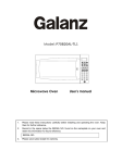
QUICK 3202 Lead Free Soldering Station OPERATION MANUAL Thank you for purchasing the unit. It is designed for lead free soldering. Please read this manual carefully before use and keep it for future reference. Ⅺ. TIPS 12 3.5 ° 25 45° 3.5 200-H 1.5 200-2C 200-1C 200-0.8C 10 12 10 Page 19 4 200-B 1 200-4.2D 0.8 200-3.2D 0.8 200-2.4D 0.5 200-1.6D 0.5 200-1.2D R0.5 3 3.5 3.7 12 12 2.5 12 2 2 2 200-I 200-2B 12 10 12 12 R1 R0.2 R0 .5 200-SB 45° 45° 45° 12 9 3 2 2 200-K 1.5 200-SK 2 200-J 200-4C 2 7.5 1.2 .2 R0 200-3C 15 12 12 12 12 45° 45° 45° 45° 3 3 2 2 1.5 Table of Contents Ⅰ. Safety Instruction……………………………………………………………1 Ⅱ. Specification…………………………………………………………………3 Ⅲ. Characteristic…………………………………………………………………4 Ⅳ. Connection & Operation the Soldering Iron………………………………4 4.1 Iron Holder………………………………………………………………4 4.2 Connection……………………………………………………………5 4.3 Operation of the Soldering Station…………………………………6 4.3.1 Favorite Temperature Setting…………………………………6 4.3.2 Temperature Setting……………………………………………7 4.3.3 Turn On / Turn Off the Sound…………………………………7 4.3.4 Sleeping and Resume…………………………………………8 Ⅴ. Parameter Setting……………………………………………………………8 5.1 Input Right Password…………………………………………………9 5.1.1 Into the Parameter Setting……………………………………9 5.1.2 Input the Password……………………………………………9 5.2 Parameter Menu………………………………………………………10 5.3 Sleeping Time Set……………………………………………………10 5.4 Work Mode Set………………………………………………………11 5.5 Password Set…………………………………………………………12 Ⅵ. Temperature Calibration…………………………………………………12 Ⅶ. Select a Correct Tip………………………………………………………13 Ⅷ. Use and Maintenance of the Tip…………………………………………14 8.1 Use of the Tip…………………………………………………………14 8.2 Maintenance of the Tip………………………………………………14 Ⅸ. Error messages……………………………………………………………16 Ⅹ. Check and Replace the Soldering Iron…………………………………16 10.1 Check the Soldering Iron……………………………………………17 10.2 Disassembling the Iron Handle……………………………………17 10.3 Measure the Resistance before Replacing…………………………18 10.4 Measure the Resistance after Replacing…………………………18 Ⅺ. TIPS…………………………………………………………………………19 Ⅰ. Safety Instruction WARNING In this instruction manual, “Warning”“ Caution” and “ Note” are defined as followings: WARNING: Misuse may potentially cause death or serious injury to the user. CAUTION: Misuse may potentially cause injury to the user or physical damage to the objects involved. For your own safety, be sure to comply with these precautions. 1. Pull out the iron tip by the needle at the soldering handle holder. the iron tip and the iron tip encloser ①are in together. 2. Pull out the heating element③ towards the iron tip of the iron handle⑧. 3. Push the handle cord(12)lightly forwards and pull the PCB for line connection⑥and handle cord out of the iron handle⑧ (towards the tip of the handle). NOTE: Do not use metal tools such as pliers to remove tip or Tip encloser from the iron handle. 10.3 Measure the Resistance before Replacing NOTE: Measure the resistance when the heating element is at room temperature. CAUTION When the power is on, the tip temperature is very high. Follow the precautions strictly as mishandling may cause burn or fire: Do not use the unit for other applications. Do not touch the metallic parts near the tip. Do not use the product near flammable items. Inform other people in working area that the temperature of this unit could be very high during the work. Power the unit off when the work is finished to avoid danger. Power off the unit and wait till the temperature cools down to room temperature when replace or install the parts. 1. Resistance value of heating element is <4Ω. 2. If the resistance value is not normal, replace the heating element. Refer to the instructions included with the replacement part. 10.4 Measure the Resistance after Replacing After replacing the heating element: 1. Measure the resistance values “a” and “b” to confirm that the leads are not twisted and that the grounding wire is properly connected. 2. The pins of the handle plug are as followings: Pin1: Blue Pin2: Red Pin3: Green Pin4: Metal layer of shielding cord Pin5: White of shielding cord Pin6: White To prevent damage to the unit and ensure a safe working environment, be sure to comply with the following precautions: Only use this unit with rated voltage and frequency (refer to the trademark back of equipment). If there’s any damage to the unit, stop using it. Page 1 Page 18 10.1 Check the Soldering Iron 1. Pull out the plug and measure the resistance value between the pins of the connecting plug when the heating element cooling down to the room temperature. 2. If the value of ‘a’ is different from the values in the following table, replace the heating element or cord assembly. Refer to the following steps. 3. If the value of ‘b’ is over the below value, remove lightly the oxidation in the joint part of the tip and the heat element with sandpaper or steel wool. a. Between pins Element) 4&5 b. Between pins 3& Tip (Heating <4Ω(Normal) <2Ω 10.2 Disassembling the Iron Handle(for example This machine is equipped with a 3-wires grounding plug and must be plugged into a 3-terminal grounded socket. Do not modify plug or use an ungrounded power socket. If an extension cord is necessary, use only a 3-wire extension cord that provides grounding. Do not use the unit for other applications except soldering. Do not rap soldering iron against the workbench to shake off residual solder, otherwise the iron will be damaged by shocks. Do not modify the unit. Only use the original replacement parts. Keep the unit dry. Don’t use or disconnect the unit with wet hands. The soldering process will produce smoke, so make sure the area is well ventilated. While using the unit, don’t do anything which may cause bodily harm or physical damage. Children don’t know the danger of electrical appliances. Keep it away from children. 901A Iron hand) Page 17 Page 2 (2) Ⅱ. Specification Power 220V Power consumption 90W Temperature Range 100℃~500℃ (Decide by working mode) Highest Ambient Temperature 40℃ Temperature Stability ±2℃/Without air flow and no load Tip to Ground Resistance <2Ω Tip to Ground Potential <2mV Heating Element Electromagnetic heater Dimension 96(W)×160(L)×135(H) mm Weight (not including handle length) 1.38Kg Iron hand Can select 901A or 901C iron hand; 901A match 200 tips,901C match 200G tips (3) (4) (5) (6) (7) Choose a low and suitable temperature, this will protect the tip from being oxidized. Use fine point tips only when necessary. The plating on fine precision tips is less durable than the plating on blunter tips. Do not use the tip as a prying tool. Bending the tip will cause the plating to crack, shortening tip life. Use the minimum activation flux necessary to do the job. Higher activation flux is more corrosive to the tip plating. Extend tip life by switch the system off when not in use. Don’t apply pressure to the tip. More pressure does not equal more heat. To improve heat transfer, use solder to form a thermal bridge between the tip and the solder joint. Ⅸ. Error messages Various error messages will be displayed when there is something wrong with the unit. Sensor error: If there is a failure in the sensor or anywhere in S-E the sensor circuit, “S-E” will be displayed and power to the soldering iron handle will be cut off. Heater error: If power cannot be sent to the soldering iron, the H-E display window will show “H-E”. This indicates the possibility of a heater malfunction. Ⅹ. Check and Replace the Soldering Iron * The tip’s temperature is measured by 191/192 thermometer. * Specifications and design subject above may be changed without notice. Page 3 When there is something wrong with the soldering iron, you can check and test it. If it is broken, replace the broken element. Page 16 (2) When the temperature is stable, clean the tip with the cleaning sponge, check the condition of the tip. (3) Coat the tip with solder if there is black oxide around it, then clean it with sponge. Repeat until the black oxide is completely removed. Then coat the tip with solder again. This will protect the tip from oxidation and prolong lifetime of it. (4) If the tip is deformed or heavily eroded, replace it with a new one. 2. Why a “de-tinned” tip fails to work? A de-tinned tip is one which cannot wet with solder. This exposes the plating to oxidation and degrades the heat transfer efficiency of the tip. The de-tinning is caused by: (1) (2) (3) (4) (5) Failure to keep the tip covered with fresh solder while not in use. High tip temperatures. Insufficient melting in soldering operations. Wiping the tip on dirty or dry sponges and rags. (Always use a clean, wet, industrial grade, sulfur-free sponge.) Impurities in the solder, iron plating, or on the surfaces to be soldered. Ⅲ. Characteristics 1. With temperature compensation function and the temperature is precise. 2. Display the temperature with the LCD by microcomputer. Quick heating and thermal recovery. Especially it is suitable to the lead free soldering. 3. There are three favorite temperatures. During the work, the temperature can be set, saved or select. 4. Plug in-out type iron tip and heating element, and replacing is convenient. 5. Digital calibration and operate is convenient and easy. Lock the calibration and the parameter setting with the password. 6. Soldering iron handle is portable and comfortable to use. 7. The appearance is novel and the frame is solid. Ⅳ. Connection & Operation the Soldering Iron 4.1 Iron Holder 1. On the iron handle holder, it can place the soldering iron handle, clean sponge, metal sponge and replacing tips. Place them as the following picture. Put the replacing tips 3. To restore a de-tinned tip (1) (2) (3) Put the iron handle Remove the tip form the solder handle and allow the tip to cool down. Remove scale and oxides from the timed area of the tip with 80-grit abrasive polyurethane foam stock or a 100-grit emery cloth. Put the metal sponge Put the clean sponge Wrap rosin core solder (φ0.8mm diameter or larger) around the newly exposed iron surface, insert the tip into the handle, and turn on the power switch. Be used to pull out the tip enclosure NOTE: The de-tinned tips are preventable by proper daily care! 4. Extending tip life (1) Coat the soldering tip with solder before and after using each time. This can prevent the tip from being oxidized and prolong the lifetime of it. Page 15 2. The clean sponge and metal sponge both are used for cleaning the tip and prolonging the life of the tip. Page 4 (1) Use about the clean sponge. Dampen the small cleaning sponge with water and then squeeze it dry. Place the small sponge in groove of the iron holder base. Add a little water to iron holder. The small sponge will absorb water to keep the large sponge around it wet at all times. Dampen the large cleaning sponge and place it on the iron holder base. CAUTION: The clean sponge is compressed. It will swell when moistened with water. Before using the unit, moisten the sponge with the water and squeeze it dry. Failure to do so may result in damage to the soldering tip. If the sponge becomes dry during work, add appropriate water. (2) Use about the metal sponge. When cleaning the tip with the metal sponge, insert the tip into the metal sponge and then revolve it lightly, after cleaning, coat it with fresh solder. Ⅷ. Use and Maintenance of the Tip 8.1 Use of the Tip 1. Tip temperature High temperature will shorten lifetime of the soldering tip. Choose a low and suitable soldering temperature if possible. With the excellent thermal recovery, it can ensure a sufficient and effective soldering event at low temperature to protect sensitive components from damage. 2. Cleaning The remnant flux during soldering process will form oxides and carbides which will cause damage to the tip, soldering difference and thermal recovery decreasing. Clean the tips regularly with the cleaning sponge. Remove the oxides and carbides once a week if using the soldering station continuously to protect the tip. 3. When not in use When the work is finished, don’t leave the soldering station at high temperature for long time. Or the flux in the tip will turn to oxides and carbides which will reduce the heat conductivity of the tip largely. 4.2 Connection CAUTION: Be sure to turn off the power switch before connecting or disconnecting the unit. Failure to do so may damage it. 1. Connect the connector of the iron handle cord to the handle socket of the unit. Take notice of the inserting position about the connector. 2. Place the soldering iron handle into the iron holder. 3. Insert power plug into grounded power socket. 4. Turn on the unit. 4. After use Wipe the tip and coat it with fresh solder. This will protect the tip from oxidation. 8.2 Maintenance of the Tip 1. Inspect and Clean the Tip CAUTION: Never file the tip to remove oxide. (1) Set the temperature to 250℃. Page 5 Page 14 3. Press the “▲” & “▼” buttons simultaneously, press the “*” button until the LCD displays “CAL” to enter the calibrating temperature mode. 4. When the 100’s digit starts to flash, select the value by pressing “▲” or “▼” button according to the reading of the thermometer and then click “*” button to confirm it. Input the 10’s digit and 1’s digit as the method, after that, click “*” button. Here, the calibration operation has been finished. If temperature is successful, the LCD will display “ ” and then return to the work state. 5. Repeat the above steps if there’s any difference between the thermometer and soldering station. NOTE: (1) Recommend using the tip thermometer to measure the tip’s temperature. (2) If locked by password, it will not be able to calibrate the temperature and it must input the right password. Ⅶ. Select a Correct Tip 1. A tip which can contact surface of the soldering joint effectively will conduct heat effectively. 2. Select a tip which can conduct heat to the solder joint quickly and effectively. A short tip can control the process more precise, and a long or angled tip will be more suitable for components-intensive PCBs. Page 13 4.3 Operation of the Soldering Station NOTE: When the password is 000 or it has inputted right password, it can set the temperature real-time, or else, it cannot do the temperature setting and calibration. If the power supply is cut off when setting temperature, the setting value cannot be stored into the unit. CAUTION: Before operation, please check whether the voltage is according with the rated voltage on the unit’s nameplate. 4.3.1 Favorite Temperature Setting 1. There are three favorite temperature states in each working mode. After into the working state, it can set and save the favorite temperature, the method of coming into the favorite temperature setting state is as followings: (1) In the working state, it can switch among the three favorite temperature state by clicking the “*” button and then loosen it. (2) In the selected favorite temperature interface, the LCD displays the set temperature (Set Temp) and real temperature (Real Temp). 2. If the unit is locked by the password, it only can select the favorite temperature value, but cannot set and save the favorite temperature value. 3. If the password is 000 or the inputting password is right, it can set and save the favorite temperature value. (1) SET FAVORITE TEMPERATURE VALUE: after selecting the favorite temperature mode, click the “▲” or “▼” button to set the favorite temperature value (The setting method can refer to the “4.3.2 temperature setting”). (2) SAVE FAVORITE TEMPERATURE VALUE: If need to save the set favorite temperature value, after setting, it must press the “*” button and not loosen until the LCD displays “ ”, which means the favorite temperature saving is successful. Or else, the temperature is not saved. Page 6 3. After selecting the working mode, click “*” button to save and then return to the parameter menu selecting interface. 4.3.2 Temperature Setting Raise Temperature: Click “▲” button, the temperature will rise1℃, the LCD will display the current setting temperature. If press the “▲” button for at least 1s, the setting temperature will rise rapidly. Loose the “▲” button when the value is up to the required temperature. Reduce Temperature: Click “▼” button, the temperature will drop1℃, and the LCD will display the current setting temperature. If pressing “▼” button not loosely at least 1s, the setting temperature will drop rapidly. Loose the “▼” button when the value is down to the required temperature. 4.3.3 Turn On / Turn Off the Sound 5.5 Password Set 1. In the parameter menu selecting interface, click “▲” or “▼” button to select the menu “-4-”, and then click “*” button into the password setting interface. 2. Once into the new password setting, the LCD displays “---”. After that, click the “▲” or “▼” button, the 100’s digit is bright. 3. At the time, click the “▲” or “▼” button to select the 100’s digit, and then click the “*” button when displaying the selected value of 100’s digit. After that it comes into 10’s digit set. The setting methods of the 10’s digit and 1’s digit are same with the 100’s digit. 1 2 3 4 5 6 7 8 9 0 1. In the working state, press the “▲” and “▼” buttons simultaneously and keeping about 3seconds. The sound will be turned on if the LCD displays 4. If the setting passwords are not same with each other, it will return to the work state directly, which means the password setting is not successfully. “ ”, and will be off if the LCD displays “OFF”. 2. When the sound is turn on (the sign displaying on the screen), it has sound when clicking the button. displaying on the screen), if the 3. When the sound is turned on (the sign difference in temperature between real temperature and set temperature is bigger than ±20℃, it will sound to prompt. 4. If the sound is turned off (the sign don’t displaying on the screen), it is soundless when clicking the button or the difference in temperature is bigger than ±20℃. ”, 5. If the setting passwords are same with each other, the LCD displays “ and then return to the parameter menu selecting interface, which means the password setting is successfully. Page 7 Ⅵ. Temperature Calibration The temperature of the unit should be recalibrated every time if the handle, heating element or soldering tip is replaced. The unit uses digital calibration. Method of recalibrating temperature: Use the thermometer to calibrate it and it is precise comparatively. 1. Set the temperature at a certain value. 2. When the temperature is stable, measure the tip’s temperature with thermometer and write down the value. Page 12 2. In the sleeping time setting interface, click “▲” or “▼” button to adjust the sleeping time. The sleeping time setting range is “00~99” or “--” (unit: minute). 00: means when putting the soldering iron handle on the soldering holder, it will come into the sleeping state at once. 01~99: means when putting the soldering iron handle on the soldering holder, it comes into the sleeping state after the setting time. --: means the soldering iron will not come into the sleeping state. 3. After finishing setting the sleeping time, click “*” key to save and then return to the parameter menu selecting interface. 5.4 Working Mode Set 1. In the parameter menu selecting interface, click “▲” or “▼” button to select the menu “-3-”, and then click “*” button into the working mode setting interface. The default working mode is 01, such as the following picture. 4.3.4 Sleeping and Resume 4.3.4.1 Sleeping and waiting 1. The screen displays “---” and “sleep” after into the sleeping state. 2. In the sleeping state, if the setting temperature is higher than 200℃, the sleeping temperature is 200℃. If the setting temperature is lower than 200℃, the sleeping temperature is the setting temperature. 3. If don’t do some operation during one hour after it comes into the sleeping state, the system will display “OFF” and come into the waiting state. 4. The sleeping time can be set. To select menu “-2-” in the parameter menu selecting interface and it can set the sleeping time. The sleeping time range is “00~99minutes/--”. The setting method can refer to “5.3 sleeping time set”. 4.3.4.2 Resume Resume the soldering state from sleeping state or waiting state:Take up the soldering iron handle from the soldering holder,the unit will come into the working state. Working mode setting interface 2. In the working mode setting interface, click “▲” or “▼” button to select working mode, the working mode changing sequence is as following: 00 01 02 Ⅴ. Parameter Setting NOTE: 03 The initial password is “000”. Only when the inputting password is right or the password is 000, it can enter into the parameter setting. If want to limit the Working Mode Table temperature change, it needs to change the password. Working Mode Temperature range 00 100℃-350℃ 01 100℃-400℃ 02 100℃-450℃ 03 100℃-500℃ Page 11 The parameter setting is including sleeping time setting, work mode setting and password setting. Page 8 5.1 Input Right Password 5.2 Parameter Menu 5.1.1 Into the Parameter Setting 1. Turn off the power switch. And then press the “ ▲ ” & “ ▼” buttons simultaneously, afterwards, turn on the power switch. 2. It can loosen the “▲” & “▼” buttons until the screen shows , Which means it has come into the parameter setting mode. 5.1.2 Input the Password NOTE: There are twice chances to input password and if the inputting password for the first time is wrong, it can input the password again. If the inputting password is wrong for the two times, it cannot come into the parameter setting, namely it cannot set the work mode and new password and the temperature setting is locked after into the work mode. 1. After into the parameter setting mode, the screen displays “---” and the 100’s cursor is flicker, which means it needs to input the password. 2. Input password: Click the “▲”or“”button to input 100’s digit, and then click the “*” button. After that it comes into 10’s digit input. The inputting methods of the 10’s digit and 1’s digit are same with the 100’s digit. After selecting the 1’s digit, click “*” button. 3. If the inputting password is wrong for the first time, it comes into the password-inputting interface again and the screen displays “---”. Input the password again as the step 2. 4. If the inputting passwords both are wrong, it cannot come into the parameter setting and return to the work state directly. 5. If the inputting password is right at the first time or the second time, it comes into the parameter setting. Firstly, the screen displays “-1-”. Page 9 There are four parameter menus and it can switch among them by clicking “▲” or 1 2 3 4 . “▼” button. The switching order is as: -1-: this menu has “Exit” function. Click “▲” or “▼” button to select the menu “-1-” and then click “*” button. It exits from the parameter setting and comes into the work mode. -2-: this menu has “Sleeping Time Setting” function. Click “▲” or “▼” button to select the menu “-2-” and then click “*” button. It comes into the sleeping time setting interface and the setting method can refer to the “5.3 sleeping time set”. -3-: this menu has “Working Mode Setting” function. Click “▲” or “▼” button to select the menu “-3-” and then click “*” button. It comes into the work mode setting interface and the setting method can refer to the “5.4 working mode set”. 4-: this menu has “Password Setting” function. Click “▲” or “▼” button to select the menu “-4-” and then click “*” button. It comes into the password setting interface and the setting method can refer to the “5.5 password set”. 5.3 Sleeping Time Set 1. In the parameter menu selecting interface, click “▲” or “▼” button to select the menu “-2-”, and then click “*” button into the sleeping time setting interface. The default sleeping time is 20minutes, so the screen displays “20”. Sleeping time setting interface Page 10