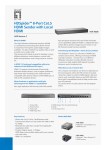
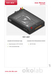
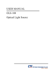
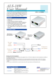
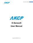
1
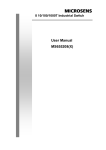
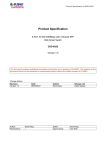
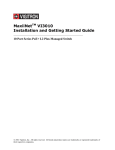
Introduction CTC Union Technologies Co., Ltd. The IFC-1000PSE is an electrical copper to optical fiber Gigabit Ethernet solution designed to make conversion between 10/100/1000Base-T and 1000Base-SX/LX with SFP module. The IFC-1000PSE complies with IEEE802.3af Power Over Ethernet standards and has a built-in AC power supply. This PoE (Power over Ethernet) media converter is a Power Sourcing Equipment (PSE) which combines data received over a TP link with 48VDC power, providing power to IEEE802.3af powered device (PD) over the existing CAT5e or CAT6 UTP cable. Other features include Link Fault Pass through (LFP), Store and Forward Switching, and auto or forced mode setting for copper Ethernet. w w w . c t c u . c o m User Guide Gigabit Ethernet PSE Fiber Media Converter •IFC-1000PSE-AC •IFC-1000PSE/A Features 10/100/1000Base-T to 1000Base-SX/LX SFP IEEE 802.3af-2003 PSE (power sourcing equipment) Auto-negotiation or forced mode on UTP Auto MDI/MDIX Store and Forward Switching Mechanism Forward 1632 bytes (max.) packet Supports 4k MAC address Supports 256K bytes packet buffer Supports Link Fault Pass through (LFP) function For applications including IP Cameras, IP phone and wireless Access Points that require less than 15W [email protected] Panel [email protected] V1.2 Specifications Standards IEEE802.3 10Base-T, IEEE802.3u 100Base-TX IEEE802.3ab 1000Base-T, 802.3z 1000Base-SX/LX IEEE802.3x flow control IEEE802.3af -2003 PSE (Power Sourcing Equipment) 10/100/1000Base-T RJ-45 Connectors Dip Switch One RJ-45 connector is provided for connection to either MDI-X (to PC) or MDI (to HUB) equipment. Utilizing auto MDI/MDIX allows all UTP connections to be made using only a common straight-through UTP cable. 10/100/1000T GbE Port with PSE 48V, 15W LED Indicator (SPD, Duplex, LFP) 1000X SFP Cage (shown with SFP) • Figure #1. Front Panel of IFC-1000PSE PSE Output Power Class 0 : 15.4W , Class 1 : 4W, Class 2 : 7W, Class 3 : 15.4 w RJ-45 Pin Assignment Pin 1 TX/RX A+ V+ Pin 2 TX/RX A V+ Pin 3 TX/RX B+ VPin 4 TX/RX C+ Pin 5 Pin 6 Pin 7 Pin 8 TX/RX C TX/RX B TX/RX D+ TX/RX D - V- Fiber Optic Connectors • Figure #2. Rear Panel of IFC-1000PSE-AC One SFP cage is provided for SFP fiber optic transceiver. IFC-1000PSE with SFP requires duplex LC connector cable SFP for single fiber BiDi may have single LC or SC connector. Environment Temperature: Operating -- 0 to 50℃, Storage - 0 to 70℃ Humidity: -- 10 to 90%, (non-condensing) Power : IFC-1000PSE-AC : Internal AC 100 ~ 240VAC ±10% IFC-1000PSE/A : External DC 48V in AC adapter • Figure #3. Rear Panel of IFC-1000PSE/A Dimensions: 147 x 162 x 36 (D x W x H)mm Net Weight: 405g [email protected] [email protected] LED Indicators Dip Switch Setting PWR 100/1000 PSE The IFC-1000PSE is provisioned through the use of a single 4pole DIP (Dual Inline Package) switch located on the front panel. Setting a switch down places it in the ON position. FULL FX LNK UTP LNK Switches 1&2 provide setting auto-negotiation (Nway) or manual forced speed of 10, 100 or 1000. Default is all OFF. LED Function State Status PWR Converter Power ON OFF Power on Power off PSE PSE Status ON OFF PSE power in-use PSE standby FX LNK Fiber link Status ON OFF Fiber link is ok No Fiber link 100/1000 LAN Speed Status Orange Green OFF 1000Mbps 100Mbps 10Mbps FULL LAN Duplex mode ON OFF Full duplex Half duplex UTP LNK UTP link Status ON OFF UTP link is ok No UTP link [email protected] Installation Connect the Ethernet cable to the IFC-1000PSE. The converter will sense whether to operate in Full or Half mode and will be indicated on the LED. Follow the connection examples below. Connections The following example illustrates the connection scheme when connecting from IP Camera and VoIP Phone to 10/100/1000Base-T UTP port through the IFC-1000PSE fiber converter. Switch 3, when ON (down), sets the forced Half Duplex for either 10Base or 100Base, or sets Full Duplex when OFF (up). Switch 4 is used to enable the LFP (Link Fault Pass-Thru) function. LFP is enabled when the switch is ON (down). ON [email protected] Link-Fault-Pass Through (LFP) Note This media converter incorporates a fiber link pass through feature which allows indirect sensing of a fiber link loss via 10/100/1000 Base-TX UTP connection. Whenever the media converter detects a link loss condition on the receive fiber (FX LNK Off), it disables its UTP transmitter so that a link loss condition is sensed on the receive UTP port. (See the following figure) The link loss can then be sensed and reported by network management agent at the remote UTP port’s host equipment. The LFP feature has no effect on the media converter’s UTP Link LED, which continues to function normally, independent of the state of the fiber LNK LED and the UTP transmitter. This feature is disabled by default from the factory. [email protected] [email protected]