1
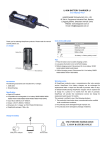
ASunDar Users Manual ASD907 MINI Electronic Load VR:0.91 Shenzhen Asundar Electronics Co., Ltd www.asundar.com Shenzhen Asundar Electronics Co.,Ltd Foreword Thank you for purchasing the product of Shenzhen Asundar Electronics Co.,Ltd! This manual describes how to use ASD907 MINI electronic load (referred to as the product in this manual). Before use, please read this user manual carefully. Attentions When open the package, make carefully inspection and confirm that ① product model is consistent with your order ② product certificate, user manual and warranty card and other accessories are complete. ③ If there is any damage or missing during transport, please contact the company or your supplier to solve. Before power on, please check the input voltage is within the scope of the rated parameters, If the voltage is beyond the scope, the product can't work, or cause burning out, or even serious consequences Please make sure that the ground lead of power input end is safe, or otherwise it may cause electric shock! Due to the product upgrade or specification updates, and in order to improve the accuracy of manual description, this manual will be updated in a timely manner, and if there lies the difference between manual and actual use of, please refer to the latest version or contact our customer service. If you still have any queries in reading the manual, please contact company customer service. Customer service phone:0755-28531900 400-0755-308 -1- Shenzhen Asundar Electronics Co.,Ltd Contents 一、Product Introduction------------------------------------------------------------------------- 3 二、Technical specifications-------------------------------------------------------------------- 3 三、Quick Start -------------------------------------------------------------------------------------- 3 四、Environmental Requirements ------------------------------------------------------------ 9 五、Warranty ------------------------------------------------------------------------ --------------- 10 -2- Shenzhen Asundar Electronics Co.,Ltd 一. Product introduction ASD907 MINI electronic load is mainly used for the performance evaluation and testing for power bank. It is a multifunctional MINI electronic load. Can be used for R & D, production line testing, debugging (quality) performance evaluation etc Main Function 2.4 inch color LCD screen display; High precision and high resolution ratio 1mV/1mA; High stability, low ripple, low drift; Easy operation; Can test output parameter of power bank; Can test charging time and charging energy of power bank; Can test discharging time and discharging energy of power bank; 二、Technical specifications item Input Programming resolution Readback resolution Parameter Specification index Voltage 0-10V current 0-4A Voltage 1mV current 1mA Voltage 0-5V 5-10V 1mV 2mV current 1mA Readback accuracy Voltage 0.05% +2mV (@25°C) current 0.15% +4mA Voltage scope 5.0V ±0.25V Current consumption 150mA-500mA Equipment size HxWxD 99.5mm*150mm*36.5mm Packaging size HxWxD 180mm*330mm*350mm Net weight 405g Gross weight 525g power input Weight 三、Quick Start This chapter will introduce the appearance and basic function of ASD907 MINI electronic load, and let you quickly understand and use the ASD907 MINI electronic load. 3.1 ASD907 MINI electronic load panel introduction -3- Shenzhen Asundar Electronics Co.,Ltd ② ① ③ ④ ⑤ Figure 1:ASD907 display panel ①LCD display area ④ ▼ down key ② ▲ up key ③“ON/OFF/ENT”key ⑤“MENU/ESC”key ① Figure 2 :ASD907 rear panel ① Heat radiating window 1 ② Figure 3:ASD905 left and right panels ① load input ② power input -4- Shenzhen Asundar Electronics Co.,Ltd 3.2 Basic operation 3.2.1 quick start: Connect ASD907 MINI electronic load to the power, LCD will appear start LOGO,as Figure 4 shows. After waiting a few seconds of system initialization, electronic load shows the standby interface, as shown in figure 5, which means a smooth start. Figure 4:start LOGO Figure 5: standby interface You can start test function by pressing "ON/OFF" key in the standby interface. In constant current mode, the operation display interface is as shown in Figure 6. The left side of the interface shows the actual tested parameters,the “on”mark at the bottom of left corner means the product is in operation. The red display on top right corner shows the value of the set constant current, Can adjust or modify the parameter by a short press on "▲" or "▼" key in both running mode or standby mode.(the long press will switch the control gear). Below the display of the tested parameter, it is electronic energy accumulation value. The unit is W·h. Please reset the parameter to zero before use. Otherwise the previously tested value may be added to the current value.The reset method is to press “ENT”button over 2 seconds and can clear the parameter to zero. The bottom of the right corner of the parameter display shows the working temperature of the product. When the working temperature is below 30℃, the color of the displayed value will be green. When the working temperature is between 30℃ to 40℃, the parameter color will be yellow. When the working is higher than 40℃,the parameter color will be red. It is not recommended to use the product for a long time when the working temperature is higher than 40℃, please reduce power consumption or increase the auxiliary cooling measures. -5- Shenzhen Asundar Electronics Co.,Ltd set parameter parameter in current mode accumulated electronic energy working temperature Figure 6:constant current mode display interface Figure 7 shows the display interface of the constant voltage mode. The interface of constant voltage mode and the interface of constant current mode are very similar. Can adjust or modify the setting parameter by a short press on "▲" or "▼" key in both running mode or standby mode.(the long press will switch the control gear). Please refer to constant current mode operation method for more operation information. set parameter parameter in current mode accumulated electronic energy Working temperature Figure 7: Constant voltage mode display interface Figure 8 shows the display interface in the mode of battery capacity test. The left side of the interface shows the actual tested parameters, the “on”mark at the bottom of left corner means the product is in operation. The red display on top right corner shows the set constant current discharge value, press “▲”or “▼”key to adjust the parameter in the standby mode. Below the display of the tested parameter, they are respectively timer, volume, total electronic energy. It is suggested to make these parameters clear before use. Otherwise the previously tested value may be added to the current value. Press “ENT”button over 2 seconds can clear the parameter to zero. -6- Shenzhen Asundar Electronics Co.,Ltd set parameter parameter in current mode timer capacity accumulated Electronic energy accumulated Figure 8: Capacity test mode display interface 3.2.2 working mode setting Press “MENU”button after the boot of MINI electronic load and get “setting”interface, as shown in Figure 9. Press “▲”or“▼”key to select working mode, press “ENT”button to enter into working mode select interface, see Figure 10. In working mode interface, press ▲”or“▼” key to select one of the following working mode of “constant current mode”, “constant voltage mode”or “capacity test”.select the needed working mode according to your requirements and then press “ENT”to confirm(press “ESC”button to return to the MENU interface),the product will enter into standby interface of the corresponding working mode, click "ON/OFF" button to start the test function in the standby interface, and you can click "ON/OFF" button to stop the current test in operating interface. Figure 9: setting interface 3.2.3 Figure 10:working mode setting interface Extended function setting Press “MENU”button after the boot of MINI electronic load and get “setting”interface, to select “function setting”by pressing “▲”or“▼”key, press “ENT”button to enter into function setting interface, as shown in Figure 11.In function setting interface, press “ ▲”or“▼” key to select one of the following functions of “discharge termination voltage judgment”, “timing shutdown”or “USB online”. Choose one kind of function according to the need and press “ENT”button, enter into the “start”or “cancel”interface for confirmation, to select “start”or “cancel”by pressing “ ▲”or“▼” key. Press "ENT" button to set the corresponding function on or off, and press “ESC” button to return to the previous menu. During the whole setting process, “ESC” button will bring you to previous menu. -7- Shenzhen Asundar Electronics Co.,Ltd Discharge termination voltage judgment: it needs to start discharge termination voltage function when test the battery capacity, and should set the corresponding discharge termination voltage value. Timing shutdown: mainly used to set up a discharge delay time. When this feature is turned on and the shutdown time is set in parameter, the product will automatically switch to shutdown status from operating status. USB online: mainly used for the online communication function between the MINI electronic load and the host computer. (Note: ASD907 does not support USB online function, ASD907 extended version can support this feature) Figure 11: function setting interface 3.2.4 parameter setting Press “MENU”button after the boot of MINI electronic load and get “setting”interface, to select “parameter setting”by pressing “▲”or“▼”key, press “ENT”button to enter into parameter setting interface, as shown in Figure 12. In parameter setting interface, press “ ▲”or“▼” key to set following 4 parameters of “ constant current value”, “constant voltage value”“ “discharge termination voltage value”and “shutdown time”. Choose one parameter according to the need and press “ENT”button to confirm and then enter into the parameter interface. By pressing "▲" key to increase the setting value, and "▼" key to reduce the set value. The short press can adjust the parameter slowly and long press can adjust quickly. And then save the set parameters by pressing “ENT” button. Press “ESC” button to be back to working interface. (During the whole setting process, “ESC” button will bring you to previous menu.) -8- Shenzhen Asundar Electronics Co.,Ltd Figure 12: parameter setting interface 3.2.5 language select Press “MENU”button after the boot of MINI electronic load and get “setting”interface, then press “▲”or“▼”key to select language, press “ENT”button to enter into language select interface, see the figure 13. In the interface of language selection, press ▲”or“▼”key to select “Chinese”or “English”,and then press “ENT”to confirm or press “ESC”to return. Figure 13: language select interface 四. Environmental Requirements Item Parameter temperature Working environment humidity dust altitude Storage environment temperature humidity Specification index 0°C - 55°C (if temperature exceeds 40° C, please reduce power dissipation) Max: 85% degree of pollution: grade 2 Below 2000 meter -30°C ~ 70°C Max: 90% -9- Shenzhen Asundar Electronics Co.,Ltd 五. Warranty 1. One year warranty is provided from the date of purchase(according to the issue date of the invoice) 2. The following is not within the scope of the warranty: 3. 4. 5. 6. 7. 8. A. The damage caused due to transportation, improper use or keeping (such as liquid, damp,external pressure, falls, etc) B. Repair or reconstruction is not approved by our company C. the damages due to natural disasters (such as: lightning, earthquake, fire, flood, etc.) and secondary disasters; D. Faults and damages are not caused by the machine itself. E. Lack of complete procedures of warranty card and purchase receipt F. Accessories are not within the scope of the warranty. Product failure or damage, please correctly fill in the Warranty Card in detail. Product warranty card generally has no replacement, please keep this card well. After warranty period, we will provide paid service for more lasting perfect after sale service. Repair fee will be charged in accordance with the latest price list. If there has any queries, please do not hesitate to contact our agent or company. The Agreement shall be explained by Shenzhen Asundar Electronics Co.,Ltd. Shenzhen Asundar Electronics Co.Ltd Office Add:Room 902,Building A, Hongshengyuan Industrial Zone, 339 Bulong Road, Bantian Town, Longgang Dist, Shenzhen, Guangdong ,China Factory Add::3/F, Building 1, Jiaan Science & Technology Garden, Baoan 67 District, Shenzhen City, China Tel:86-755-28531900 Http:www.asundar.com --10-- Fax:86-755-28530909