1
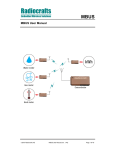
KNX
KNX User Manual
2010 Radiocrafts AS
KNX User Manual (rev. 0.30)
Page 1 of 22
KNX
Table of contents
TABLE OF CONTENTS ............................................................................................................ 2
QUICK INTRODUCTION .......................................................................................................... 3
KNX FEATURE SETS............................................................................................................... 4
OPTIONAL CUSTOM SPECIFIC VERSION ............................................................................ 4
NETWORK TOPOLOGY........................................................................................................... 5
KNX-RF EMBEDDED PROTOCOL .......................................................................................... 6
BASIC FUNCTIONALITY .............................................................................................................. 6
UART INTERFACE FOR KNX-RF PACKET HANDLING................................................................... 7
FRAME FORMAT FOR TRANSMITTING DATA .................................................................................. 7
FRAME FORMAT FOR RECEIVING DATA ....................................................................................... 8
UART INTERFACE FOR MODULE CONFIGURATION...................................................................... 9
UART TIMING INFORMATION ................................................................................................... 10
POWER MANAGEMENT ............................................................................................................ 12
RSSI READING ...................................................................................................................... 12
KNX1 DESCRIPTION ............................................................................................................. 13
KNX1 AUTOMATIC SLEEP ....................................................................................................... 13
KNX1 INSTALLATION AND BINDING .......................................................................................... 13
KNX1 TIMING TABLE .............................................................................................................. 14
[TABLE TO BE UPDATED].......................................................................................................... 14
KNX1 CONFIGURATION COMMANDS........................................................................................ 15
KNX1 CONFIGURATION MEMORY ............................................................................................ 17
APPENDIX: CONFIGURATION MEMORY FACTORY DEFAULT........................................ 20
APPENDIX: ASCII TABLE ..................................................................................................... 21
DOCUMENT REVISION HISTORY......................................................................................... 22
DISCLAIMER .......................................................................................................................... 22
TRADEMARKS ....................................................................................................................... 22
LIFE SUPPORT POLICY ........................................................................................................ 22
CONTACT INFORMATION..................................................................................................... 22
2010 Radiocrafts AS
KNX User Manual (rev. 0.30)
Page 2 of 22
KNX
Quick Introduction
How do I transmit data?
Send your data to the RXD pin on the module. Use the UART format with settings (19200, 8,
1, N, no flow control). Up to 255 bytes are buffered in the module. The first byte of the
message should contain the message length. The module will transmit the data when the
whole packet is received.
How do I receive data?
Any received data packet with correct KNX-RF format and check sums will be sent on the
TXD pin. Optionally the meter address (first KNX block) is added to the data string. The RSSI
value (received signal strength) can optionally be added to the message.
What about the antenna?
In most cases a simple quarter wavelength wire or a PCB track will do. Connect a piece of
wire to the RF pin with length corresponding to the quarter of a wavelength. For space limited
products, contact Radiocrafts and we will recommend the best antenna solution for your
application.
How do I change the operating mode or any other parameter?
To change configurable parameters, send one byte to the module with the value 0x00. This
will take the module into configuration mode. Special commands are then used to access the
configuration registers and test modes. Exit from configuration mode by sending the ‘X’
command. Parameters can be changed permanently and stored in non-volatile memory in the
module.
2010 Radiocrafts AS
KNX User Manual (rev. 0.30)
Page 3 of 22
KNX
KNX feature sets
This User Manual describes the embedded protocol of the KNX Modules from Radiocrafts.
The KNX firmware is available as different feature sets targeting specific applications. The
hardware platform is the same for all solutions, and the different feature sets available are
listed in the table below. Detailed information on how to use the different feature sets is found
in this User Manual.
There are four KNX RF specifications:
• KNX RF Ready is a single channel system at 868.3 MHz, and is an update of KNX
RF revision 1.1 specified in EN 50090-5-3:2006
• KNX RF Multi is a multichannel evolution of KNX RF Ready system with to additional
RF channels for fast reaction time products and two RF channels for slow reaction
time products
• KNX BiBat is a system for synchronised products based on KNX 1.1 specification
• KNX BiBat 2 is an evolution of BiBat with two RF channels based on KNX 1.1
specification
For additional information about the KNX RF packet structure, please see EN 50090-53:2006, and KNX System Specifications part 3.2.5, Communication Media, Radio Frequency.
Feature List
General
Network role
KNX packet
handler
Modes
Addressing
Number of
installed serial
number
Filter function
Listen before
talk (LBT)
KNX1
Basic KNX-RF 1.1
and KNX Ready
functions
Sender and Receiver
Yes
TBD
Feature set
KNX2
TBD
KNX3
S1, S2
Serial and domain
addressing
Up to 64
Receiver only
receives messages
from
installed/registered
group addresses
Yes, according to
KNX
The command set used to configure the KNX modules are different for each feature set and
an overview is found in the appendixes.
Note that this User Manual also is applicable for the RCxxxxTX-KNX (planned future product).
This is a TX only hardware and the RX features described in this User Manual is not
supported.
Optional custom specific version
As an option to the standard feature sets, a full KNX application layer can be integrated in the
module based on customer specification. In this case all the application layer protocol and
timing will be handled internally by the module. See Data Sheet for details.
2010 Radiocrafts AS
KNX User Manual (rev. 0.30)
Page 4 of 22
KNX
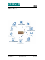
Network Topology
A KNX based building automation system normally consists of a number of sensors which
reports their readings and status to a concentrator for further processing, or directly trigging
actuators. The network topology is one-to-many or peer-to-peer. KNX-RX 1.1 or KNX RF
Ready does not use the Master – Slave concept of for example Wireless M-Bus. Several
receivers can receive the same message based on registering the group (or individual)
address of the transmitter.
The Radiocrafts KNX-RF family of modules RC11xx-KNXx can be used as transmitters or
receivers. The module is configured with a unique address (Serial Number), and a Domain
Address, and when sending a reading or command this address is added to the wireless
message. Up to 64 transmitter addresses (the 6 bytes of the extended address) can be
registered in the receiver, which will filter messages from only these transmitters.
Sensors being transmitters only can be battery operated as they can by set in sleep mode
when not transmitting. For two-way battery operated systems, the new KNX BiBat (Bidirectional Battery operation) specification applies.
A re-transmitter can be used to increase the range of the RF system. Messages from
transmitters that have been registered in the re-transmitter will be re-transmitted.
2010 Radiocrafts AS
KNX User Manual (rev. 0.30)
Page 5 of 22
KNX
KNX-RF Embedded Protocol
Basic functionality
The module offers a buffered packet radio acting as a KNX modem. The module contains a
fully embedded protocol supporting:
• Unidirectinal devices (transmit only, S1)
• Bi-direction devices (S2)
The mode is configurable by the KNX_MODE parameter.
The required KNX mode is configured by setting the module in configuration mode and
entering appropriate UART commands.
S2-mode:
Set KNX_MODE = 0
Set PREAMBLE_LENGTH = 0 (for short preamble) or 1 (for long preamble).
S1-mode:
Set KNX_MODE = 3
Set PREAMBLE_LENGTH = 0 (for short preamble) or 1 (for long preamble).
KNX Ready use the long preamble, while KNX RF 1.1 use short preamble.
The RF channel (868.3 MHz) and data rate (32.768 kchip/s) are set internally in the module
according to S mode.
The module has an internal buffer and transmits application data after the whole packet is
received based on the packet length (first byte of the application frame). The module use
Listen Before Talk (LBT) to avoid collisions. The module will listen for a preamble for 15-30
ms (at random) and only transmit if the channel is free. If a preamble is detected, the module
will wait until that message has been completed, and will then again listen for a new preamble
for another 15-30 ms (at random), until the channel is free.
Optionally (configurable) the module will send a “Transmission complete” message (“Length =
00h, followed by 3Fh) on the UART when the transmission has been done.
For uni-directional devices (S1 transmit only), data should not be sent to the module more
frequent than every 150 ms. The data packets should also have a random spacing of 0-10 ms
(or more).
The module also has a timeout feature that will empty the input buffer in case of false data
packets. The default timeout is 2 seconds. Max total payload is 246 bytes, or 255 including
the header in the first block.
Sleep mode can be entered via an UART command and wake-up is triggered on UART traffic
(one FFh byte). Sleep mode can also be entered automatically after a transmission
(configurable by SLEEP_MODE) when using the S1 (transmit only) mode.
The module acts as a buffered packet radio, hence all data to be sent is stored in the module
before they are transmitted by the RF circuitry. Likewise, when data is received they are
stored in the module before they are sent to the host. This allows the communication
controller to add address information and CRC during transmission, and to do error check of
the received data.
The Module has an UART interface that is used for both KNX-RF packet data and module
configuration.
2010 Radiocrafts AS
KNX User Manual (rev. 0.30)
Page 6 of 22
KNX
UART Interface for KNX-RF packet handling
The KNX-RF frame format follows the FT3 block format, using two CRC bytes for every 16
data bytes. This ensures the high integrity of the data link.
Preamble
sync
block 1 (10
bytes)
CRC
block 2 (16 bytes) CRC
...
CRC Postamble
The KNX modules include a KNX packet handler that with automatic generation of Preamble
(Header + synchronization), Block 1 (C-filed, RF-info and address), CRC and Postamble. This
will simplify the UART format for the host controller that only need to provide application layer
data to the module UART.
The host use the UART Interface to send and receive KNX-RF data. The UART packet format
can be changed in the configuration mode.
When the Module receives a KNX packet over RF it will send the packet over the UART
interface on the TXD Line. When the host MCU wants to transmit a KNX packet over the RF,
it must send the packet through the UART Interface on the RXD line.
Figure 1: UART interface overview and KNX RF packet format
Frame format for transmitting data
The data frame for the UART RXD pin (input for transmitting a KNX packet) is built like this:
Figure 2: UART interface packet transmission (RXD pin)
2010 Radiocrafts AS
KNX User Manual (rev. 0.30)
Page 7 of 22
KNX
L is the length (not including the length byte itself), followed by the data headers with the CI
byte first. CI is the Control Information byte (or “KNX-Ctrl”). The data headers are L/NPCI
(Link/Network Protocol Control Information), TPCI (Transport layer Protocol Control
Information) and APCI (Application layer Protocol Control Information).
The C-field is fixed to 44h (i.e. SND-NR message). The RF-info contains battery status, which
can also be added by the module based on a configurable voltage threshold
(BATTERY_THRESHOLD) which can be set in 30mV steps. The maximum value is 3.75V
corresponding to 7Fh.
The unique Serial Number (SN) and Domain Address (DoA) are entered and stored in the
modules’ non-volatile memory. Depending on the Application header AET bit in the L/NPCI
field either the SN or DoA will be used.
The Link layer header (L, C-field, RF info and address) is added to the KNX packet
automatically by the module before transmitting over RF. Compared to the KNX frame used
for wired communication like twisted pair, an extended address is used. This is to avoid
conflicts between two adjacent networks. The Group addresses (source and destination
address) is coded in the beginning of the application header.
By setting DATA_INTERFACE = 0x10 (or in combination as 0x11 – 0x1C), the two byte string
00:3Fh (i.e. L = 0) will be sent on the UART when transmission is completed (after LBT).
Frame format for receiving data
The data frame for the UART TDX pin (Output for received KNX packets) is built like this:
Figure 3: UART interface packet reception (TXD pin)
Data in blue and yellow are optional output parts of the UART message and can be enabled
in configuration mode by the DATA_INTERFACE and RSSI_MODE configuration parameters.
L is the length byte and is always present. It does not include itself or the START/STOP
bytes, but will include RSSI and CRC if enabled.
Do also note that the receiving module will add RSSI information within the RF-info byte,
based on received signal level.
When setting DATA_INTERFACE = 1, the received HEADER will not be sent on the UART.
2010 Radiocrafts AS
KNX User Manual (rev. 0.30)
Page 8 of 22
KNX
For host applications using a UART buffer the timing information used for parsing could be
lost. In this case a start and stop byte can be used. Setting DATA_INTERFACE = 4 will add a
START byte (68h) and a STOP byte (16h) to the message. This is only used for the moduleto-host communication direction (TXD). Setting DATA_INTERFACE = 8 will add a two byte
CRC checksum, and DATA_INTERFACE = 0Ch will add START/STOP bytes and CRC. The
CRC is sent MSByte first.
The RSSI value is added when RSSI_MODE = 1.
UART Interface for Module Configuration
The configuration of the module can be changed in-circuit from the host during operation, at
the time of installation of the equipment, at the manufacturing test, or even as a stand-alone
module. The configuration is changed by sending commands on the UART interface after the
module is set in configuration mode. The configuration mode is entered by sending 00h to the
module, or by asserting the CONFIG pin (set low).
In configuration mode the module will respond by sending a ‘>’ prompt on the TXD pin. This
indicates that the module is ready to receive commands. The CONFIG pin (if used) can then
be de-asserted. Note that the CONFIG pin must be de-asserted before the Exit command
(‘X’) is sent to the module in order to return to normal operation.
After a command is executed, the module responds with the ‘>’ prompt character again,
indicating it is ready for a new command. Do not send a new command before the ‘>’ prompt
is received. The time required to execute a command can vary depending on the command
(see the Timing Information section). There is no ‘>’ prompt after the ‘X’ exit command.
The parameters that are set by dedicated configuration commands (‘C’, ‘P’ etc) take
immediate effect after returning to normal operation (IDLE), but will not be stored in nonvolatile memory and will be lost in case the supply power is turned off or if the module is
reset. These parameters are for example the radio channel and output power.
Permanent changes of parameters can be done by writing to the configuration memory using
the memory command ‘M’. These are for example default radio channel, default output power
and M-Bus mode, see the Configuration Memory section for details.
The flow diagram bellow illustrates how to use the UART interface to enter configuration
mode, change configuration parameters and return to IDLE mode.
2010 Radiocrafts AS
KNX User Manual (rev. 0.30)
Page 9 of 22
KNX
Figure 4: Configuration mode flow diagram
UART Timing Information
A UART byte consist of one start bit, 8 data bits, and one stop bit. In configuration mode a
command to prompt reply will looks like this:
Figure 5: UART Command and prompt
The command-to-prompt wait time (T_Command2Prompt_WAIT) is different from command
to command and values are shown in the timing table for each KNX feature set.
The IDLE state is the normal state where the module both searches for preamble on the RF
and wait for a character to be received on the UART. RXD is the state when receiving
characters from the host filling up the internal buffer. TX state is when the data is transmitted
on the air. RX state is when data is received from the air after preamble detection. TXD is the
state where the received data is sent to the host on the UART.
CONFIG is the configuration mode, the state entered by sending 00h or asserting the
CONFIG pin and is entered during parameter configuration, while MEMORY CONFIG is the
sub-state entered by the ‘M’ command where the non-volatile configuration memory is being
programmed. Note the limitation on maximum number of write cycles using the ‘M’ command,
see Electrical Specifications.
2010 Radiocrafts AS
KNX User Manual (rev. 0.30)
Page 10 of 22
KNX
tTXD
tRX-TXD
RX
IDLE
Preamble detected
tTXD-IDLE
TXD
First character on
UART TXD
Last character on
UART TXD
tRXD-CTS
RXD
IDLE
First character on
UART RXD
OFF
RESET
SLEEP
IDLE
tPACKET_TIMEOUT
tOFF-IDLE
tRESET-IDLE
tSLEEP-IDLE
tCONFIG-PROMPT
tTX-IDLE
TX
IDLE
IDLE
IDLE
IDLE
tC-CONFIG
CONFIG
CONFIG
tMEMORY-CONFIG
tCONFIG-IDLE
IDLE
’X’
’C’
MEMORY CONFIG
’M’
tTX
Last character on
UART RXD
CONFIG
set low
CONFIG
tRXD-TX
IDLE
CONFIG
0xFF
tCONFIG-IDLE
IDLE
’X’
Figure 6: UART timing diagram
Timing values are shown in the timing table for each KNX feature set.
2010 Radiocrafts AS
KNX User Manual (rev. 0.30)
Page 11 of 22
KNX
Power Management
The module can be set in SLEEP mode in order to reduce the power consumption.
The low power SLEEP mode is manually entered by using the SLEEP command ‘Z’ after the
module is set in configuration mode. It is also possible to configure the module to enter
SLEEP automatically after a message has been transmitted (SLEEP_MODE=1). With this
setup the module has to enter TX-mode (transmit a message) after power-on before entering
SLEEP mode first time. In SLEEP mode the module will not receive or detect incoming data,
neither from the host (UART port) nor from the air. The module is awakened from the SLEEP
mode by sending the wake-up byte FFh on the UART RXD line (use a UART Baud rate > 4.8
kBd due to a maximum pulse length requirement). After the module has woken up (see
Timing Information) it is ready to receive data on the UART or from the air. The SLEEP
command can be used for both Master and Slave.
All configuration settings and RAM values are retained during SLEEP.
If the module is shut completely off (supply power turned off), all configuration settings in nonvolatile memory is restored, but values in RAM are overwritten with default settings.
RSSI Reading
The module provide a digital Received Signal Strength Indicator (RSSI) through the ‘S’
command, or attached to the received messages. The RSSI value appended to a received
message is the signal strength of that received packet. The RSSI value is a 8 bit character
(one byte) indicating the current input signal strength or the signal strength of the received
message. The signal strength can be used as an indication of fading margin, or as a carrier
sense signal to avoid collisions.
The RSSI value increases with increased input signal strength in 0.5 dB steps. Input signal
strength is given by (typ.):
P = - RSSI / 2 [dBm]
2010 Radiocrafts AS
KNX User Manual (rev. 0.30)
Page 12 of 22
KNX
KNX1 Description
The KNX1 support all the basic features of Receiver and Transmitters according to KNX RF
1.1 and KNX Ready specifications. Up to 64 transmitters (unique serial numbers) can be
registered in the Receiver.
KNX1 Automatic Sleep
The S1 mode for transmitters only has special support for automatic sleep after data
transmission. If automatic SLEEP after TX is enabled (SLEEP_MODE = 1), the module will
automatically go to sleep after data transmission.
KNX1 Installation and Binding
The module can be set in a “receive all” Installation Mode using the “I” command. When the
module is in the “receive all“ mode it will accept all messages, and can use these to extract
addresses for binding.
Transmitters can be bound to a Receiver by registering their addresses in the Address
Register. This is done by using the “B” (Bind) command followed by a register number (1-64)
and an 8 bytes slave address. The Serial Number address must start with FFh, 00h followed
by the 6 address bytes. Note, the Domain Address shall NOT be registerd in the Address
Register, as it is configured using the ‘M’ command in the Configuration Memory.
A maximum of 64 Transmitters can be bound to one Receiver.
Note; the host must know which registers are used and which are free at any time.
2010 Radiocrafts AS
KNX User Manual (rev. 0.30)
Page 13 of 22
KNX
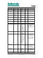
KNX1 Timing table
The table below shows the timing information for the module when changing between
different operating states. Timing symbol is according to figure 5 and 6.
[Table to be updated]
Symbol
tRX-TXD
Value
180 us
tTXD
Min 590 us
tTXD-IDLE
900 us
TRXD-CTS
20 us
tRXD-TX
960 us
TTX-IDLE
960 us
tOFF-IDLE
tRESET-IDLE
tSLEEP-IDLE
tCONFIG-PROMPT
TG-CONFIG
3.2 ms
3.0 ms
1.3 ms
60 us
1.1 ms
TG-CONFIG
TWAIT
TMEMORY-CONFIG
TCONFIG-IDLE
tTX
2010 Radiocrafts AS
Description / Note
Time from last byte is received from the air until first
character is sent on the UART
tTXD = # bytes received x 590 us/char (10 bits at 19.2 kBd
+ 70 us delay per character)
Time from last character is sent on the UART until
module is in IDLE mode (ready for RXD and RX)
Time from last character is received by the UART
(including any timeout) until CTS is activated
Time from last character is received by the UART
(including any timeout) until the module sends the first
byte on the air.
Time from last character is sent on the air until module is
in IDLE mode (ready for RXD and RX)
Time from 00h / CONFIG pin is set low until prompt (“>”)
Delay after channel-byte is sent until prompt (“>”).(For
other volatile memory commands there is no delay but
immediate prompt)
1.1 ms
Delay after new M-Bus mode-byte is sent until prompt
(“>”).(For other volatile memory commands there is no
delay but immediate prompt)
1.55 ms (B, K and M Delay from stop bit of the command byte to start bit of
command)
the prompt reply. See figure 5 for details.
24 us (all other
commands)
31 ms
In this period the internal flash (non-volatile memory) is
programmed. Do not reset, turn the module off, or allow
any power supply dips in this period as it may cause
permanent error in the Flash configuration memory.
After the last command parameter byte the host should
wait for the ‘>’ prompt before any further action is done
to ensure correct re-configuration.
1.1 ms
End of ‘X’ to IDLE
TX time for T1 mode when Length=1 on the UART.
3.6 ms
Preamble, sync, CRC and KNX address field added
internally. Depends on M-Bus mode (T, S, R) and L
KNX User Manual (rev. 0.30)
Page 14 of 22
KNX
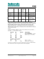
KNX1 Configuration Commands
A list of commands is shown in the table below. Commands must be sent as ASCII characters
or their corresponding binary value. All arguments must be sent as binary values to the
module (not as ASCII representation for hex or decimal).
Parameter
Bind
Command Argument in hex (decimal)
‘B’ – 0x42 Register number (1-64)
followed by 8 byte address
(NB: First two address bytes
must be FFh, 00h)
Note
Used to bind Transmitter
to Receiver. Data stored in
non-volatile memory.
KNX mode
‘G’ – 0x47
0x00-0x04 (0-4)
0: S2
3: S1
Data is stored in volatile
memory only.
Install
‘I’ – 0x49
0: Normal operation
2: Accept all messages
List binding
‘L’ – 0x4C
Register number (1-64)
Memory
configuration
‘M’ – 0x4D (Address, Data): see list of
parameters below.
0xFF exits memory
configuration.
Output power
‘P’ – 0x50
0x01-0x05 (1-5)
Quality
Indicator
‘Q’ – 0x51
Signal
Strength
(RSSI)
‘S’ – 0x53
Returns one byte indicating
the signal quality of the last
received packet
Returns one byte indicating
the signal strength of a
detected signal or a valid
packet.
Exit command
‘X’ – 0x58
(none)
Sleep mode
‘Z’ – 0x5A
(none)
Test mode 0
‘0’ – 0x30
(none)
Test mode 1
Test mode 2
‘1’ – 0x31
‘2’ – 0x32
(none)
(none)
Test mode 3
Test mode 4
‘3’ – 0x33
‘4’ – 0x34
(none)
(none)
Module responds with the
address stored in the
register (8 bytes)
Used to enter memory
configuration menu.
Parameters changed are
stored in non-volatile
memory.
Data is stored in volatile
memory only.
Based on bit errors
preamble and synch word
If a valid packet has been
received when in
configuration mode, it will
return the RSSI of the last
received packet.
Exit to normal operation
mode. All changes of
parameters take effect.
Exit sleep mode by
sending 0xFF on UART
RXD pin
List all configuration
memory parameters
TX carrier
TX modulated signal
PN9 sequence
TX off, RX mode
IDLE (TX off, RX off)
Note: ASCII characters are written as ‘X’, hexadecimal numbers are written like 0x00, and
decimal numbers are written like 10 throughout the text. A table of ASCII characters and their
respective hex and decimal values are found in the Appendix.
2010 Radiocrafts AS
KNX User Manual (rev. 0.30)
Page 15 of 22
KNX
Any invalid command will be ignored and the ‘>’ prompt will be re-sent.
If Test mode 1 or 2 is used, it is important to enter Test mode 3 before exiting the
configuration mode (‘X’) in order to ensure proper operation in normal mode.
Example:
To select RF channel 3, send the follow sequence after asserting the CONFIG line and the ‘>’
prompt is received:
Command
Enter
Hex
0x00
Response
‘>’
‘C’
0x43
‘>’
3
0x03
‘>’
[A new command could be issued here]
‘X’
0x58
(none)
Comment/Note
Or assert CONFIG pin
De-assert CONFIG after ‘>’ prompt
Wait for ‘>’ prompt
Module returns to IDLE state
Note that the CONFIG line must be de-asserted after the first ‘>’ prompt was received, but
before the ‘X’ command.
2010 Radiocrafts AS
KNX User Manual (rev. 0.30)
Page 16 of 22
KNX
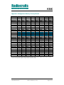
KNX1 Configuration Memory
The table below shows the complete list of configurable parameters stored in non-volatile
memory. These values can be changed using the ‘M’ command. All addresses and
arguments must be sent as binary values to the module (not as ASCII representation for hex
or decimal).
Parameter
Description
Address
hex
Argument
dec
Factory
setting
hex (dec)
Comment
Default RF
output power
0x01
1-5
0x05 (5)
See data sheet for output
power levels.
KNX_MODE
KNX mode
0x03
0: S2
3: S1
0x00 (0)
Use ‘G’ command to
change value in volatile
memory only
SLEEP_MODE
Sleep mode
0x04
0: Disable Sleep
1: Enable Sleep
after TX
2: Reserved
3: Enable Sleep
after TX and RX
5: As 1 with
sleep timeout
5: As 3 with
sleep timeout
0x00 (0)
When enabled the
module enter Sleep mode
after transmission (or
reception). Delay set by
RX_TIMEOUT
0:Disabled
1: Enabled
0x00 (0)
Radio configuration
RF_POWER
RSSI_MODE
Append RSSI
to received
data
PREAMBLE_
LENGTH
Short of long
preamble in S
mode only
Threshold
battery voltage
for alarm
BATTERY_
THRESHOLD
TIMEOUT
NETWORK_ROLE
Reserved
Reserved
SERIAL_NUMBER
SERIAL_NUMBER
SERIAL_NUMBER
SERIAL_NUMBER
2010 Radiocrafts AS
0x05
Radio packet configuration
0x0A
0x00 (0): Short
0x01 (1): Long
0x00 (0)
0x0B
85
0x00-0x3F
0: Disable
If enabled with sleep
timeout, the module goes
directly to Sleep after a
Reset, and to Sleep after
TIMEOUT when wakeup
from Sleep or exit Config
mode.
When enabled the RSSI
value is appended to the
received data
Preamble (header)
length. Use long for KNX
Ready.
Step size is 30 mV/step,
85 corresponds to 2.5 V.
The function is disabled if
set to 0.
IF SLEEP_MODE=3 the
same timeout is used to
auto sleep slaves.
Time before
0x10
<1-254>
0x7C
modem clear
0x01 (1): 32 ms
buffer without
0x02 (2): 48 ms
transmitting if
0x03 (3): 64 ms
Buffer size <
0x7C (124): 2 s
Modem transmit without
Length byte
0xF9 (249): 4 s
timeout when
(first byte).
Buffer size = length byte.
Medium access, addressing and network management
0x12
0x00 (0):
0x00 (0)
Transmitter/Rece
iver
0x01 (1):
Reserved
0x10 (2):
Reserved
0x19
0xFF
(255)
0x1A
0x00 (0)
Serial number, 0x1B
0x00-0xFF
0x12 (18)
first byte
(0-255)
Serial number, 0x1C
0x00-0xFF
0x34 (52)
second byte
(0-255)
Serial number, 0x1D
0x00-0xFF
0x56 (86)
third byte
(0-255)
Serial number, 0x1E
0x00-0xFF
0x78
KNX User Manual (rev. 0.30)
Page 17 of 22
KNX
SERIAL_NUMBER
SERIAL_NUMBER
DOMAIN_ADDRESS
DOMAIN_ADDRESS
DOMAIN_ADDRESS
DOMAIN_ADDRESS
DOMAIN_ADDRESS
DOMAIN_ADDRESS
UART_BAUD_RATE
UART_FLOW_CTRL
DATA_INTERFACE
FREQ_CAL
fourth byte
(0-255)
(120)
Serial number, 0x1F
0x00-0xFF
0x90
fifth byte
(0-255)
(144)
Serial number, 0x20
0x00-0xFF
0x00 (0)
sixth byte
(0-255)
Domain
0x21
0x00-0xFF
0x01 (1)
Address, first
(0-255)
byte
Domain
0x22
0x00-0xFF
0x02 (2)
Address,
(0-255)
second byte
Domain
0x23
0x00-0xFF
0x03 (3)
Address, third
(0-255)
byte
Domain
0x24
0x00-0xFF
0x04 (4)
Address, fourth
(0-255)
byte
Domain
0x25
0x00-0xFF
0x05 (5)
Address, fifth
(0-255)
byte
Domain
0x26
0x00-0xFF
0x06 (6)
Address, sixth
(0-255)
byte
Data and configuration interface, UART Serial Port
Baud rate
0x30
0x00: Not used
0x05 (5)
0x01: 2400
0x02: 4800
0x03: 9600
0x04. 14400
0x05: 19200
0x06: 28800
0x07: 38400
0x08: 57600
0x09: 76800
0x0A: 115200
0x0B: 230400
UART flow
0x35
0: None
0x00 (0)
control
1:CTS only
3:CTS/RTS
4:RXTX(RS485)
0x00 (0)
Data interface
0x36
0x00: KNX
packet with ID
and address
0x01: Application
data only
0x02: Reserved
0x03: Reserved
0x04: Add
start/stop byte
0x08: Add CRC
0x0C: Add
start/stop byte
and CRC
0x10: TX
complete
(00:3Fh)
0x39
Different
for each
module.
LED_CONTROL
0x3A
INSTALL_MODE
0x3D
2010 Radiocrafts AS
0: Disabled
1: RX/TX
indicator
2: UART/RF
IDLE indicator
0: Normal mode
0x00 (0)
2
KNX User Manual (rev. 0.30)
BE CAREFUL IF
CHANGING AS HOST
MAY LOOSE CONTACT
WITH MODULE!
Does not take effect until
module is re-booted /
reset.
Sets receiver data format.
First byte is always
packet length (except
when using start byte)
0x10 can be combined
with the other settings by
using 0x11 – 0x1C
Found in factory and
used by the module to
minimise the total
frequency tolerance. For
firmware upgrade, read
back the value and write
it back after the upgrade.
Use to enable
LED0/LED1 for RX/TX
packet indication or
UART/RF IDLE mode
indicator.
Page 18 of 22
KNX
PART_NUMBER
0x600x6B
0x6D0x72
0x740x77
0xC00xC7
HW_REV_NO
FW_REV_NO
MODULE_SERIAL_
NUMBER
Exit from memory
configuration
0xFF
(accept installed
transmitters only)
1: Reserved
2: Filter off
(accept all
messages)
RCxxxxKNX1
x.yz
x.yz
All 0x00
No argument
should be sent
x, y and z; Any number
0d-9d
x, y and z; Any number
0d-9d
8 bytes reserved for serial
number for traceability. Is
programmed by
Radiocrafts during test.
To exit from command
mode the ‘X’ command
must be sent after ‘>’ is
received.
To make permanent changes to default values and other parameters, the Memory
Configuration command ‘M’ is used. This command should be followed by pairs of byte being
the memory address and the new value to be stored at that address. In order to exit the
Memory Configuration mode, the ‘address’ 0xFF must be sent, but without any data
argument. Then wait for the ‘>’ prompt while the internal memory is re-programmed (See
Timing Information for typical delay). To completely exit from command mode, the normal exit
command ‘X’ must be sent.
Example:
To change the DOMAIN_ADDRESS (at address 0x21 and 0x26) and set it to (100,200, …)
(0x64,0xC8, …), send the following sequence:
Command
Enter
Hex
0x00
Response
‘>’
‘M’
0x4D
‘>’
0x21
0x21
(none)
100
0x64
(none)
0x22
0x22
(none)
200
0xC8
(none)
[new address could be sent here]
[new value could be sent here]
0xFF
0xFF
‘>’
‘X’
0x58
(none)
Comment/Note
Or assert CONFIG pin
De-assert CONFIG after ‘>’ prompt
Module ready to receive address
Wait for ‘>’ prompt
Module returns to IDLE state
Test mode 0 (‘0’ command) can be used to list all parameters stored in non-volatile memory.
This command can be used to verify and check the module configuration.
2010 Radiocrafts AS
KNX User Manual (rev. 0.30)
Page 19 of 22
KNX
Appendix: Configuration Memory Factory Default
Address
0x00-0x07
0x08-0x0F
0x10-0x17
0x18-0x1F
0x20-0x27
0x28-0x2F
0x30-0x37
0x38-0x3F
0x40-0x47
0x48-0x4F
0x50-0x57
0x58-0x5F
0x60-0x67
0x68-0x6F
0x70-0x77
0x78-0x7F
0x80-0x87
0x88-0x8F
0x90-0x97
0x98-0x9F
0xA0-0xA7
0xA8-0xAF
0xB0-0xB7
0xB8-0xBF
0xC0-0xC7
0xC8-0xCF
0xD0-0xD7
0xD8-0xDF
0xE0-0xE7
0xE8-0xEF
0xF0-0xF7
0xF8-0xFF
KNX1 factory default Values
0x0B
0x05
0x02
0x00
0x05
0x3C
0x00
0x55
0x7C
0x00
0x00
0x01
0x00
0xFF
0x00
0x12
0x00
0x01
0x02
0x03
0xFF
0x08
0x00
0x00
0x05
0x08
0x00
0x01
0x2B
0x00
0x00
0x44
0xFF
0xFF
0xFF
0xFF
0xFF
0xFF
0xFF
0xFF
0x00
0x00
0x00
0x00
0x00
0x00
0x00
0x00
0x00
0x52
0x43
0x31
0x4B
0x4E
0x58
0x31
0x30
0x2C
0x30
0x42
0xFF
0xFF
0xFF
0xFF
0xFF
0xFF
0xFF
0xFF
0xFF
0xFF
0xFF
0xFF
0xFF
0xFF
0xFF
0xFF
0xFF
0xFF
0xFF
0xFF
0xFF
0xFF
0xFF
0xFF
0xFF
0xFF
0xFF
0xFF
0xFF
0xFF
0xFF
0xFF
0xFF
0xFF
0xFF
0xFF
0xFF
0xFF
0xFF
0xFF
0xFF
0xFF
0xFF
0xFF
0xFF
0xFF
0xFF
0xFF
0xFF
0xFF
0xFF
0xFF
0xFF
0xFF
0xFF
0xFF
0xFF
0xFF
0xFF
0xFF
0xFF
0xFF
0xFF
0xFF
0xFF
0xFF
0xFF
0xFF
0x00
0x00
0x00
0x34
0x04
0x00
0x05
0x06
0xFF
0xFF
0x00
0x00
0x31
0x2C
0x30
0xFF
0xFF
0xFF
0xFF
0xFF
0xFF
0xFF
0xFF
0xFF
0xFF
0xFF
0xFF
0xFF
0xFF
0xFF
0xFF
0xFF
0x00
0x00
0x00
0x56
0x05
0x00
0x00
0x02
0Xff
0xFF
0x00
0x00
0x38
0x32
0x31
0xFF
0xFF
0xFF
0xFF
0xFF
0xFF
0xFF
0xFF
0xFF
0xFF
0xFF
0xFF
0xFF
0xFF
0xFF
0xFF
0xFF
0x64
0x80
0x17
0x78
0x06
0x00
0x00
0x00
0xFF
0xFF
0x00
0x00
0x30
0x2E
0x20
0xFF
0xFF
0xFF
0xFF
0xFF
0xFF
0xFF
0xFF
0xFF
0xFF
0xFF
0xFF
0xFF
0xFF
0xFF
0xFF
0xFF
0x00
0x80
0x00
0x90
0x04
0x00
0x01
0x00
0xFF
0xFF
0x00
0x00
0x2D
0x30
0x00
0xFF
0xFF
0xFF
0xFF
0xFF
0xFF
0xFF
0xFF
0xFF
0xFF
0xFF
0xFF
0xFF
0xFF
0xFF
0xFF
0xFF
Grey: Reserved (do not change).
Blue: Reserved for Module part number and version information (do not change). Typical values shown, the actual
content of memory in this depends on part number and version number
2010 Radiocrafts AS
KNX User Manual (rev. 0.30)
Page 20 of 22
KNX
Appendix: ASCII Table
HEX
0
1
2
3
4
5
6
7
8
9
0A
0B
0C
0D
0E
0F
10
11
12
13
14
15
16
17
18
19
1A
1B
1C
1D
1E
1F
20
21
22
23
24
25
26
27
28
29
2A
2B
2C
DEC
0
1
2
3
4
5
6
7
8
9
10
11
12
13
14
15
16
17
18
19
20
21
22
23
24
25
26
27
28
29
30
31
32
33
34
35
36
37
38
39
40
41
42
43
44
CHR
NUL
SOH
STX
ETX
EOT
ENQ
ACK
BEL
BS
HT
LF
VT
FF
CR
SO
SI
DLE
DC1
DC2
DC3
DC4
NAK
SYN
ETB
CAN
EM
SUB
ESC
FS
GS
RS
US
SP
!
"
#
$
%
&
'
(
)
*
+
,
2D
2E
2F
30
31
32
33
34
35
36
37
38
39
3A
3B
3C
3D
45
46
47
48
49
50
51
52
53
54
55
56
57
58
59
60
61
HEX
40
41
42
43
44
45
46
47
48
49
4A
4B
4C
4D
4E
4F
50
51
52
53
54
55
56
57
58
59
5A
5B
5C
5D
5E
5F
60
61
62
63
64
65
66
67
68
69
6A
6B
6C
DEC
64
65
66
67
68
69
70
71
72
73
74
75
76
77
78
79
80
81
82
83
84
85
86
87
88
89
90
91
92
93
94
95
96
97
98
99
100
101
102
103
104
105
106
107
108
CHR
@
A
B
C
D
E
F
G
H
I
J
K
L
M
N
O
P
Q
R
S
T
U
V
W
X
Y
Z
[
\
]
^
_
`
a
b
c
d
e
f
g
h
i
j
k
l
.
/
0
1
2
3
4
5
6
7
8
9
:
;
<
=
6D
6E
6F
70
71
72
73
74
75
76
77
78
79
7A
7B
7C
7D
109
110
111
112
113
114
115
116
117
118
119
120
121
122
123
124
125
m
n
o
p
q
r
s
t
u
v
w
x
y
z
{
|
}
3E
3F
62
>
7E
126
~
63
?
7F
127
DEL
2010 Radiocrafts AS
−
CTRL
^@
^A
^B
^C
^D
^E
^F
^G
^H
^I
^J
^K
^L
^M
^N
^O
^P
^Q
^R
^S
^T
^U
^V
^W
^X
^Y
^Z
KNX User Manual (rev. 0.30)
Page 21 of 22
KNX
Document Revision History
Document Revision
1.0
First release
Changes
Disclaimer
Radiocrafts AS believes the information contained herein is correct and accurate at the time of this printing. However,
Radiocrafts AS reserves the right to make changes to this product without notice. Radiocrafts AS does not assume
any responsibility for the use of the described product; neither does it convey any license under its patent rights, or
the rights of others. The latest updates are available at the Radiocrafts website or by contacting Radiocrafts directly.
As far as possible, major changes of product specifications and functionality, will be stated in product specific Errata
Notes published at the Radiocrafts website. Customers are encouraged to check regularly for the most recent
updates on products and support tools.
Trademarks
All other trademarks, registered trademarks and product names are the sole property of their respective owners.
Life Support Policy
This Radiocrafts product is not designed for use in life support appliances, devices, or other systems where
malfunction can reasonably be expected to result in significant personal injury to the user, or as a critical component
in any life support device or system whose failure to perform can be reasonably expected to cause the failure of the
life support device or system, or to affect its safety or effectiveness. Radiocrafts AS customers using or selling these
products for use in such applications do so at their own risk and agree to fully indemnify Radiocrafts AS for any
damages resulting from any improper use or sale.
© 2010, Radiocrafts AS. All rights reserved.
Contact Information
Web site: www.radiocrafts.com
Address:
Radiocrafts AS
Sandakerveien 64
NO-0484 OSLO
NORWAY
Tel: +47 4000 5195
Fax: +47 22 71 29 15
E-mails: [email protected]
[email protected]
[email protected]
Radiocrafts is a member of the KNX association, and will work closely with the association to
enable manufacturers of wired KNX products to develop wireless products compliant with the
KNX-RF standard. You can also find more information on the KNX association web site:
www.knx.org
2010 Radiocrafts AS
KNX User Manual (rev. 0.30)
Page 22 of 22