1
Operating Instructions
from program version:
DMP 96 E - Z - 2P/3P
DMP 96 E - Y - 2P/3P
DMP 48 ES - Z - 2P/3P
DMP 48 ES - Y - 2P/3P
310M0
DMP 48 EW - Z - 2P/3P
DMP 48 EW - Y - 2P/3P
with configurable input
as Single channel controller
Z:
Y:
2P:
3P:
Sensor Pt 100, Thermocouple, Standard signal
NTC UUA 2.25 K, NTC UUA 10 K, PTC KTY 10.6,
Potentiometer 1kΩ
Ω ...100kΩ
Ω
DMP 96 E
Two point controller, Continuous controller
Three-point controller, Three-point stepping controller
DMP 48 EW
DMP 48 ES
K1
K2
A
B
P
DMP 96 E
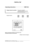
Operating and display elements
Actual value display in operating mode,
parameter display in input mode
Nominal value display in operating mode,
parameter value in input mode
LED is lit if logic output is active,
LED flashes if logic output is locked
LED is lit if logic input is activated
LED is lit if output K 1 is active,
LED flashes if output K 1 is locked
LED is lit if output K 2 is active,
LED flashes if output K 2 is locked
Switching key controller / manual actuator
Jump to input level and operating level, confirmation key,
keying through the parameters on one level
Increasing code value, parameter value
Reducing code value, parameter value
The display elements K 1, K 2 and A in locked condition
Limit contact with locking, break contact
Limit contact with locking, make contact
LED flashing (tact ratio approx. 1/5 LED on / LED OFF)
LED flashing (tact ratio approx. 5/1 LED on / LED OFF)
The operating structure
Read and observe these operating instructions before commissioning the unit into operation. Read and observe the
added pages " Safety notes and Installation notes ".
In operating mode
Display
press for short time
P
("Cod.u" = OFF)
Operating level
(nominal value setting)
SEt.1
XXX
Configuration of the unit
Configuration and programming of the unit
P
press (approx.
3 seconds) until:
P
Parameter setting at the various levels
current value:
after 10 steps
after 10 steps
+1
+10
+100
current value:
after 10 steps
after 10 steps
-1
-10
-100
enter
restart timeout (extend) during input
Display
CodE
100
Display
only when function
is released
adjust until:
CodE
1155
P
Definition level: define the type of
input and the type of unit
CodE
855
P
Configuration level: configurate the
controller function, the limiting values
CodE
55
P
CodE
955
P
Parameter level: adapt the unit to
the controller system
Range limit setting level:
set the range limits and carry out
the lead balancing
CodE
355
P
CodE
655
P
Linearization level: to program the
linearity graph
CodE
755
P
Error definition level: determine
the character of the outputs in case
of an error
CodE
925
P
CodE
109
P
Nominal value input level: nominal
value setting via code input ("Cod.u"
= on)
Limit contact unlocking level: for
unlocking the limiting values
CodE
101
P
Error acknowledging level: to acknowledge the error message "Err.3"
CodE
111
P
Self-tuning level: starting and
discontinuing of the tuning
After accepting the last parameter, jump back into operating mode.
If within approx. 30 seconds (timeout) no key is activated, automatic jump back
to operating mode. The possibly altered value is not accepted. With the star key
the timeout can be restarted (extended).
If an incorrect code number is accepted for jumping to a level, then "FALS" appears on the display. You have to wait for timeout and for the jump back to operating mode before you can input a new code number (approx. 30 seconds). After
this a new code input can be carried out.
Dold GmbH . Blumenstr. 33 . 70736 Fellbach . Tel.: 0711 95152-0 FAX 0711 95152-19 . www.dold-regler.de . [email protected]
1
DOLD GmbH
Operating instructions
Parameters of the definition level
(code 1155)
With standard signal input and potentiometer input the range
limits must be set at the range limit level (code 955).
Type of input
01: Sensor Pt 100
08: Current 0...20 mA
02: Fe-CuNi Type L
09: Current 4...20 mA
03: Fe-CuNi Type J
10: Voltage 0...50 mV DC
04: NiCr-Ni Type K
20: Sensor NTC UUA 10 K
05: PtRh-Pt Type S
21: Sensor NTC UUA 2.25 K
06: Voltage 0...10 V DC
22: Sensor PTC KTY 10.6
07: Voltage 2...10 V DC
23: Potentiometer 1kΩ...100kΩ
Unit type
01: Two point controller with 2 limit contacts:
controller output
output K 1
limit contact 1
output K 2
limit contact 2
logic output
actual value, setpoint
value, fixed value
analogue output
02: Two point controller with 2 limit contacts:
controller output
logic output
limit contact 1
output K 1
limit contact 2
output K 2
actual value, setpoint
value, fixed value
analogue output
03: Continuous PID-controller / Two point controller with hysteresis setting (for SSR) and 3 limit contacts:
controller output
analogue output
limit contact 1
output K 1
limit contact 2
output K 2
limit contact 3
logic output
04: Three-point controller with 1 limit contact:
controller output
output K 1 heating
controller output
output K 2 cooling
limit contact 1
logic output
actual value, setpoint
value, fixed value
analogue output
05: Three-point controller with 1 limit contact:
controller output
output K 1 heating
controller output
logic output cooling
limit contact 1
output K 2
actual value, setpoint
value, fixed value
analogue output
06: Three-point controller with 1 limit contact:
controller output
logic output heating
controller output
output K 1 cooling
limit contact 1
output K 2
actual value, setpoint
value, fixed value
analogue output
07: Three-point controller with 2 limit contacts:
controller output
analogue output heating
controller output
output K 1 cooling
limit contact 1
output K 2
limit contact 2
logic output
08: Three-point stepping controller with PD character and
1 limit contact:
controller output
K 1 heating resp. valve "open"
controller output
K 2 cooling resp. valve "close"
limit contact 1
logic output
actual value, setpoint
value, fixed value
analogue output
Display /
Works
setting
"dEFn"
"inPt" /
01
(unit of
version Z)
20
(unit of
version Y)
"tYPE" /
01
m0e310q.doc
Function: Limit contact absolute
00, 07: output no function
01: make contact referenced to increasing temperature
04: break contact referenced to increasing temperature
08: as function 01 with locking
11: as function 04 with locking
Function: Limit contact following to the nominal value
00, 07: output no function
02: make contact referenced to increasing temperature
05: break contact referenced to increasing temperature
09: as function 02 with locking
12: as function 05 with locking
Function: Limiting comparator
00, 07: output no function
03: limiting comparator in the approval range closed
06: limiting comparator in the approval range open
10: as function 03 with locking
13: as function 06 with locking
Please note:
08...13: Unlocking possibilities: with logic input (with parameter setting "Con.L" = 04) or via level code 109.
With configuration "Li.1", "Li.2", "Li.L" = 08...13 (Limit contact
with locking) and "Con.L" ≠ 04 the appropriate limit contact remains locked until power switch off.
Automatic function (controller / manual actuator);
only with function Two point controller / Continuous controller with PID character
("TYPE" = 01, 02, 03; "Ctr.1", "Ctr.L", "Ctr.A" = 02 or 04)
on: controller
OFF: manual actuator
switching between controller / manual actuator via
(and
Parameters of the parameter level
(Code 55)
The parameters appears independent of the unit type "tYPE"
(code 1155). After changing configuration or re-configuration the
controller character and the switching function of the limit contacts, the appropriate parameters must be set at the parameter
level (code 55) or be adapted to the controlled system.
Two point controller / Continuous controller
Configuration of the controller output
"Ctr.1" / 04
Output K 1
"Ctr.L" / 04
Logic output for triggering a SSR
"Ctr.A" / 04
Analogue output
01: Two point controller cooling with hysteresis setting to
higher temperature
02: Two point controller cooling with PID character
03: Two point controller heating with hysteresis setting to lower
temperature
04: Two point controller heating with PID character
The analogue output can, configured as cooling or heating controller with hysteresis setting (parameter "Ctr.A" = 01 or 03), also
be used as logic output for triggering a SSR.
Three point controller - configuration of the controller outputs
"CtP.1" / 02
Output K 1
"CtP.2" / 02
Output K 2
"CtP.L" / 02
Logic output
"CtP.A" / 02
Analogue output
01: Three point controller with hysteresis setting
02: Three point controller with PID character
The analogue output can, configured as controller output with
2
hysteresis setting (parameter "Ctp.A" = 01), also be used as
logic output for triggering a SSR.
Three-point stepping controller - configuration of the controller outputs
Outputs K 1 and K 2 are assigned to the controller function. The
configuration of the outputs is not necessary.
Configuration of the limit contacts,
(only for outputs without controller function)
Output K 1
Output K 2
Logic output
-
"Li.1" / 00
"Li.2" / 00
"Li.L" / 00
"Auto" /
on
reverse)
Display /
Works
setting
"CFG"
Parameters of the configuration level
(Code 855)
Display /
Works
setting
Parameters of the configuration level
(Code 855)
The parameters appears independent of the configured function
in code level 855).
K 1 Controller output with hysteresis
Two point controller ("tYPE" = 01; "Ctr.1" = 01, 03)
Three point controller ("tYPE" = 04, 05, 06, 07; "CtP.1" = 01)
hysteresis
K 1 Controller output with PID character
Three point controller ("tYPE" = 04, 05, 06, 07; "CtP.1" = 02)
death band
K 1 Controller output with PID character
Two point controller("tYPE" = 01; "Ctr.1" = 02, 04)
Three point controller ("tYPE" = 04, 05, 06, 07; "CtP.1" = 02)
proportional band
integral time (setting 0 = portion 0)
derivative time (setting 0 = portion 0)
cycle time
Set the PID return parameter according to your experiences or
your measurements, or start a self-tuning.
K 1 and K 2 Controller outputs
Three-point stepping controller ("tYPE" = 08)
proportional band
integral time (setting 0 = portion 0)
derivative time (setting 0 = portion 0)
cycle time
motor running time
Set the PID return parameter according to your experiences or
your measurements, or start a self-tuning.
K 1 Limit contact absolute ("tYPE" = 02, 03; "Li.1" = 01, 04, 08, 11)
limit absolute
hysteresis
K 1 Limit contact following to the nominal value
("tYPE" = 02, 03; "Li.1" = 02, 05, 09, 12)
limit relative
hysteresis
K 1 Limiting comparator ("tYPE" = 02, 03; "Li.1" = 03, 06, 10, 13)
symmetric spreading (hysteresis 0.5°C or 5 Digit fix)
K 2 Controller output with hysteresis
Three point controller ("tYPE" = 04; "CtP.2" = 01)
hysteresis
Number of pages: 4
Date: 01.02.2007
Display /
Works
setting
"PArA"
"HY.1" /
1.0°C /
10 Digit
"db.1" /
0.0°C /
0 Digit
"Pb.1" / 5.0°C
"ti.1" / 250 s
"td.1" / 50 s
"CY.1" / 30 s
"Pb.1" / 5.0°C
"ti.1" / 250 s
"td.1" / 50 s
"CY.1" / 30 s
"run" / 60 s
"LA.1" / 0°C
"HY.1"/1.0°C
"Lr.1" / 0°C
"HY.1"/1.0°C
"bd.1" /
5.0°C/50 Dig.
"HY.2" /
1.0°C/10 Digit
DMP 96 E / DMP 48 ES / DMP 48 EW
Operating instructions
DOLD GmbH
Parameters of the parameter level
(Code 55)
K 2 Controller output with PID character
Three point controller ("tYPE" = 04; "CtP.2" = 01)
death band
K 2 Controller output with PID character
Three point controller ("tYPE" = 04; "CtP.2" = 02)
proportional band
integral time (setting 0 = portion 0)
derivative time (setting 0 = portion 0)
cycle time
K 2 Limit contact absolute
("tYPE" = 01, 02, 03, 05, 06, 07; "Li.2" = 01, 04, 08, 11)
limit absolute
hysteresis
K 2 Limit contact following to the nominal value
("tYPE" = 01, 02, 03, 05, 06, 07; "Li.2" = 02, 05, 09, 12)
limit relative
hysteresis
K 2 Limiting comparator
("tYPE" = 01, 02, 03, 05, 06, 07; "Li.2" = 03, 06, 10, 13)
symmetric spreading (hysteresis 0.5°C or 5 Digit fix)
Logic output as controller output with hysteresis
Two point controller ("tYPE" = 02; "Ctr.L" = 01, 03)
Three point controller ("tYPE" = 05, 06; "CtP.L" = 01); hysteresis
Logic output as controller output with PID character
Three point controller ("tYPE" = 05, 06; "CtP.L" = 01);
death band
Logic output as controller output with PID character
Two point controller ("tYPE" = 02; "Ctr" = 02, 04)
Three point controller ("tYPE" = 05, 06; "CtP.L" = 02)
proportional band
integral time (setting 0 = portion 0)
derivative time (setting 0 = portion 0)
cycle time
Logic output as Limit contact absolute
("tYPE" = 01, 03, 04, 07, 08; "Li.L" = 01, 04, 08, 11)
limit absolute
hysteresis
Logic output as Limit contact following to the nominal value
("tYPE" = 01, 03, 04, 07, 08; "Li.L" = 02, 05, 09, 12)
limit relative
hysteresis
Logic output as Limiting comparator
("tYPE" = 01, 03, 04, 07, 08; "Li.L" = 03, 06, 10, 13)
symmetric spreading (hysteresis 0.5°C or 5 Digit fix))
Analogue output with hysteresis
Two point controller ("tYPE" = 03; "Ctr.A" = 01, 03)
Three point controller ("tYPE" = 07; "CtP.A" = 01); hysteresis
Analogue output
Three point controller ("tYPE" = 07; "CtP.A" = 01); death band
Analogue output with PID character
Continuous controller ("tYPE" = 03; "Ctr.A" = 02, 04)
Three point controller ("tYPE" = 07; "CtP.A" = 02)
proportional band
integral time (setting 0 = portion 0)
derivative time (setting 0 = portion 0)
Parameters of the range limit setting level
(Code 955)
Display /
Works
setting
"db.2" /
0.0°C /
0 Digit
Number of pages: 4
Display /
Works
setting
"StA.A" /
0%
Regulation ratio in % with fixed value,
(fixed value of current or fixed value of voltage)
0...100% refers to size of output 0..20 mA, 0..1 V DC, 0..2 V DC,
0...5 V DC, 0...10 V DC (according to order)
Output value of the last regulation ratio after stopped regu"StP.A" /
on
lation (only with Two point controller / Continuous controller, "TYPE" = 03)
on: output value of the regulation ratio = 0%
OFF: output value of the last regulation ratio
"Con.L" /
Configuration Logic input (the contact must be opened or closed
00
for a minimum of 0.5 seconds, so that the required function occurs).
00: logic input no function
01: switching nominal value burden / regulation ratio
contact open
nominal value 1 / regulation ratio 1
contact closed
nominal value 2 / regulation ratio 2
02: stop function
contact closed
controller output deactivated and lower
display dark
03: programming disabled
contact closed
programming enabled
contact closed
programming disabled
04: unlocking limit contacts ("Li.X" = 08...13)
Nominal value setting
"Cod.u" /
OFF
on: nominal value setting via nominal value input level (Code 925)
OFF: nominal value setting via operating level
Nominal value range start
"rALo" / 0°C
Nominal value range end
"rAhi" /
600°C /
With configuration "rALo" = "rAhi" nominal value setting at the
operating level or at the nominal value setting level is not possi- 9999 Digit
ble. With configuration "rAhi" < "rALo" switching between the set
values at the operating level or at the nominal value setting level
or
.
is possible with the buttons
"Pb.2" / 5.0°C
"ti.2" / 250 s
"td.2" / 50 s
"CY.2" / 30 s
"LA.2" / 0°C
"HY.2"/1.0°C
"Lr.2" / 0°C
"HY.2"/1.0°C
"bd.2" /
5.0°C /
50 Digit
"HY.L" /
1.0°C /
10 Digit
"db.L" /
0.0°C/0 Digit
"Pb.L"/5.0°C
"ti.L" / 250 s
"td.L" / 50 s
"CY.L" / 30 s
Range start output analogues to the actual value or to the
setpoint value ("tYPE" = 01, 02, 04, 05, 06, 08)
starting value for 0 mA / 0 V resp. 4 mA / 0,2 V / 0,4 V / 1 V / 2 V DC
Range end output analogues to the actual value or to the
setpoint value ("tYPE" = 01, 02, 04, 05, 06, 08)
range end for 20 mA DC / 1 V DC / 2 V DC / 5 V DC / 10 V DC
Display resolution (depend on type of input "inPt")
Pt 100, Thermocouple, NTC, PTC ("inPt" = 01...05; 20...22):
00: resolution
1°C
01:
resolution 0.1°C
Standard signal, Potentiometer ("inPt" = 06...10; 23):
00: resolution
1
02:
resolution
0.01
01: resolution
0.1
03:
resolution 0.001
Linearization
on: using the programmable linearity graph
OFF: using the internal linearity graph
Linearization range start = 0%: -999.9...9999 Digit
Linearization range end = 100%: -999.9...9999 Digit
"LA.L" / 0°C
"HY.L"/1.0°C
"Lr.L" / 0°C
"HY.L"/1.0°C
"bd.L" /
5.0°C /
50 Digit
"HY.A" /
1.0°C /
10 Digit
"db.A" /
0.0°C/0 Digit
"AnLo" /
0°C /
0 Digit
"Anhi" /
100°C /
1000 Digit
"dECP" /
00
"Lin.F" /
OFF
"LLo"/0 Digit
"Lhi"/1000 D.
Parameters of the linearization level (Code 655)
"Pb.A"/5.0°C
"ti.A" / 250 s
"td.A" / 50 s
X-value of pair 1
A.01
"A.01" / Y-value of pair 1
b.01
"b.01" / X-value of pair 2
A.02
"A.02" / Y-value of pair 2
b.02
"b.02" / X-value of the last pair
A.n
"A.XX" / n: X-value of the last pair (n = maximum 32)
Y-value of the last pair
b.n
"b.XX" / n: Y-value of the last pair (n = maximum 32)
Identification the end of the linearization (A.n+1),
"A.XX"
input: -1
enter
Please note!
"A.XX": X-value of the linearization function. Fixing
the several ranges of the linearity graph.
"A.XX" - values must be set increased:
"A.01" < "A.02" < ... < "A.n" !
"b.XX": Y- value of the linearization function.
Display /
Works
setting
"rAnG"
After any change of configuration or re-configuration of the
nominal value range, the nominal value settings must be monitored at the operating level or at the nominal value setting level
(Code 925) and adapted to the nominal value range. The parameter settings are dependant on the input definitions.
Lead balancing or zero point correction
"Corr" / 0°C
Evaluation of the internal temperature compensation
"Co.Co" /
on
on: evaluation of the internal temperature compensation
OFF: no evaluation of the internal temperature compensation
Display range start ("inPt" = 06...10; 23)
"inLo"/0 Digit
"inhi" /
Display range end ("inPt" = 06...10; 23)
9999 Digit
configuration "inLo" > "inhi" with inverted input signal
Note: actual value < -999 Digit: "-UFL" is displayed
actual value > 9999 Digit: "OFL" is displayed
"con.A" /
Configuration analogue output (output size according to order)
01
01: 0..20 mA; 0...1 V DC; 0...2 V DC; 0...5 V DC; 0...10 V DC
02: 4..20 mA; 0,2..1 V DC; 0,4..2 V DC; 1..5 V DC; 2..10 V DC
03: 4..20 mA; 0,2..1 V DC; 0,4..2 V DC; 1..5 V DC; 2..10 V DC
Extension to function 02: the output value will become
lower as the minimum size of output (according to order)
0...20 mA, 0...1 V DC, 0...2 V DC, 0...5 V DC, 0...10 V DC).
analogue output
"SEL.A" /
01
01: output analogues to the actual value
02: output analogues to the setpoint value
03: fixed value of current or fixed value of voltage
Inverse operation of the continuous controller
"in.A" /
OFF
on: inverse operation of the continuous controller
OFF: direct operation of the continuous controller
m0e310q.doc
Parameters of the range limit setting level
(Code 955)
Parameters of the error definition level (Code 755)
Incorrect error allocation at the outputs can, in the event of an
"FAUL"
error, cause substantial damage to persons and property!
"FLt.1"/OFF
Error allocation output K 1, K 2, logic output
"FLt.2"/OFF
on: output active in event of an error
"FLt.L"/OFF
OFF: output inactive in event of an error
Locked limit contacts are unlocked in the event of an error!
Error allocation analogue output; output signal in event of an
"FLt.A" /
0.0 %
error in %, refer to size of output 0..20 mA, 0...1 V DC, 0...2 V
DC, 0...5 V DC, 0...10 V DC (according to order)
The nominal value input level (Code 925)
Setting the nominal value is only possible with code input, if parameter "Cod.u" is on at the range limit level.
Nominal value 1
Nominal value 2 (appears only with configuration "Con.L" = 01)
Date: 01.02.2007
DMP 96 E / DMP 48 ES / DMP 48 EW
"SEt.1"/0°C
"SEt.2"/0°C
3
DOLD GmbH
Operating instructions
Display /
Works
setting
"SEt.1"/0°C
"SEt.2"/0°C
Nominal value setting via operating level
Nominal value 1
Nominal value 2 (appears only with configuration "Con.L" = 01)
Regulation ratios
Manual actuator only with function Two point controller /
Continuous controller ("TYPE = 01, 02, 03). The unit can, configured as PID controller, also be used as manual actuator. If the
parameters "Ctr.1" , "Ctr.L" or "Ctr.A" are set to 02 or 04 and "Auto“
is set to "OFF“), then switching from controller operation to manual
actuator operation (and reverse) is possible with button
.
Regulation ratio 1 (appears only with configuration "Ctr.1" ,
"Ctr.L" or "Ctr.A" = 02 or 04 and "Auto" = OFF)
Regulation ratio 2 (appears only with configuration "Ctr.1" ,
"Ctr.L" or "Ctr.A" = 02 or 04; "Auto" = OFF and "Con.L" = 01)
"-Y-1" /
0%
"-Y-2" /
0%
The limit contact unlocking level (Code 109)
At this level the limit contacts can be unlocked by setting code 109.
The error acknowledging level (Code 101)
At this level the error message "Err.3" can be acknowledged by setting code 101.
Please note! "Error messages" : Err.3.
Adapting the PID controller automatically to the controlled system - the
self-tuning
− set nominal value and tune the controller
− let controller stabilise and operate the plant
− evaluate controller efficiency and correct controller parameters if necessary.
The self-tuning works according to the setting rules of Ziegler-Nichols. With controlled systems of a higher order and with controlled systems with greater dead
times and delay times, it does not always lead to optimal results. The controller
parameters must be corrected only with greater actual value fluctuations after
self-tuning. The tuning on the heating side is only possible, if heat is removed
from the system, so that the temperature falls again below the nominal value. The
tuning on the cooling side is only possible, if the system develops its own heat,
so that the temperature after cooling rises above the nominal value by itself.
To correct the controller parameters yourself, you will need indepth knowledge of regulating methods!
Lifetime of relays independent of cycle time!
The self-tuning level (code 111)
Display
Start up
Discontinuation
Opti / on
Opti / OFF
During self-tuning extreme conditions can occur in the plant.
The self-tuning procedure must be monitored continuously.
After self-tuning the parameter "CY.X" at the parameter level
must be checked. Lifetime of relays independent of cycle time!
Inspection of the tuning
The inspection of the tuning is important for the correct setting of the process. The
inspection of the settings can be carried out by observation of the controller procedure or by recording the controller curve with a suitable recording apparatus.
Lifetime of the relay
Period per switch- Period, after which the 106 switching cycles are
ing cycle
reached (8 hour/day operation with 500 VA load)
2 minutes
approx. 11.4 years
60 seconds
approx. 5.7 years
30 seconds
approx. 2.8 years
This table is not valid for SSR relays (solid state relays)
Error messages
Display
Err.1
Err.2
Err.3
(“Err.3” can
be acknowledged by setting code 101
or by switching the unit
OFF- ON)
Please note!
Error
falling below range, exceeding range,
sensor faulty (interruption or short circuit),
thermocouple: sensor lead (balancing lead) cross-polarity
standard signal: cross-polarity
sensor Pt 100: error tertiary lead
thermocouple: ambient temperature of the unit > 70°C or < -10°C
Forced correction of parameters in dependence of ranges.
After any change of configuration or re-configuration of the
type of input, the unit type, the display range and the nominal
value range the parameters in dependence of ranges will
automatically adapted to the new configuration in the background. With error message "Err.3" all relevant parameters
must be checked and adapted to the new configuration.
Units with potentiometer input:
No monitoring of sensor fault or lead fault!
Technical data
Input analogue
Sensor Pt 100 two-wire connection, three-wire connection
-100...600°C
sensor break protection, short circuit protection, circuit balancing or calibration of
safety barriers maximum 50 Ω each lead with two-wire connection, automatic wire
resistance compensation maximum 50 Ω each lead with three-wire connection
sensor current
constant 1 mA DC
calibration accuracy
≤ 0.15 % of measuring range extent
linearity error
≤ 0.1% of measuring range extent
Thermocouple Fe-CuNi Type L 0...850°C;
NiCr-Ni Type K 0...1200°C
Fe-CuNi Type J 0...850°C;
PtRh-Pt Type S 0...1700° C
sensor break protection and cross-polarity protection, internal temperature compensation, error recognition with cold junction temperature of the unit > 70°C or < -10°C
influence of the lead resistance
≤ 2µV/Ω
calibration accuracy
≤ 0.15 % of measuring range extent
linearity error
≤ 0.15% of measuring range extent
temperature drift character (without internal temperature compensation) ≤ 80 ppm/°C
Standard signal (cross-polarity protection, zero point correction) -999...9999 units
0...20 mA DC, 4...20 mA DC, 0...50 mV DC, 0...10 V DC, 2...10 V DC
input resistance current
Ri = 121 Ω
input resistance voltage
Ri > 100 kΩ
calibration accuracy
≤ 0.15% of measuring range extent
linearity error
≤ 0.1% of measuring range extent
temperature drift character
≤ 100 ppm/°C
Sensor NTC UUA 2.25 K, two-wire connection
-25...100°C
Sensor NTC UUA 10 K, two-wire connection
0...150°C
Sensor PTC KTY 10.6, two-wire connection
-50...125°C
sensor break protection, short circuit protection, zero point correction
maximum power loss
approx. 1,6 mW
calibration accuracy: UUA 2,25 K
≤ 0.15% refer to range -10...100°C
UUA 10 K
≤ 0.15% refer to range 15...150°C
KTY 10.6
≤ 0.15% refer to range -50...125°C
linearity error:
UUA 2,25 K
≤ 0.15% refer to range -10...100°C
UUA 10 K
≤ 0.15% refer to range 15...150°C
KTY 10.6
≤ 0.15% refer to range -50...125°C
temperature drift character
≤ 100 ppm/°C
Potentiometer 1kΩ
Ω...100kΩ
Ω (with zero point correction)
-999...9999 units
input resistance voltage
Ri > 100 kΩ
calibration accuracy
≤ 0.15% of measuring range extent
linearity error
≤ 0.1% of measuring range extent
temperature drift character
≤ 100 ppm/°C
Input digital external, potential free contact, contact voltage approx. 5 V DC
Common data
measuring cycle
500 ms
resolution
≥ 12 Bit
Outputs
2 Relay outputs K 1 and K 2, make contact, with integrate spark quenching (4.7nF)
contact load ≤ 250 V AC, ≤ 8 A resistive load, type 500 VA with 106 switching cycles
or Logic outputs for SSR instead of K 1 or K 2 (typically 0/10 V DC, maximum 10 mA)
1 Logic output for SSR (typically 0/10 V DC, maximum 10 mA)
1 Analogue output (option), output size according to order
resolution
10 Bit
current configurable (idle proof), load ≤ 400 Ω
0..20 mA, 4...20 mA
voltage configurable (short circuit proof), maximum load current 10 mA
0...1 V DC, 0.2...1 V DC;
0 ... 5 V DC, 1 ... 5 V DC;
0...2 V DC, 0.4...2 V DC;
0...10 V DC, 2...10 V DC.
Energy supply
Operating voltage
230 V AC ± 10%, 48...62 Hz
Rate of power input
≤ 4.5 VA
Special voltages: 115 V AC, 48 V AC, 24 V AC, 24 V DC, other special voltages
ask the producer , protection: the unit has a built-in thermal protection
Climatic requirements
according to 75% relative humidity without dewing
working temperature range
0...+50°C
storage temperature range
-30...+70°C
Electric safety
according to DIN EN 61 010
excess voltage category
III
degree of contamination
2 according to DIN EN 60 335
protection class
II
isolation group
C according to DIN VDE 0110 b
type of protection
DIN EN 60 529
front panel (optionally: IP 64 with the proper mounting and a suitable sealing ring) IP 50
housing
IP 30
connections (screwed socket strips nominal cross section 2.5 mm2)
IP 20
Housing, mounting
Pull-out housing for mounting control panel as per DIN 43 700 with a B fastener
as per DIN 43 835 (M 4 screw clamp); Material: PPO, glass-fiber reinforced (Noryl
GFN2SE1), self-extinguishing, non-dripping, fire protection class UL 94 V1
Front panel dimensions:
DMP 96 E
96 x 96 mm
DMP 48 ES / DMP 48 EW
96 x 48 mm
Control panel cutout:
DMP 96 E
92+0.8 x 92+0.8 mm
DMP 48 ES / DMP 48 EW
Recess depth
92+0.8 x 45+0.6 mm
101 mm
CE - conformity
Generic emission
EN 50 011
IGEneric immunity
EN 61 000-6-2
Harmonic current emissions
EN 61 000-3-2
Flicker
EN 61 000-3-3
IEC EU - guidelines applying toEU - electromagnetic compatibility (89/336/EWG)
EU - low tension (73/23/EWG)
Subject to technical and functional change.
4
m0e310q.doc
Number of pages: 4
Date: 01.02.2007
DMP 96 E / DMP 48 ES / DMP 48 EW
Safety notes and Installation notes
DMP 96 E - Z - 2P/3P
DMP 96 E - Y - 2P/3P
DMP 48 ES - Z - 2P/3P
DMP 48 ES - Y - 2P/3P
DMP 48 EW - Z - 2P/3P
DMP 48 EW - Y - 2P/3P
Read and observe these safety notes and installation notes
before commissioning the unit into operation. Read and observe the operating instructions (added to the unit).
Please read the installation notes attentively and observe all listed points when
installing the unit. If these notes are ignored, function interferences can occur,
the required EMV guide lines are not complied with, and CE-conformity is no
longer fulfilled.
Ensure before connecting and commissioning of the unit, that the operating voltage and the required operating voltage ratio of the unit comply with those at the
location (see rating plate and technical data). If necessary, carry out the appropriate measures.
Ensure that the control voltage and load voltage at the location is switched off, and secured against switch on for the period of installing the unit. The electrical connections are to be
carried out in accordance with the connection diagram and
the appropriate national regulations. Use multi core cable end
at wiring with flexible jumper wire. Arrange the supply lines to
the unit in such a way, that they are free from tensile load under all conditions and that they are not in any possible danger
of being cut-off or crushed.
Shielded cables must be used for sensor leads, for thermocouples shielded
compensatory leads. The sensor leads must be arranged spatially separated
from the load leads and control leads (power lines).
Compensatory leads for thermocouples must not be intermediately clamped with
normal clamps, as otherwise additional thermocouples are created, which could
falsify the measuring result!
Safety notes
Please read these notes on safety attentively and note the listed points!
They concern the safety of persons and of the equipment!
The unit is concepted mainly as a temperature controller. However, it can
also be used for other, slow changing physical dimensions, where two
measurements per second are sufficient for accurate function. The logical
cohesion of the temperature controller must then be transferred to the appropriate dimensions. Substantial damage to persons and property can be
caused through improper use, application, installation, configuration or
operation within a plant!
Important!
Installation notes
The unit must not be used as a safety device, it serves as
process controller, process control as well as process
monitoring!
The unit must not be installed in the EX-area! If everything with process
dimensions from the EX-area and the unit is installed outside the EX-area,
all supply lines of the unit, which lead into the EX-area, must be directed
over safety barriers!
The satisfactory and safe operation of the unit presupposes, that the unit is
transported, stored and installed with due care and that it is properly fitted.
This unit must be installed, configured, commissioned and parameters have
been setting by qualified persons only, who are familiar with the installation,
commissioning and servicing or comparative units, as well as with the installation, for which the unit is used and must have knowledge of measuring control
and regulating methods.
Connect the shield of the sensor lead with the unit as close as possible to the fitting board and lay the lead with a minimum of 1.5 mm2 cross-section from this
point to the earthed collecting bar.
Inductive loads, such as contactors, valves, motors, transformers etc., switched
from the unit, as well as inductive loads installed in the same control cabinet or
in the same plant, must be suppressed with unit-specific interference suppressers!!
The load circuits and control circuits of the unit relays must be fused against
overload.
These manual do not contain all notes on the regulations, standards etc., which
must be observed and followed when working with the unit in connection with
plants. These regulations, standards etc. must be compiled and observed by the
operator of the unit, application-specific.
Commissioning and adaptation of the unit
The unit is supplied pre-configured to an application, so by switching on some
function is present. This pre-configuration is suitable for the given requirements
in only a few cases, it means, the unit must be adapted to the controller system
of the plant, in which it is to be used.
Switch on
Check the wiring again carefully! Incorrect wiring of the unit
can lead to serious damage to the unit and the plant!
Ensure that the load voltage of the plant is switched off at the
initial switch on of the unit, because the unit is not yet
adapted to the plant and can therefore possibly cause error
functions.
The operating personnel of the plant, in which the unit is to be used, must be instructed in its operation by qualified persons.
Please note
−
−
−
−
the contents of these manual, especially the notes of installation, commissioning and adaptation of the unit to the controlling system,
the safety regulations affixed to the unit,
the respective safety regulations for the installation and the operation of
electric plant,
keep these manual for later applications.
The regulations mentioned in these manual are valid for all EC countries. For
application in a country outside the EC, the appropriate national regulations must
be observed.
This unit has been manufactured and tested according to DIN EN 61010 part 1
"protection measures for electronic measuring units“, and has left our factory in a
safety and operational technical satisfactory condition.
Now switch on the operating voltage of the unit.
Lead balancing or zero point correction
When operating the unit with a resistance thermometer with the two wire
method, the lead resistance, as well as a safety barrier, is noticeable through a
constant temperature measuring error. This temperature measuring error can be
corrected on the range limit setting level (code 955) with the parameter "Corr".
Furthermore, the temperature difference between the temperature of the measuring point, the temperature sensors, the unit and the temperature of the process
can be equalised with this parameter.
Temperature differences between measuring point and process should be kept to a minimum by selecting the measuring
point! This substantially improves the controller result! When
the temperature sensor is fitted improperly, overheating or
under cooling can occur, and therefore, damage to personnel
or material!
Mounting location of the unit
The mounting location must be free from vibrations. The unit must not be
mounted in the proximity of motors, transformers, valves and other inductive
loads. The ambient temperature at the mounting location can be 0...50°C with a
relative humidity of ≤ 75% (without dewing). Aggressive gases and vapours can
quickly destroy the unit. Any fitting position is suitable.
Fitting of the unit
−
−
−
−
−
Insert the unit from the front side into the control panel cutout
Suspending the fastener in the lateral nipple of the grip by the back of the
control panel
Thereby the flat sides of the fastener must border of the housing
The fastener must be tighten against the back of the control panel symmetrical with a screwdriver
Any fitting position is suitable.
Please note!
Don't resort to force !
Setting the operating nominal value
Depending on configuration of the parameter "Cod.u" at the range limit setting
level (code 955) you can set your operating nominal value at the operating level
or at the nominal value input level (code 925).
Please note
If the nominal value is taken out of adjustment during the operation of the
plant, then the plant must first build-up to the new value! It means, there
will be some instability in the regulation, until the actual value has set itself
to the new nominal value. During operation as PID controller with relay
output, it can be some time after switch on before the controller relay responds and the unit is seen to carry out its task, due to the PID typical time
character!
Dold GmbH . Blumenstr. 33 . 70736 Fellbach . Tel.: +49 (0)711 95152-0 . FAX +49 (0)711 95152-19 . www.dold-regler.de . [email protected]
1
DOLD GmbH
Safety notes and Installation notes
Terminal connection diagram (in dependence on version)
logic output
(SSR)
relay output
(dependent on version)
type 0/10 V DC
max. 10 mA
+
K1
-
Caution: Terminals + and terminals - do not have the same potential !
A
5
4
4,7 nF / 250 V AC
+
-
1
2
2
3
4
3
3 -
2
3
-
current I
4 +
logic input
(volts approx. 5 V DC)
logic output (SSR)
type 0/10 V DC, max. 10 mA
2
10
+
1
11
-
analogue output (option)
output voltage: Umax. 10 V DC
max. load current 10 mA
output current: Imax. 20 mA
load ≤ 400 Ω
(DMP 96 E)
DMP 48 ES / EW
3
-
voltage U
5+
+
0...50 mV
3 -
input unit of version Y
+
B
(-)
i. e. 230 V AC, 50/60 Hz
+
7
8
9
(i.e. 24 V DC)
operating voltage
standard signal
thermoelement
1
2
5
6
(+)
input unit of version Z
sensor
Pt 100
2-lead
C
2
1
K2
sensor
Pt 100
3-lead
NTC / PTC
potentiometer
1
2
3
3
5
5
min.
Wiring diagram (Wiring example)
To enable effective discharge of interferences the shielding of the sensor leads and signal leads must be connected to earth at the side of the unit.
A
K1
5
4
K2
2
1
seperate cable
channel for measuring
leads and signal leads
C
RC-protection circuit
according to manufacturers details
+
3
4
-
thermocouple
5
6
B
fuse
logic input
7
8
9
contactor
relay
load
1
2
2
10
1
11
+
logic output
+
U/I-output
-
operating voltage
cable channel for
voltage supply
load leads
control leads
L
N
PE
min. 1,5 mm2
Order code (identification of the unit)
Input analogue:
configurable:
Z
Sensor Pt 100,
Thermocouple,
Standard signal
configurable:
Y
NTC UUA 2,25 K,
NTC UUA 10 K,
PTC KTY 10.6,
Potentiometer 1kΩ...100kΩ
Measuring range:
configurable
Z
Logic input:
configurable
1
Output K 1 - K 2:
relay
logic output
1
2
Z 0
0
1
2
0
0
0
...
Operating voltage:
230 V AC
115 V AC
48 V AC
24 V AC
24 V DC
1
4
5
7
8
Output analogue:
no analogue output
0/1 V; 0,2/1 V config.
0/2 V; 0,4/2 V config.
0/5 V; 1/5 V config.
0/20 mA; 4/20 mA conf.
0/10 V; 2/10 V config.
0
1
2
3
4
5
Logic output:
2
Rating plate
If making technical enquiries the
following details are important:
unit type
article number
program version
works number
DMP 96 E / DMP 48 ES / DMP 48 EW
unit type
DMP 48 ES-Z-2P/3P XXXXX XXXXX
order code
XXXXX.XXXX.XXXX. ...
program version
works number
operating voltage
contact load
protection class
protection mode
working temp. range
Programmversion XXXXX
Fabriknummer
XXXXXX PXX FXX HXX.X
Date: 18.04.2006
Betriebsspannung
Schaltleistung
Schutzklasse
Schutzgrad
Umgebungstemp.
XXX V AC, XX VA
500 VA bei 230 V AC
II
front panel IP 50
0...50°C
Number of pages: 2
m0e310s.doc
article number
according to order
2