1
User Manual for the
HE300IBS100
Interbus-S Option Card
for GE Drives AF-300E$
Variable Frequency Drives
Fifth Edition
26 April 2000
MAN0019-05
PREFACE
26 APR 2000
PAGE 3
PREFACE
This manual explains how to use the Horner APG HE300IBS100 Module.
Copyright (C) 2000 Horner APG, LLC., 640 North Sherman Drive Indianapolis, Indiana 46201. All rights
reserved. No part of this publication may be reproduced, transmitted, transcribed, stored in a retrieval
system, or translated into any language or computer language, in any form by any means, electronic,
mechanical, magnetic, optical, chemical, manual or otherwise, without the prior agreement and written
permission of Horner APG, LLC.
All software described in this document or media is also copyrighted material subject to the terms and
conditions of the Horner Software License Agreement.
Information in this document is subject to change without notice and does not represent a commitment on
the part of Horner APG, LLC.
Interbus-S is a trademark of Pheonix Contact.
AF-300E$ is a trademark of GE Drives.
For user manual updates, contact Horner APG, Technical Support
Division, at (317) 916-4274 or visit our website at www.heapg.com.
PAGE 4
26 APR 2000
PREFACE
LIMITED WARRANTY AND LIMITATION OF LIABILITY
Horner APG, LLC.("HE-APG") warrants to the original purchaser that HE300IBS100 Module
manufactured by HE-APG is free from defects in material and workmanship under normal use and
service. The obligation of HE-APG under this warranty shall be limited to the repair or exchange of any
part or parts which may prove defective under normal use and service within two (2) years from the date
of manufacture or eighteen (18) months from the date of installation by the original purchaser whichever
occurs first, such defect to be disclosed to the satisfaction of HE-APG after examination by HE-APG of
the allegedly defective part or parts. THIS WARRANTY IS EXPRESSLY IN LIEU OF ALL OTHER
WARRANTIES EXPRESSED OR IMPLIED INCLUDING THE WARRANTIES OF MERCHANTABILITY
AND FITNESS FOR USE AND OF ALL OTHER OBLIGATIONS OR LIABILITIES AND HE-APG
NEITHER ASSUMES, NOR AUTHORIZES ANY OTHER PERSON TO ASSUME FOR HE-APG, ANY
OTHER LIABILITY IN CONNECTION WITH THE SALE OF THIS HE300IBS100 Module . THIS
WARRANTY SHALL NOT APPLY TO THIS HE300IBS100 Module OR ANY PART THEREOF WHICH
HAS BEEN SUBJECT TO ACCIDENT, NEGLIGENCE, ALTERATION, ABUSE, OR MISUSE. HE-APG
MAKES NO WARRANTY WHATSOEVER IN RESPECT TO ACCESSORIES OR PARTS NOT
SUPPLIED BY HE-APG. THE TERM "ORIGINAL PURCHASER", AS USED IN THIS WARRANTY,
SHALL BE DEEMED TO MEAN THAT PERSON FOR WHOM THE HE300IBS100 Module IS
ORIGINALLY INSTALLED. THIS WARRANTY SHALL APPLY ONLY WITHIN THE BOUNDARIES OF
THE CONTINENTAL UNITED STATES.
In no event, whether as a result of breach of contract, warranty, tort (including negligence) or otherwise,
shall HE-APG or its suppliers be liable of any special, consequential, incidental or penal damages
including, but not limited to, loss of profit or revenues, loss of use of the products or any associated
equipment, damage to associated equipment, cost of capital, cost of substitute products, facilities,
services or replacement power, down time costs, or claims of original purchaser's customers for such
damages.
To obtain warranty service, return the product to your distributor with a description of the
problem, proof of purchase, post paid, insured and in a suitable package.
ABOUT PROGRAMMING EXAMPLES
Any example programs and program segments in this manual or provided on accompanying diskettes are
included solely for illustrative purposes. Due to the many variables and requirements associated with any
particular installation, Horner APG cannot assume responsibility or liability for actual use based on the
examples and diagrams. It is the sole responsibility of the system designer utilizing HE300IBS100
Module to appropriately design the end system, to appropriately integrate the HE300IBS100 Module and
to make safety provisions for the end equipment as is usual and customary in industrial applications as
defined in any codes or standards which apply.
Note: The programming examples shown in this manual are for illustrative
purposes only. Proper machine operation is the sole responsibility of the
system integrator.
PREFACE
26 APR 2000
PAGE 5
Revisions to This Manual
This version (MAN0019-05) of the Interbus-S Option Card for GE Drives AF-300E$ Variable
Frequency Drives User Manual contains the following revisions, additions, and deletions.
1.
Replaced Section 1.2 with Option Card Jumper Settings. Moved Installation Procedures for
Drives Under 40 Horsepower to Section 1.3 and re-numbered subsequent sections accordingly.
2.
Deleted item 6 in Section 1.3, Installation Procedures for Drives Under 40 Horsepower,
and re-numbered steps accordingly.
3.
Revised Figure 1.5.
4.
Revised Sections 2.1, 2.4, and added Section 2.7.
5.
Revised Section 3.5, item #2.
6.
Revised Section 3.5, item #3, steps 1, 3, 4,and 5.
PAGE 6
26 APR 2000
PREFACE
PREFACE
26 APR 2000
PAGE 7
Table of Contents
CHAPTER 1 : INSTALLING THE OPTION CARD ...................................................................................9
1.1
Installation Hardware................................................................................................................. 9
1.2
Option Card Jumper Settings .................................................................................................... 9
1.3
The Installation Procedure for Drives Under 40 Horsepower .....................................................10
1.4
The Installation Procedure for Drives 40 Horsepower and Larger..............................................12
CHAPTER 2 : COMMUNICATIONS PROTOCOL..................................................................................17
2.1
Accessing Drive Parmeters ......................................................................................................17
2.2
Output Words(Data sent out from the Master) ..........................................................................17
2.3
Input Words(Data sent out by the Drive)...................................................................................18
2.4
Parameter Transfer with Handshake Description ......................................................................18
2.5
State of Handshake Bits for a Command Send.........................................................................19
2.6
Handshake Bits Status For A Command Receive .....................................................................19
2.7
Quick Commands (Forward/Reverse and Keypad Control).......................................................19
CHAPTER 3 : COMMUNICATIONS CONTENT ....................................................................................21
3.1
Communication Content Overview ...........................................................................................21
3.2
IB-OUT BYTE 1 - Status/Command Bit Definitions ...................................................................21
3.3
IB-IN BYTE 1 - Status/Error Bit Definitions................................................................................22
3.4
Fault Description ......................................................................................................................23
3.5
Communication Examples........................................................................................................24
CHAPTER 4 : AF300E$ DRIVE PARAMETERS....................................................................................25
CHAPTER 5 : TERMINAL STRIP CONTROL ........................................................................................35
5.1
General....................................................................................................................................35
5.2
Remote / Local Operation.........................................................................................................35
CHAPTER 6 : WIRING DIAGRAMS ......................................................................................................37
PAGE 8
26 APR 2000
NOTES
PREFACE
CH. 1
26 APR 2000
PAGE 9
CHAPTER 1: INSTALLING THE OPTION CARD
1.1
Installation Hardware
Included in the packaging with the AF-300E$ option card should be the following:
a.
The option card.
b.
One HE300KIT399 (consisting of one 0.5 inch plastic standoff, one M3 x 5 screw and one lock
washer) for drives under 40 hp,
c.
One HE300KIT401 (consisting of one 0.63 inch metal standoff, one metal bracket, two plastic
fasteners, four M3 x 5 screws and four lock washers) for drives 40 hp and larger, and
d.
This document.
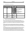
1.2
Option Card Jumper Settings
There are 3 jumper locations on the option card; JP1, JP2, and JP3. The following is a description of the
jumpers and how they need to be set.
JP1 – Write Enable
Always open. Do not install a jumper (factory default).
JP2 – Remote/Local setting upon power-up.
a. Installed – Drive has control upon power-up
b. Not Installed – Option Card has control upon power-up (normal operating condition).
JP3 – Debug Header
Must have jumper across pins 9-10. Do not remove/change jumper (factory default)
Note:
The only jumper setting that can change is JP2; the other two jumpers must remain in factory
default position.
PAGE 10
1.3
26 APR 2000
CH. 1
The Installation Procedure for Drives Under 40 Horsepower
The AF-300E$ Communications Option Cards have been designed to integrate seamlessly with the AF300E$ drive. The option card is installed within the drive cover, so that the NEMA rating of the drive is
maintained after installation of the option card.
1.
Power down the drive.
2.
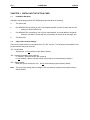
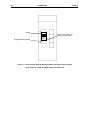
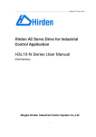
Remove the cover the AF-300E$ drive as shown in the diagram below.
3.
Install the supplied plastic 1/2" standoff (A') in hole (A).
Figure 1.1 - Drive Front Cover Removal Procedure
CH. 1
26 APR 2000
PAGE 11
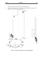
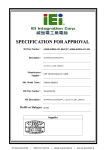
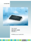
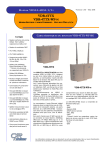
Figure 1.2 - Drive Mounting Holes and Connectors (left), Mounting Hardware (center, not to scale),
and Option Card Location (right). Drive shown is 1/2HP AF-300E$ viewed from the front.
4.
Install the HE300 option board. Use the plastic guides (B) to properly align the bottom of the
option board. Snap the option board into the standoff (A') and option connector (C).
5.
Install the supplied M3 x 5 screw (D') with washer in hole D to secure the option board.
6.
After completing field wiring to the removable terminal strip(s), replace the front cover.
7.
Power up the drive as needed.
PAGE 12
26 APR 2000
CH. 1
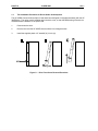
Figure 1.3 - Installing Option Board (Side View of AF-300E$ 1/2HP shown)
1.4
The Installation Procedure for Drives 40 Horsepower and Larger
The AF-300E$ Communications Option Cards have been designed to integrate seamlessly with the AF300E$ drive. The option card is installed within the drive cover, so that the NEMA rating of the drive is
maintained after installation of the option card.
1.
Power down the drive.
2.
Remove the cover from the AF-300E$ using the 11 screws on the front panel.
3.
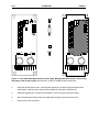
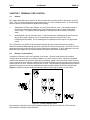
Remove the keypad and the keypad mounting plastic (4 screws) shown below.
CH. 1
26 APR 2000
Keypad
PAGE 13
Option Card located under
keypad mounting plastic
Keypad Mounting Plastic
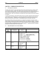
Figure 1.4 - Drive Keypad, Keypad Mounting Plastic and Option Card Location.
Drive shown is a 40HP AF-300E$ viewed from the front.
PAGE 14
26 APR 2000
CH. 1
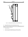
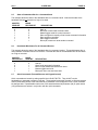
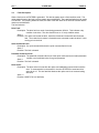
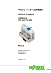
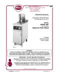
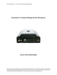
4.
Install corner brackets (A') on bottom corners of interface board (A).
5.
Install corner brackets (A') on metal bracket (B') using the supplied M3 x 5 screws and lock
washers in the corner bracket mounting holes (C).
E
P1
P2
A
A
Al
E
Bl
E
C
Figure 1.5 - Option Card Assembly Front and Side View (Right)
CH. 1
26 APR 2000
PAGE 15
6.
Install the assembled board into the drive using the M3 x 5 screws and lock washers in the
mounting holes (E). If you used the plastic standoff in the upper right hand corner of the board
you may need to use one of the M3 x 5 screws from the HE300KIT399.
7.
Replace the keypad mounting plastic and the keypad.
8.
After completing field wiring to the terminal strip(s), replace the front cover.
9.
Power up the drive as needed.
Note:
The metal standoff included with the HE300KIT401 can be used in place of the plastic standoff that
comes with the drive. The plastic standoff is the preferred method of installation, but if the metal standoff
is to be used the steps below should be followed.
1.
Once the keypad and keypad mounting plastic is removed, remove the plastic standoff in the
upper right corner of the drive board by holding the screw under the standoff with your finger,
while unscrewing the plastic standoff.
2.
Once the standoff is removed, screw on the metal standoff that is supplied with the
HE300KIT401.
3.
Instead press the interface board down onto the metal standoff until it snaps into place.
4.
To remove the board you may need to use a pair of fine tipped pliers to squeeze the tip of the
metal standoff together in order for the board to snap off of the standoff.
PAGE 16
26 APR 2000
NOTES
CH. 1
CH. 2
26 APR 2000
PAGE 17
CHAPTER 2: COMMUNICATIONS PROTOCOL
2.1
Accessing Drive Parmeters
The Option card consumes 2 input words and produces 2 output words according to its relative position
on an Interbus-S network. Through these network words, the Interbus-S master can both send and
receive data to the associated drive. The drive’s terminal, speed reference and configuration parameters,
which are typically accessed through the drive’s terminal and keypad, are also accessible over the
Interbus-S network. Most of the parameters are writeable (with certain limitation) while all the parameters
are readable.
To access a drive parameter, the Interbus-S master must set a command, parameter number and data (if
a write operation) in the outgoing words. The incoming words reflect the command success and return
data (if a read operation). Handshake bits are also transferred in the outgoing and incoming words to
synchronize the send and receive transfer. The handshake sequence is covered in section 2.4.
All parameters whether terminal, speed reference or configuration are assigned a parameter number
(listed in chapter 4) which must be supplied as part of the read or write sequence. However, an exception
to this process is the forward and reverse bits contained in the terminal command parameter. These bits
are directly writable in an outgoing word and do not require a parameter number or handshake sequence.
These bits are called quick commands and are covered in section 2.7. Likewise, the drive’s run and fault
status are also directly available in an incoming word.
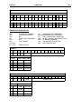
2.2
Output Words(Data sent out from the Master)
Table 2.1 – Output Words
IB-OUT
BYTE
NUMBER
0
1
DEFINITION
VALUE
Parameter Number
Status/Command Bits
0-7Ah or FFh
7 6 5 4 3 2 1 0
Master Handshake Send
Master Handshake Receive
Read/Write
Forward*
Reverse*
Not Defined
Not Defined
Keypad Control
2
Low Byte of data to
the drive
Depends on Valid
Value for Parameter
Number (See
Chapter 3)
3
High Byte of data to
Depends on Valid
the drive
Value for Parameter
Number (See
Chapter 3)
* FORWARD and REVERSE can NOT be 1 at the same time.
PAGE 18
2.3
26 APR 2000
CH. 2
Input Words(Data sent out by the Drive)
Table 2.2 – Input Words
IB-IN BYTE
NUMBER
0
1
DEFINITION
VALUE
Parameter Number
Status/Command
Bits
0-7Ah or FFh
7 6 5 4 3 2 1 0
Drive Handshake Send
Drive Handshake Receive
Run
Drive Fault
Quick Command Fault
Parameter Command Fault
Drive Active
Keypad Control Status
2.4
2
Low Byte of data
from the drive
3
High Byte of data
from the drive
Depends on Valid
Value for Parameter
Number (See
Chapter 3)
Depends on Valid
Value for Parameter
Number (See
Chapter 3)
Parameter Transfer with Handshake Description
Both read and write operations to the drive require the drive parameter number in IB-OUT
BYTE 0. The specific operation (Read or Write) is specified in the ‘Read/Write’ bit in IB-OUT BYTE 1.
The option card is then commanded to process the request by toggling the ‘Master Handshake Send’ bit
in IB-OUT BYTE 1. When performing a read operation, the option card indicates that valid data from the
‘read’ command is ready in IB-IN BYTES 2-3 by toggling the ‘Drive Handshake Send’ bit in the IB-IN
BYTE 1.
The option card actually looks for inequalities in the ‘Master Send/Drive Receive’ handshake pair to
trigger a command. That is, if the ‘Master Handshake Sent’ bit is not equal to the ‘Drive Handshake
Receive’, the option card processes the contents of the IB-OUT BYTES as a command and toggles the
‘Drive Handshake Receive’ bit. The handshake bits are now set equal indicating that it is ready for a new
command.
If the command is a read, the option card sets the ‘Drive Handshake Send’ bit opposite to that of the
‘Master Handshake Receive’ bit such to indicate that the requested data is now present in IB-IN BYTES
2-3. The master should then toggle the ‘Master Handshake Receive’ bit to be ready for the next
operation. Should the master not toggle the ‘Master Handshake Receive’ bit or at any time this bit
becomes unequal to the ‘Drive Handshake Send’ bit, a one-second timer is started. Should the timer
time-out, the option card sets the ‘Drive Handshake Send’ bit to match the ‘Master Handshake Receive’
bit. This timeout guarantees a toggle action should the master lose synchronization with the option card.
CH. 2
2.5
26 APR 2000
PAGE 19
State of Handshake Bits for a Command Send
This example shows the state of the handshake bits for a command send. Note that the state of the
handshake bits are not based on a high or low state.
MASTER
SEND BIT
0
0
1
1
1
1
1
2.6
DRIVE
RECEIVE BIT
0
0
0
0
0
1
1
DESCRIPTION
Start up
Bits equal, master loads command data
Master toggles send bit to send command
Slave recognizes inequality of bits & reads command information
Slave performs command
Slave toggles receive bit
Bits equal, master can send another command
Handshake Bits Status For A Command Receive
This example shows the state of the handshake bits for a command receive. This would happen after a
read parameter command was sent to the drive. Note that the state of the handshake bits are not based
on a high or low state.
MASTER
RECEIVE BIT
0
0
0
1
1
2.7
DRIVE
SEND BIT
0
1
1
1
1
DESCRIPTION
Start up
Slave sends requested information
Bits not equal, Master saves data from slave
Master toggles receive bit
Bits equal, slave can send more data
Quick Commands (Forward/Reverse and Keypad Control)
Quick commands are issued by setting specific bits in IB-OUT BYTE1. They do NOT require
handshaking or parameter numbers to activate. The supported commands (forward, reverse and keypad
control) are actually written to the associated drive parameter in the background once a quick command
bit changes state. Unpredictable results occur if the associated terminal parameter (96) or option status
(122) parameters are written in conjunction with the quick commands.
PAGE 20
26 APR 2000
NOTES
CH. 2
CH. 3
26 APR 2000
PAGE 21
CHAPTER 3: COMMUNICATIONS CONTENT
3.1
Communication Content Overview
The protocol requires a parameter number byte and status/command byte when sending a command to
the drive option card. The data word is only required if a write command is initiated. The option card will
respond to a read command by sending the parameter number, status/error bits and the drive data value
for the parameter number.
There are two types of commands; a parameter access command and a quick command. There are
three quick command bits; forward, reverse and keypad control. They eliminate the need to execute the
same function using a parameter and data value. The parameter access command uses the parameter
and data value to access data in the drive. The two commands can be used together in one write
command. This allows the drive speed and the drive direction to be set in one write. However, note that
the quick command is executed immediately before the read/write parameter request.Chapter 3
discusses the parameter numbers and their descriptions.
3.2
IB-OUT BYTE 1 - Status/Command Bit Definitions
Master Handshake Send:
Description: Lets slave know a new command has been sent.
Bit Number:
0
Bit Value:
Toggles
Master Handshake Receive:
Description: Lets slave know data has been received
Bit Number:
1
Bit Value:
Toggles
Read/Write:
Description: Lets slave know parameter is read from or written to
Bit Number:
2
Bit Value:
0 = Read
1 = Write
Forward:
Description: Quick command to run drive forward (Same as writing a 1 to parameter 96)
Bit Number:
3
Bit Value:
Change from 0 to 1 = Forward* Change from 1 to 0 = Stop Forward
Note: If forward is changed from a 1 to a 0 and reverse is changed from 0 to a 1 at the same time,
the drive will immediately go into run reverse. It will not stop and then go reverse.
Reverse:
Description: Quick command to run drive reverse (Same as writing a 2 to parameter 96)
Bit Number:
4
Bit Value:
Change from 0 to1 = Reverse* Change from 1 to 0 = Stop Reverse
Note: If reverse is changed from a 1 to a 0 and forward is changed from 0 to a 1 at the same time,
the drive will immediately go into run forward. It will not stop and then go forward.
Keypad Control:
Description: Quick command to give user keypad control on the drive
(Same as writing a 40h to parameter 122)
Bit Number:
7
Bit Value:
0 = Option card take control
1 = Keypad take control
* FORWARD and REVERSE SHOULD NEVER BE 1 AT THE SAME TIME.
PAGE 22
3.3
26 APR 2000
CH. 3
IB-IN BYTE 1 - Status/Error Bit Definitions
Drive Handshake Send:
Description: Lets master know the slave has sent data.
Bit Number:
0
Bit Value:
Toggles
Drive Handshake Receive:
Description: Lets master know slave has received command.
Bit Number:
1
Bit Value:
Toggles
Run:
Description: Lets master know that the drive is running.
Bit Number:
2
Bit Value:
0 = Not Running
1 = Running
Drive Fault:
Description: Lets master know a fault condition exists in the drive.
Bit Number:
3
Bit Value:
0 = No fault condition 1 = Fault condition
Quick Command Fault:
Description: Lets master know the last quick command was not successful
Bit Number:
4
Bit Value:
1 = Fault occurred
Cleared when quick command is successful
Parameter Command Fault:
Description: Lets master know the last parameter command was not successful
Bit Number:
5
Bit Value:
1 = Fault occurred
Cleared when parameter command is successful
Drive Active:
Description: Lets master know the option card is O.K and ready to communicate.
Bit Number:
6
Bit Value:
0 = Problem with option card
1 = Option card O.K
Keypad Control Status:
Description: Lets master know what the control status is.
Bit Number:
7
Bit Value:
0 = Option card has control
1 = Drive keypad has control
CH. 3
3.4
26 APR 2000
PAGE 23
Fault Description
When a fault occurs a STATERR is generated. This lets the master know a fault condition exists. The
option card will react to the fault once the master issues a MODACK. There are four faults that can cause
a STATERR. The following details the faults, the state of the fault when the STATERR is issued and the
reaction to the MODACK.
The four faults are:
Drive Fault:
Description: The drive fault is a result of monitoring parameter 105 bit 4. This indicates a trip
condition in the drive. The drive fault bit is set to 1 if a trip condition exists.
State: 1
Reaction: The option card resets the drive, clears the forward and reverse bits and clears the
fault. The master has to reissue a forward/reverse command to start the drive if it was
running prior to the fault.
Quick Command Fault:
Description: If a quick command fails then the quick command fault bit is set.
State: 1
Reaction: The fault is cleared.
Parameter Command Fault:
Description: The parameter command fault is set if the option card receives an invalid parameter
number or an invalid data value for a given parameter
State: 1
Reaction: The fault is cleared.
Drive Active:
Description: The drive active bit is set after the option card establishes communication with the
drive. If communication is unsuccessful, then the STATERR is issued and drive
active bit is a 0. This is a fatal fault because the option card is not communicating
with drive.
State: 0
Reaction: NONE (This is a fatal fault)
PAGE 24
3.5
26 APR 2000
CH. 3
Communication Examples
The following examples describe what bits are manipulated and when a transmit and receive is to take
place. The actual code is not shown but the handshaking example program could be used with the
correct bits manipulated as the examples show. The steps for the send and receive routines are defined
once again since they are an integral part of the examples.
SEND ROUTINE
a. Check MASTER HANSHAKE SEND = DRIVE HANDSHAKE REC
b. if not equal then read IB-IN BYTE 1 (input status), go to a.
c. if equal then toggle MASTER HANDSHAKE SEND and load IB-OUT byte 1 with status byte.
RECEIVE ROUTINE
a. Read IB-IN BYTE 1 (input status)
b. If DRIVE HANSHAKE SEND not equal MASTER HANDSHAKE RECEIVE
c. save IB-IN BYTE 0
d. convert IB-IN BYTE 2 & IB-IN BYTE 3 to input word value
1. A drive speed value of 60.0 Hz is to be written to the drive.
The table in chapter 3 shows that parameter 95 is the high resolution frequency setting parameter. It
uses format 14 to put the data in the correct format to send to the drive. Format 14 shows frequency to
pulses is the absolute value of 60.0 x 15 = 900 (384h) pulses.
STEPS:
1. Load IB-OUT byte 0 with 95 (5Fh)
2. Load IB-OUT byte 2 with 84h (low byte of 900 (384h) )
3. Load IB-OUT byte 3 with 3 (high byte of 900 (384h) )
4. Set READ/WRITE bit
5. Call SEND ROUTINE
2. The drive is to run forward (no other commands).
• Set ‘Forward’ quick command in IB-OUT BYTE 1.
3. The drive is to run forward at 60.0 Hz
This can be accomplished with one write to the drive option card. It is a combination of examples 1 and
2. The write parameter access command will be executed first followed by the forward command.
STEPS:
1. This can be accomplished with two writes to the drive option card.
2. Load IB-OUT byte 2 with 84h (low byte of 900 (384h)
3. Set ‘Read/Write’ bit
4. Call Send Routine.
5. Set ‘Forward’ quick command in IB-OUT BYTE 1
6. Call SEND ROUTINE
4. The actual drive speed value is to be read from the drive.
The table in chapter 3 shows that parameter 101 is the output frequency parameter and it is read only. It
uses format 14 to convert the drive data from pulses to Hz.
STEPS:
1. Load IB-OUT byte 0 with 101 (65h)
2. Clear READ/WRITE bit
3. Call SEND ROUTINE
4. Call READ ROUTINE
5. frequency = value/15
CH. 4
26 APR 2000
PAGE 25
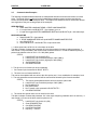
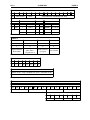
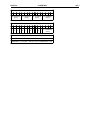
CHAPTER 4: AF300E$ DRIVE PARAMETERS
Table 4.1 – Drive Parameters
PA RA M
NU M BE R
PAR AM E TE R
DE S C RI P TIO N
F C* M I NI MU M
M AX I MU M
U NIT
FO R M AT
LE N GTH
R EA D /
W RITE
C H AN G E
W HILE
R U NN IN G
0
F req u en cy C o m m a nd
00
0
2
-
0
1 W O RD
R/ W
N
1
O pe ra tion M e th od
01
0
1
-
0
1 W O RD
R/ W
N
2
M axim u m F req u en c y
02
50
4 00
Hz
0
1 W O RD
R/ W
N
3
Ba se Fre qu e nc y 1
03
50
4 00
Hz
0
1 W O RD
R/ W
N
4
R a te d V olta g e 1
04
0, 80
4 80
V
0
1 W O RD
R/ W
N
5
A c ce lera tio n Tim e 1
05
0.01
3 6 00
s
5
1 W O RD
R/ W
Y
6
D ece lera tio n Tim e 1
06
0.01
3 6 00
s
5
1 W O RD
R/ W
Y
7
To rqu e B oo s t 1
07
0
20
-
1
1 W O RD
R/ W
Y
8
E le c. Th e rm al O L (S ele c t)
08
0
2
-
0
1 W O RD
R/ W
Y
9
E lec. Th erm a l O L (L e v el)
09
Ra te d x20
R at ed x1 35
A
6
1 W O RD
R/ W
Y
10
R est art af te r P ow er F ailure
10
0
4
-
0
1 W O RD
R/ W
N
11
Fre q ue n cy Lim it er (H igh )
11
0
4 00
Hz
0
1 W O RD
R/ W
Y
12
Fre qu e ncy L imite r (L ow )
12
0
4 00
Hz
0
1 W O RD
R/ W
Y
13
B ias F req u en cy
13
0
4 00
Hz
0
1 W O RD
R/ W
Y
14
G ain (F re q. Se ttin g S ig n al)
14
0
2 00
%
1
1 W O RD
R/ W
Y
15
To rq ue L im ite r (Driv ing )
15
20
18 0 ,2 55
%
0
1 W O RD
R/ W
Y
16
To rqu e Lim it er (B ra k ing )
16
0,20
18 0 ,2 55
%
0
1 W O RD
R/ W
Y
17
D C B rake (S ta rting Fre q .)
17
0
60
Hz
1
1 W O RD
R/ W
Y
18
DC B rak e (B ra k e L e vel)
18
0
1 00
%
0
1 W O RD
R/ W
Y
19
DC B ra ke (B ra k ing T im e )
19
0
30
s
1
1 W O RD
R/ W
Y
20
M ultis te p Freq S e ttin g 1
20
0
4 00
Hz
2
1 W O RD
R/ W
Y
21
M ultis te p Freq S e ttin g 2
21
0
4 00
Hz
2
1 W O RD
R/ W
Y
22
M ultis te p Freq S e ttin g 3
22
0
4 00
Hz
2
1 W O RD
R/ W
Y
23
M ultis te p Freq S e ttin g 4
23
0
4 00
Hz
2
1 W O RD
R/ W
Y
24
M ultis te p Freq S e ttin g 5
24
0
4 00
Hz
2
1 W O RD
R/ W
Y
25
M ultis te p Freq S e ttin g 6
25
0
4 00
Hz
2
1 W O RD
R/ W
Y
26
M ultis te p Freq S e ttin g 7
26
0
4 00
Hz
2
1 W O RD
R/ W
Y
27
Ele c. Th e rm al O L (D B R e s.)
27
0
2
-
0
1 W O RD
R/ W
Y
28
S lip C o mp e nsa tio n C o nt rol
28
-9 .9
5
Hz
1
1 W O RD
R/ W
Y
29
Torq u e V ect or C o nt rol
29
0
1
-
0
1 W O RD
R/ W
N
30
N um b e r of M o to r P o le s
30
2
14
-
0
1 W O RD
R/ W
N
31
Fu n c tion B loc k (3 2 -41 )
31
0
1
-
0
1 W O RD
R/ W
Y
32
X 1 - X 5 Te rm in al Fu n c tion
32
0
0x2 2 22
-
11
1 W O RD
R/ W
N
* The performance of these parameters has not been fully evaluated at the time of publication of this manual.
PAGE 26
PA RA M
NU M BE R
26 APR 2000
PA RA M E TE R DE S C RI P TIO N
CH. 4
C H AN G E
R EA D /
W HI LE
F C* M INI MU M M AX I MU M U NI T FOR M AT LE N GTH W RI TE R U NN IN G
33
A cc e lera tio n Tim e 2
33
0. 01
3 6 00
s
5
1 W O RD
R /W
Y
34
D ec e lera tio n Tim e 2
34
0. 01
3 6 00
s
5
1 W O RD
R /W
Y
35
A cc e lera tio n Tim e 3
35
0. 01
3 6 00
s
5
1 W O RD
R /W
Y
36
D ec e lera tio n Tim e 3
36
0. 01
3 6 00
s
5
1 W O RD
R /W
Y
37
A cc e lera tio n Tim e 4
37
0. 01
3 6 00
s
5
1 W O RD
R /W
Y
38
D ec e lera tio n Tim e 4
38
0. 01
3 6 00
s
5
1 W O RD
R /W
Y
39
B a s e F re qu e nc y 2
39
50
4 00
Hz
0
1 W O RD
R /W
N
40
R a te d V olta g e 2
40
0, 80
4 80
V
0
1 W O RD
R /W
N
41
To rqu e B oo s t 2
41
0 .1
20
-
1
1 W O RD
R /W
Y
42
F u n c tion B lock (4 3 -51 )
42
0
1
-
0
1 W O RD
R /W
Y
43
F M P Term in al (P uls e R a te M u lt .)
43
6
1 00
-
0
1 W O RD
R /W
Y
44
F MP Te rm ina l (Vo lt ag e A dju st)
44
50
1 20
-
0
1 W O RD
R /W
Y
45
F MA Te rm ina l (Vo lt ag e A dju st)
45
65
1 03
-
0
1 W O RD
R /W
Y
46
F M A Term in al (F u n c tion )
46
0
3
-
0
1 W O RD
R /W
Y
47
Y 2 - Y 5 Te rm in a l F u n c tion (low w ord ) 47
0
0 xF F F F
-
12
R /W
N
48
Y1 Te rm in a l F un ctio n(h igh w ord )
0
0 xF
-
13
R /W
N
49
FA R Fu nct io n S ig n al (H y ste res is )
48
0
10
Hz
1
1 W O RD
R /W
Y
50
F D T F un ctio n (L e v el)
49
0
4 00
Hz
0
1 W O RD
R /W
Y
51
F D T Fu n ction (H ys te res is)
50
0
30
Hz
1
1 W O RD
R /W
Y
52
O L F u n c tion S ign a l (L e v el)
51
A
6
1 W O RD
R /W
Y
53
F u n c tion B lock (5 3 -59 )
52
0
1
-
0
1 W O RD
R /W
Y
54
J u m p F req u en c y (J u m p F req . 1 )
53
0
4 00
Hz
0
1 W O RD
R /W
N
55
J u m p F req u en c y (J u m p F req . 2 )
54
0
4 00
Hz
0
1 W O RD
R /W
N
56
J u m p F req u en c y (J u m p F req . 3 )
55
0
4 00
Hz
0
1 W O RD
R /W
N
57
J u m p F req u en c y (H ys te res is )
56
0
30
Hz
0
1 W O RD
R /W
N
58
S ta rtin g F req u en cy (Fre q .)
57
0 .2
60
Hz
1
1 W O RD
R /W
N
59
S tart in g Fre qu e ncy (H o ld ing T im e )
58
0
10
s
1
1 W O RD
R /W
N
60
F re q . S etting S ign a l F ilte r
59
0. 01
5
s
2
1 W O RD
R /W
Y
61
F u n c tion B lock (6 1 -79 )
60
0
1
-
0
1 W O RD
R /W
Y
62
L E D M o nito r (F u n c tion )
61
0
8
-
0
1 W O RD
R /W
Y
63
L E D M o nito r (D isp lay a t S t op M o de )
62
0
1
-
0
1 W O RD
R /W
Y
64
C o e ff. f or M a c h in e & Lin e S p e ed
63
0. 01
2 00
-
2
1 W O RD
R /W
Y
65
L CD M o nito r
64
0
4
-
0
1 W O RD
R /W
Y
R a te d x 20 R at ed x 1 35
2 W O RD
* The performance of these parameters has not been fully evaluated at the time of publication of this manual.
CH. 4
26 APR 2000
PAGE 27
PA RA M
NU M BE R
PA RA M E TE R DE S C RI P TION
66
P at te rn O pe ratio n (M od e S ele c t)
65
0
3
67
P a tte rn O pe ra tion (S ta g e 1 )
66
0
68
P a tte rn O pe ra tion (S ta g e 2 )
67
69
P a tte rn O pe ra tion (S ta g e 3 )
68
70
P a tte rn O pe ra tion (S ta g e 4 )
71
F C* M I NI MU M M AX I MU M
U NIT
C H AN G E
R EA D / W HILE
FO R M AT LE N G TH W RITE R U NN IN G
-
0
1 W O RD
R/ W
N
6 0 00
s /-
7
1 W O RD
R/ W
Y
0
6 0 00
s /-
7
1 W O RD
R/ W
Y
0
6 0 00
s /-
7
1 W O RD
R/ W
Y
69
0
6 0 00
s /-
7
1 W O RD
R/ W
Y
P a tte rn O pe ra tion (S ta g e 5 )
70
0
6 0 00
s /-
7
1 W O RD
R/ W
Y
72
P a tte rn O pe ra tion (S ta g e 6 )
71
0
6 0 00
s /-
7
1 W O RD
R/ W
Y
73
P a tte rn O pe ra tion (S ta g e 7 )
72
0
6 0 00
s /-
7
1 W O RD
R/ W
Y
74
A c c ./ De c. P a tte rn (M od e S ele c t)
73
0
2
-
0
1 W O RD
R/ W
N
75
E n erg y S av in g O pe ra tion
75
0
1
-
0
1 W O RD
R/ W
N
76
R ev. P ha se S eq u en c e Lo c k
76
0
1
-
0
1 W O RD
R/ W
N
77
Da ta In it ia lizin g (D a ta R e s e t)
77
0
1
-
0
1 W O RD
R/ W
N
78
La n gu a ge (Ja pa n es/ E ng lis h )
78
0
3
-
0
1 W O RD
R/ W
Y
79
L C D D is p lay B rig ht ne ss
79
0
10
-
0
1 W O RD
R/ W
Y
80
Fu n ction B loc k (8 1 -94 )
80
0
1
-
0
1 W O RD
R/ W
Y
81
M ot or S o u nd (Ca rrier F req u en c y)
81
0
10
-
0
1 W O RD
R/ W
Y
82
A u to Re s ta rt (R e sta rt Tim e )
82
0
5
s
1
1 W O RD
R/ W
N
83
A u to R es tart (Freq . F all Ra te )
83
0
1 00
H z /s
2
1 W O RD
R/ W
N
84
A u to Re se t (Tim e s )
84
0
7
-
0
1 W O RD
R/ W
Y
85
A ut o R es e t (R e s et In te rval)
85
2
20
s
0
1 W O RD
R/ W
Y
86
M o to r 1 (C a pa c ity )
86
0
3
-
0
1 W O RD
R/ W
N
87
M ot or 1 (R at ed C urre n t)
87
0
2 0 00
A
6
1 W O RD
R/ W
N
88
M o to r 1 (N o-L o ad C urre n t)
88
0
2 0 00
A
6
1 W O RD
R/ W
N
89
M ot or 2 (R at ed C urre n t)
89
0
2 0 00
A
6
1 W O RD
R/ W
N
90
M o to r 1 Im pe d an c e (Tun ing )
90
0
1
-
0
1 W O RD
R/ W
N
91
M ot or 1 Im p ed a nce (% R 1
S et ting )
91
0
50
%
2
1 W O RD
R/ W
Y
92
M o to r 1 Im pe d an c e (% X 1
S et ting )
92
0
50
%
2
1 W O RD
R/ W
Y
95
93
Da ta P ro te ction
0
1
-
0
1 W O RD
R/ W
N
9 4*
A dd ition al V 1 A na log Vo lta ge
-10
10
V
0
1 W O RD
R/ W
Y
95
H ig h Re s . Fre q ue n cy S etting
(P u ls e s)
-6 0 00
14
1 W O RD
R/ W
Y
96
Te rm in a l I np u t/O u tp u t (low w ord )
B IT M A P
B IT M A P
-
4
1 6 b its
R/ W
Y
97
Te rm ina l In pu t/O ut pu t (h igh w ord )
B IT M A P
B IT M A P
-
4
1 6 b its
R/ W
Y
9 8*
O ut pu t F req ue n c y Co m p en s a tion
I np u t
-6 0 00
14
1 W O RD
R/ W
Y
6 0 00 P u lse s
6 0 00 P u lse s
* The performance of these parameters has not been fully evaluated at the time of publication of this manual.
PAGE 28
PA RA M
NU M BE R
26 APR 2000
PA RA M E TE R DE S C RI P TION
99
D riv e Torq u e L im it S et ting
1 00
B ra k in g Torq u e L im it S et ting
1 01
O ut pu t F req u en c y
1 02
O u tp u t C urre n t
1 03
1 04
1 05
O pe ra tion S ta tu s
1 06
Trip H isto ry (low w ord )
CH. 4
F C* M INI MU M M AX I MU M
U NI T
C H AN GE
R EA D / W HI LE
FOR M AT LE N G TH W RI TE R U NN IN G
20
18 0 ,2 55
%
0
1 W O RD
R /W
Y
0, 20
18 0 ,2 55
%
0
1 W O RD
R /W
Y
14
1 W O RD
R
Y
%
10
1 W O RD
R
Y
O u tp u t Vo lta ge
%
10
1 W O RD
R
Y
O ut pu t To rq ue
%
10
1 W O RD
R
Y
-
8
1 6 b its
R
Y
-
3
1 W O RD
R
Y
-6 0 00
B IT M A P
6 0 00 P u ls e s
B IT M A P
1 07
T rip H ist ory (h igh w ord )
-
3
1 W O RD
R
Y
1 08
In v ert er C a pa city
-
15
1 W O RD
R
Y
1 09
To ta l O pe ra tion T im e
h
0
1 W O RD
R
Y
110
I nve rte r R at ed C urre n t
A
16
1 W O RD
R
Y
111
F in Tem p e rat ure
C
0
1 W O RD
R
Y
112
In te rna l Tem p e rat ure
C
0
1 W O RD
R
Y
113
O u tp u t Te rm in a l C o nd ition
-
9
1 6 b its
R
Y
114
V 2 Term in al Vo lta ge
V
1
1 W O RD
R
Y
115
V 1 t erm in al Vo lta ge
V
1
1 W O RD
R
Y
116
C 1 Term in al C urre n t
mA
1
1 W O RD
R
Y
P u ls e s
0
1 W O RD
R
Y
V
1
1 W O RD
R
Y
11 7 **
118
B IT M A P
B IT M A P
F M P F req u en cy
F M P O u tp u t Vo lta ge
119
F M A O u tp u t Vo lta ge
V
1
1 W O RD
R
Y
1 20
I nve rte r Te rm in a l I np u t (low w ord )
B IT M A P
B IT M A P
-
4
1 6 b its
R
Y
1 21
In vert er Te rm ina l In pu t (h igh w ord )
B IT M A P
B IT M A P
-
4
1 6 b its
R
Y
1 22
O p tion S ta tu s
B IT M A P
B IT M A P
-
17
1 6 b its
R /W
Y
** Not operational at this time
CH. 4
4.2
26 APR 2000
PAGE 29
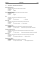
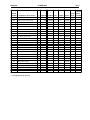
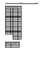
Data Formats
The Drive Parameters listed in the previous pages list, among other things, the "format" in which the data
is presented. There are 17 different formats, all listed in this manual section. For further details beyond
this manual, consult the user documentation provided with the AF-300E$ drive.
FORMAT 0
Direct Translation
F ORMAT 1
READ
WRITE
/10
X10
Format 3
LOW W ORD
15
14
13
0
0
0
12
11
10
9
8
7
6
5
0
0
0
23
22
21
0
0
0
PRIOR FAULT #1
4
3
2
1
0
PRESENT FAULT
HIG H W ORD
31
30
29
0
0
0
28
27
26
25
24
PRIOR FAULT #3
20
19
18
17
16
PRIOR FAULT #2
Fault Cod es
Code
Type
Description
Code
Type
Description
0
-
No Trip History
12
OH3
Overheat (Internal Temp.)
1
OC1
Overcurrent During Acc.
13
OH2
External Fault
2
OC2
Overcurrent During Dec.
14
dbH
DB Resistor Overload
3
OC3
Overcurrent Steady State Running
15
FUS
DC Fuse Burnout
4
EF
Ground Fault
16
Er1
Memory Error
5
OV1
Overvoltage During Acc.
17
Er3
Inverter CPU Error
6
OV2
Overvoltage During Dec.
18
Er4
Option COmmunications Error
7
OV3
Overvoltage Steady State Running
19
Er5
Option Malfunction
8
LV
Low Voltage
20
Er6
Keypad Panel Operation Error
9
OL
Electric Thermal Overload Relay
21
Er7
Auto Tuning Error
10
OLU
Inverter Overload
22
Er2
Keypad Panel Communication Error
11
OH1
Heatsink Overheat
PAGE 30
26 APR 2000
CH. 4
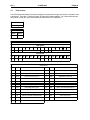
F ORMAT 4
LOW W ORD
15
14
DCB AUT
13
12
11
10
9
8
7
6
5
4
3
2
1
0
PU
DOWN
UP
RT2
RT1
X3
X2
X1
RST
THR
BX
HLD
REV
FWD
HIG H W ORD
31
30
29
28
27
26
25
24
23
22
21
20
19
18
17
16
0
0
0
0
0
0
0
0
0
0
0
0
0
0
PRT
VF2
ABBREVIATION DEFINITIONS:
FWD
REV
HLD
BX
THR
RST
X1,X2,X3,
RT1, RT2
RUN DRIVE FORWARD
RUN DRIVE REVERSE
N/A
COAST STOP COMMAND
N/A
FAULT RESET
UP
DOWN
PU
AUT
DCB
VF2
PRT
INCREMENT SET FREQUENCY
DECREMENT SET FREQUENCY
LINE TO INVERTER TRANSITION
SELECT 4-20mA FOR FREQ SETTING
DC BRAKE COMMAND
2ND MOTOR V/F SELECTION
DATA PROTECTION
SEE GEI-100211
F ORMAT 5
15
14
13
12
0
0
0
0
BASE
11
10
9
BASE
8
7
6
5
4
3
2
1
0
ACCELERATIO N / DECELERATION TIME
ACCEL / D ECEL TIME
0
10ms
1-999
0.01-9.99s
1
0.1s
100-199
10.0-99.9s
2
1s
100-199
100-999s
3
10s
100-360
1000-3600s
F ORMAT 6
15
14
13
12
0
0
0
0
BASE
11
10
BASE
CURRENT DATA
0
0.01A
1-999
0.01-9.99A
1
0.1A
100-999
10.0-99.9A
2
1.0A
100-999
100-999A
3
10A
100-200
1000-2000A
9
8
7
6
5
4
CURRENT DATA
3
2
1
0
CH. 4
26 APR 2000
PAGE 31
F ORMAT 7
15
DIR
14
13
12
11
TIME SELECT
DIR ECTION
10
9
8
BASE
7
6
5
4
3
2
1
0
ACCELERATION / DECELERATION TIME
TIME SELECT
BASE
ACCEL / D ECEL TIME
0
FWD
0
TIME 1
0
0.01S
1-999
0.01-9.99A
1
REV
1
TIME 2
1
0.1S
100-999
10.0-99.9A
2
TIME 3
2
1.0S
100-999
100-999A
3
TIME 4
3
10S
100-600
1000-6000A
F ORMAT 8
3
2
1
0
DC Brake Applying
RUN
REVERSE
FORWARD
7
6
5
4
Keypad O peration
Status (LED)
Data Change Priority
Option Side: 1,
Keypad Side: 0
RUN Command
by Keypad
Trip Condition
F ORMAT 9
7
6
5
4
3
2
1
0
0
0
0
Y5
Y4
Y3
Y2
Y1
FORMAT 10
(DRIVE VALUE / 4096) X NAMEPLAT E VALUE = DESIRED VALUE
DRIVE VALUE / 40.96 = PERCENT VALUE
FORMAT 11
WRITE
15
14
13
12
X1/X2 TERMINAL (0-FH)
11
10
9
8
X3 TERMINAL (0-FH)
7
6
5
4
3
X4 TERMINAL (0-FH)
2
1
0
X5 TERMINAL (0-FH)
READ
7
6
X5
5
4
X4
3
2
X3
1
0
X1/X2
PAGE 32
26 APR 2000
CH. 4
FORMAT 12
15
14
13
12
Y2 TERMINAL
(0-FH)
11
10
9
8
7
6
5
4
3
2
1
0
Y3 TERMINAL
(0-FH)
Y4 TERMINAL
(0-FH)
Y5 TERMINAL
(0-FH)
FORMAT 13
15
14
13
12
11
10
9
8
7
6
5
4
3
2
1
0
0
0
0
0
0
0
0
0
0
0
0
0
Y1 TERMINAL
(0-FH)
FORMAT 14
PULSES TO FREQUENCY = PULSES / 15
FREQUENCY TO PULSES = absolute value of (FREQUENCY X 15)
CH. 4
26 APR 2000
FORMAT 15
200V Series
400V Series
Capacity (HP)
Data
Capacity (HP)
Data
1/4
2
1/2
131
1/2
3
1
132
1
4
2
133
2
5
3
134
3
6
5
135
5
7
7.5
136
7.5
8
10
137
10
9
15
138
15
10
20
139
20
11
25
140
25
12
30
141
30
13
40
142
40
14
50
143
50
15
75
144
75
16
55
145
55
17
100
146
100
18
125
147
125
19
150
148
175
149
200
150
250
151
300
152
FORMAT 16
Capacity (HP)
FORMULA
30HP and below
CURRENT = DATA / 100
40HP and above
CURRENT = DATA / 10
PAGE 33
PAGE 34
26 APR 2000
CH. 4
FORMAT 17
3
2
1
0
Terminal Input
(Run Command Input)
thru option card
(See olso P1)
High Resolution Frequency
Setting thru option card
(See also P0)
0
0
7
6
5
4
0
1 = Local (Keypad) Control,
0 = Remote (Option Card) Control
Function Input thru
Option card
Output Frequency
Compensation thru
Option card
11
10
9
8
0
0
0
0
15
14
13
12
0
0
0
0
CH. 5
26 APR 2000
PAGE 35
CHAPTER 5: TERMINAL STRIP CONTROL
5.1
General
This chapter describes how to allow the VF Drive terminal strip to assume partial or total control of the VF
Drive. This VF Terminal Strip control can be temporary or on a more permanent basis. VF Terminal Strip
control is desired for several different applications including
1.
Switching the VF Drive from "Remote" to "Local" mode and vice-versa. This transfers control of
the drive from the Network Master/Option Card (Remote mode) to the VF Drive terminal strip
(Local mode). This typically allows an operator to manually override the machine "automatic"
mode.
2.
Acquiring data only from the Option Card. Control functions are handled through the VF terminal
strip by some other controller, such as a closed loop controller like the GE Fanuc Axis
Positioning Module (APM). This is advantageous for applications which require very tight speed
control.
The VF Drives are very flexible in their operation and allow the drive control functions to be divided
between the Network Master(through the option card) and the VF Drive terminal strip. One of the VF Drive
parameters controls how the various drive control functions are distributed. VF Drive Parameter 122 is the
parameter which assigns control functions between the option card and the terminal strip.
5.2
Remote / Local Operation
A definition of "Remote" and "Local" Operation is as follows. "Remote" mode refers to the machine
condition when the Controller, the Interbus-S Master, is in control of the VF Drive. Generally, the Master
makes all the machine logic decisions and performs Start/Stop, Speed Control, and other control functions.
"Local" mode refers to the machine condition when a machine operator, typically through a manual override
located near the VF Drive, assumes control of the VF Drive. Logic decisions are performed by the machine
operator through the use of manual pushbuttons and other switches wired to the VF Drive terminal strip.
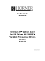
Figure 5.1 shows an example hardwired pushbutton station which might be used in "Local" mode.
Figure 5.1 - Example Remote Panel
Note that some applications may require additional operators. Be sure to consult the VF Drive User's
Documentation for proper wiring instructions.
PAGE 36
26 APR 2000
CH. 4
For effective Remote/Local Operation of the VF Drive, several hardwired pushbuttons are required at the
local station. Generally, they should include buttons to Start and Stop the drive, along with others to control
speed and direction. These hard-wired pushbuttons are wired directly to the Terminal Strip of the VF Drive,
per instructions provided in the VF Drive instruction manual. In addition to the above mentioned
operators, a selector switch wired to a PLC input is required. This operator is required because the VF
Drive is switched from Local to Remote mode (and vice-versa) by communications initiated by the Network
Master.
Upon detecting a Remote-to-Local switch transition, the PLC initiates communications with the VF Drive in
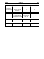
order to set VF Drive Parameter 122. Table 5.1 shows the four most common settings for Parameter 122:
Note: For 48 (30H) and 56 (38H) on drives less than 40hp,
Function 2 needs to be set to a 2 for an external source.
Table 5.1 - VF Drive Parameter 122 Common Data Values
VF D rive Parameter 122
Param eter 122
Param eter 122
Definitio n
Value (in Hex) Value (in Decimal)
003CH
60
PLC (option board) has full control of
Start/Stop & Frequency
0030H
48
VF Drive terminal Strip has full control of
Start/Stop & Frequency
0034H
52
PLC (option board) has Frequency
Control, VF Terminal Strip has Start/Stop
Control
0038H
56
PLC (option board) has Start/Stop
Control, VF Terminal Strip has Frequency
Control
In most applications, the Network Master assumes control of both Start/Stop and Frequency control during
Remote mode, and the VF Terminal Strip assumes these functions during Local mode. Table 9-1 shows
that for these applications, a Remote-to-Local mode transition involves setting Parameter 122 from a value
of 60 (003CH) to a value of 48 (0030H). A Local-to-Remote mode transition requires that Parameter 122
be changed from 48 (0030H) back to 60 (003CH).
CH. 6
26 APR 2000
PAGE 37
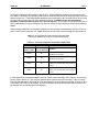
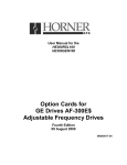
CHAPTER 6: WIRING DIAGRAMS
In nois y envir onm e nts:
IN S he ild an d OU T S h eild m a y be tied toge ther
if no G ND potential e xists betw een de vic es .
W ir e mu s t be a tt ache d
to ear th gr ou nd
co nn ec tion o n d rive
IN
P1
S H EIL D
1
0
Y ELL O W
1
6
2
7
3
8
4
9
5
G RE EN
G RE Y
P IN K
BRO W N
ID O 1
-ID O 1
ID I1
- ID I1
CO M
OUT
P2
1
1
2
2
3
3
4
4
5
5
6
6
1
0
S HE I LD
ID I2
- ID I2
ID O 2
-ID O2
CO M
GR E Y
P INK
YELLOW
G R EEN
BR O W N
1
6
2
7
3
8
4
9
5
C1
D B 9 F EM A L E
D B9 M A LE
.0 01 uF "Y " C ap aci tor
S pr ag ue 25Y D 10
U s e "Y " ca p a c ito r w hen no ise is pr es ent on the C O M s ig na l.
O ptio n a l - In s ta ll w he n u sin g O U T co n n e cto r
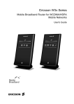
Table 6.1 – Wiring
1.
IN Shield and OUT Shield may be tied together if no GND potential exists between devices.
(Phoenix recommendation)
2.
Optional COM jumper is installed and .001uF “Y” capacitor is installed.
(Phoenix recommendation)
3.
Optional COM jumper is not installed as long as there is not a 7V potential between the
P1 pin 6 and P2 pin 6.
WARNING: If these recommendations are followed, it is crucial that ground potentials of 7V or
higher do not exist between network devices. Equipment damage can result, which is not covered
under warranty.
PAGE 38
26 APR 2000
NOTES
CH. 6