1
Payloads: STS-192c, STS-48c, STS-24c, STS-12c, STS-9c, STS-6c, STS-3c, STS-1, DS3, E3, VT2, E1 Async, VT1.5 Bulk, DS1 Async
Error Injection: B1, B2, B3, BIP-V, Frame, REI-L, REI-P, REI-V, Bit
Error Injection Count: Programmable error burst of 1 to 9999
Error Injection Rate: 2 x 10⁻³ to 1 x 10⁻⁹
Alarm Generation: LOS, LOF, AIS, AIS-L, RDI-L, LOP-P, AIS-P, RDI-P,
PLM-P, TIM-P, UNEQ-P, AIS-V, RDI-V, LOP-V, PLM-V, TIM-V,
UNEQ-V, LOM
Results Measurements
GR-253 Bit Performance: FC (failure counts), BER, LOPS (loss of
pattern sync), %LOPS, ES (errored seconds), %ES, SES (severely
errored seconds), %SES, UAS (unavailable seconds), %UAS, EFS
(error free seconds), %EFS
SONET defects: LOS, LOF, AIS, AIS-L, RDI-L, LOP-P, AIS-P, RDI-P,
PLM-P, TIM-P, UNEQ-P, AIS-V, RDI-V, LOP-V, PLM-V, TIM-V,
UNEQ-V, LOM, B1, B2, B3, BIP-V, Frame, REI-L, REI-P, REI-V,
FC (failure counts), ES (errored seconds), %ES, SES (severely
errored seconds), %SES, UAS (unavailable seconds), %UAS, EFS
(error free seconds), %EFS
SONET Pointer: Justification, Increase, Decrease
Measurements Common to SDH/SONET
Histogram Analysis
Graphical display of SDH/SONET/PDH/T-carriers defects and
anomalies
Resolution
– Last hour with 1 second resolution
– Last 3 days with 1 minute resolution
– Up to 57 days with 15 minutes resolution
Service Disruption Measurement
Resolution: 1 frame (125 ns)
Accuracy: < 50 ns
Propagation Delay Measurement
Round trip signal transmission delay
Measures in ns and UI (Unit Intervals) – from 6 ns to 10 sec
General
Continuous measurement
Elapsed time
Optical power level measurement
Frequency: Received, Maximum, Minimum (frequency deviation in
ppm), ± Wander, Clock slips
SDH/SONET Overhead
Monitor and Transmit Section/Regenerator Section, Line/Multiplex
Section, and Path Overhead bytes
ASCII decode of 16-byte or 64-byte HP/STS or LP/VT Path Trace
bytes (J1/J2)
Programming K1/K2 APS signaling bytes per ITU-T G.783/G.841
K1 and K2 byte capture: 20 transitions (minimum)
Time resolution: 125 ns
Linear and Ring decode of bytes
J0 Section Trace Generation: 1 byte SAPI format or 16 bytes E.164
ASCII sequence + CRC-7
S1 Synchronization Status Messages decode & generation
Path Overhead Monitor
Programmable Orderwire bytes (E1, E2) in binary or HEX format
6
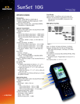
SunSet ® 10G with Electrical Interface Ports
Programming of Path Overhead bytes
J1/J2 Path Trace Generation: 16 bytes E.164 ASCII sequence +
CRC-7 or 64 bytes E.164 ASCII sequence
DCC BER testing through D1 to D3 bytes or D4 to D12 bytes Pattern selection 223-1, 220-1, 215-1, 211-1
C2 signal label byte programming in binary or hexadecimal
G1 bit 5: RDI generation
User programmable path user bytes (F2, F3)
Programmable K3 (24), K4 (27) bytes (bits 1-4) for APS signaling
V5 byte: Signal label generation (bits 5-7), Extended signal label
generation/decode (K4 byte), Enhanced RDI generation/detection
Pointer Monitor: H1, H2, V1, V2 bytes
Pointer Adjustment: Programming of pointer value, NDF, and SS
bits
Pointer Test Control
Modes: Single , burst of 2-8 consecutive justifications
Select increment, decrement, or alternate the pointer value
G.783/GR-253 Pointer Test Sequences
– AU/STS or TU/VT pointer
– Sequences: Single, Burst, Phase, Transient Burst, Periodic,
87-3, 26-1, Opposite (Increase + Decrease), and Custom
– Movement: Increase, Decrease, Increase + Decrease
– Anomalies: Added, Cancel, and None
APS Timing Measurement
Resolution: 1 ms
Accuracy: 1 ms
Sensors: LOS, LOF, MS-AIS/AIS-L, MS-RDI/RDI-L, AU-AIS/AIS-P,
HP-RDI/RDI-P, TU-AIS/AIS-V, LP-RDI/RDI-V
Pass/Fail Indicator
User selectable switch and gate time
Tandem Connections Monitoring
N1, N2 bytes for High and Low Order Paths
Analysis of the data, display of data in the form of alarms,
performance figures, and APId messages as specified in ITU-T
G.707
Generation and detection of the following parameters:
– Loss of Tandem Connection (LTC)
– Incoming Error Count (IEC)
– Tandem Connection Remote Error Indication (TC-REI)
– Tandem Connection Alarm Indication Signal (TC-AIS)
– Tandem Connection Remote Defect Indication (TC-RDI)
– Tandem Connection Outgoing Defect Indication (TC-ODI)
– Tandem Connection Outgoing Error Indication (TC-OEI)
– Tandem Connection UnEquip (TC-UNEQ)
PDH Measurements (139M, 45M, 34M, 2M, 1.5M)
Typical Error Type Reports: Total error count, error rate, ES, %ES,
SES, %SES, UAS, %UAS, EFS, %EFS, AS, %AS
ITU-T G.821 Analysis
ITU-T G.826 Analysis: Based on anomalies, defects, far end indications
M.2100 Analysis (Maintenance or BIS)
Frequency Measurements: Moving bar graph of slip count, max
frequency, min frequency, frequency deviation in ppm, clock
slips, max positive wander, max negative wander