1
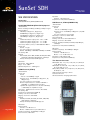
®
SunSet SDH
SDH SPECIFICATIONS
Connectors
FCUPC (SSSDHC16-FC), SCUPC (SSSDHC16-SC)
2.5G/622M/155M/52M (STM-16/4/1/0) Optical
Transmitter
Bit rates 2.5 Gbit/s, 622 Mbit/s, 155 Mbit/s, 52 Mbit/s: ± 4 ppm
Frequency Offset
2.488 Gbit/s ± 50 ppm in 1, 10 ppm steps
622.080 Mbit/s ± 50 ppm in 1, 10 ppm steps
155.520 Mbit/s ± 50 ppm in 1, 10 ppm steps
51.840 Mbit/s ± 50 ppm in 1, 10 ppm steps
Range
1310 nm Short Reach output power: -10 to -3 dBm
1310 nm Long Reach output power: -2 to +3 dBm
1550 nm Long Reach output power: -2 to +3 dBm
Laser Safety: IEC825-1, Class 1, 21 CFR 1040.10 & 1040.11
Clock Source
Internal: ± 4 ppm
Loop: Recovered from received signal
External: 2.048 Mbit/s or 2.048 MHz, 1.544 Mbit/s or 1.544 MHz
Line Coding: NRZ
Payloads
VC4-16c Bulk, VC4-4c Bulk, VC4 Bulk, VC3 Bulk, VC12 Bulk,
VC11 Bulk, 139M, 45M, 34M, 2M Async, 1.5M Async
Framed, Unframed, Structured PDH payloads
Receiver
Wavelength: 1280 -1580 nm
Range: -27 to -9 dBm
Maximum Input Power: -6 dBm typical
155M Electrical (STM-1)
Transmitter
Clock Source
Internal
− Bit rate: 155.520 Mbit/s ± 4 ppm
Frequency offset: 155.520 Mbit/s ± 150 ppm in 1, 10,
100 ppm steps
Loop: Recovered from received signal
External: Synchronization to external 1.544 MHz or
2.048 MHz via 1.5/2M External Clock input
1.5/2M-L2-Rx: Synchronization to external 1.544 Mbit/s
or 2.048 Mbit/s via 1.5/2M Line 2 input
Pulse Shape: 155M electrical conforms to ITU-T G.703
Line Coding: CMI
Port/Connector: 75Ω unbalanced BNC (f)
Framing: Conforms to ITU-T G.707
Mapping: Conforms to ITU-T G.707
Payloads
VC4 Bulk, VC3 Bulk, VC12 Bulk, VC11 Bulk, 139M, 45M,
34M, 2M Async, 1.5M Async
Framed, Unframed, Structured PDH payloads
Receiver
. . . a step ahead
Input Sensitivity
Terminate: 12.7 dB cable loss
Monitor: 20 dB resistive loss plus 6 dB cable loss
Clock Recovery Range: 155.520 Mbit/s ± 150 ppm
Jitter Tolerance to ITU-T G.825
STM-16 version
May 2004
Impedance
Terminate: 75Ω, unbalanced
Port/Connector: 75Ω, unbalanced BNC (f)
52M Electrical, STM-0 (SWSDH-120)
Transmitter
Clock Source
Internal
− Bit rate: 51.840 Mbit/s ± 5 ppm
Frequency offset: 51.840 Mbit/s ± 500 ppm in 1, 10, 100
ppm steps
Loop: Recovered from received signal
Pulse Shape: Conforms to ITU-R F.750-3
Line Coding: B3ZS
Framing: Conforms to ITU-T G.707 Annex A
Mapping: Conforms to ITU-T G.707
Payloads: VC3 Bulk, VC12 Bulk, VC11 Bulk, 45M, 2M Async,
1.5M Async
Port/Connector: 75Ω, unbalanced BNC (f)
Receiver
Clock Recovery Range: 51.840 Mbit/s ± 500 ppm
Input Sensitivity
Terminate: 10.8 dB cable loss
Monitor: +3 to -26 dB resistive loss
Impedances: 75Ω, unbalanced (f)
Port/Connector: 75Ω, unbalanced BNC (f)
Test Pattern Generator
STM-16 (VC4-16c): 2e31, 2e23, 2e20, 2e15, 2e11, All 0s, All
1s, Alt 1010, 1-8, 1-16
STM-16 (VC4-4c and below): 2e23, 2e20, 2e15, 2e11, All 0s,
All 1s, Alt 1010, 1-8, 1-16
STM-4, STM-1, STM-0: 2e23, 2e20, 2e15, 2e11, All 0s, All 1s,
Alt 1010, 1-8, 1-16
10 User Patterns defined up to 16 bits
Test Pattern Inversion
Unselected Channels: Unequipped, Broadcast
®
SunSet SDH
SDH Error Injection/Alarm Generation
Errors
Bit, B1, B2, B3, MS-REI, HP-REI, LP-REI, BIP-2
Programmable error burst 1 to 9999 count, or error rate 2x10⁻³ to 1x10⁻⁹
FAS error injection in periodic mode (burst of M errors every N frames)
Alarms
LOS, LOF, MS-AIS, MS-RDI, AU-AIS, AU-LOP, HP-RDI, HP-UNEQ, TUAIS, TU-LOM, LP-UNEQ, TU-LOP, HP-PLM, LP-PLM, LP-RFI, LP-RDI,
RS-TIM, HP-TIM, LP-TIM
Enhanced RDI [HP/LP-SRDI (Server), HP/LP-CRDI (Connectivity), HP/LPPRDI (Payload)]
Alarm generation in continuous or repetitive mode (burst of M frames
out of N frames)
SDH Measurements (2.5G, 622M, 155M, 52M)
Errors: Bit, B1, B2, B3, BIP-2, MS REI, HP REI, LP REI
Alarms: LOS, LOF, OOF, MS-AIS, MS-RDI, AU-AIS, AU-LOP, HP-RDI, HPUNEQ, TU- AIS, TU-LOM, LP-UNEQ, TU-LOP, HP-TIM, LP-TIM, HP-PLM,
LP-PLM, LP-RFI, LP-RDI, Enhanced RDI [HP/LP-SRDI (Server), HP/LPCRDI (Connectivity), HP/LP-PRDI (Payload)], Extended PLM (LP-EPLM),
Extended LOM (LP-ELOM)
Performance: ITU-T G.821, G.826, G.828, G.829, M.2100/M.2101/M.2110
(Maintenance or BIS)
Optical Power Level Measurement
Range: -8 to -21 dBm
Accuracy: ± 1 dBm
Optical Reception Saturation Indication
Frequency Measurements (test interface and payload): Moving bar graph
of slip count, max frequency, min frequency, frequency deviation in
ppm, clock slips, max positive wander, max negative wander
Automatic Tributary Scan: 80 characters/line report of alarms/errors per
tributary. In-service and out-of-service for 1.5M, 2M, 34M, 45M,
139M, VC3 Bulk, and VC4 Bulk inside STM1/4/16 with full report.
Trace Generation
J0 Section Trace/Generation: 1 byte SAPI format or 16 bytes E.164
ASCII + CRC-7
J1/J2 Path Trace/Generation: 16 bytes E.164 ASCII sequence + CRC-7
or 64 bytes E.164 ASCII sequence
Through Mode for J0, J1, J2 bytes
Stores up to 5 traces per byte with alphanumeric labels
Programmable Expected Trace Data for J0, J1, and J2 bytes
Path Overhead Monitoring and Decoding
Text encoding of all applicable bytes (K1, K2, S1, C2, etc.)
Programmable POH bytes
DCC BER Testing through D1 to D3, D4 to D12 bytes
Orderwire: Talk/listen through E1, E2 bytes
Pointer Monitor
AU (bytes H1 and H2), TU (bytes V1 and V2)
Display number of pointer operations with respect to time
− Instantaneous pointer value display
− Graphical display of pointer movements with histogram format
Pointer Adjustment
Programming of pointer value, NDF and ss bits
Increase and decrease the pointer value
SONET Mode: Setting ss bits to generate/detect SONET signal
SDH-PDH Mux/Demux Testing
Using two sets of physical ports: 2 Tx/2 Rx
The following combinations are applicable:
• 2.5G 0/139M
• 622M 0/139M
• 155M 0/139M
• 2.5G 0/45M
• 622M 0/45M
• 155M E (0)/45M
• 2.5G 0/34M
• 622M 0/34M
• 155M E (0)/34M
• 2.5G 0/2M
• 622M 0/2M
• 155M E (0)/2M
• 2.5G 0/1.5M
• 622M 0/1.5M
• 155M E (0)/1.5M
MuxTest: The test pattern is generated on the low or high speed port
and the BERT is measured on the opposite port
MuxMode: Emulation of a mux for 1.5M/2M payloads only
SDH Features
ITU-T and ETSI mapping
Manual and Graphic configuration
SDH-SDH Mux/Demux Testing (SWSDH-116)
The following combinations are applicable:
• 2.5G 0/622M 0
• 622M 0/155M E (0)
• 2.5G 0/155M E (0) • 622M 0/52M E
• 2.5G 0/52M E
• 155M E (0)/52M E
G.783 Pointer Test Sequences (SWSDH-123)
AU or TU pointer
Sequences: Single, Burst, Phase, Transient Burst, Periodic, 87-3, 26-1,
Opposite (Increase + Decrease), and Custom
Movement: Increase, Decrease, Increase + Decrease
Anomalies: Added, Cancel, and None
Tandem Connections Monitoring (SWSDH-125)
Overhead Monitoring and Decoding
Text encoding of all applicable bytes (K1, K2, S1, C2, etc.)
Full SOH/POH Overhead bytes control in binary or HEX format
Programming K1, K2 APS signalling bytes per ITU-T G.783
Through Modes
Line Through
Payload Through
− All SOH bytes can be modified except for B1, B2, H1, H2 bytes
− Alarms/Error Insertion: LOS, LOF, MS-AIS, MS-RDI, B1, B2, MS-REI
N1 byte for High Order Paths (VC-3/VC-4)
N2 byte for Low Order Paths (VC-11/VC-12)
Analysis of data, display of data in the form of alarms, performance
figures, and APId messages as specified in ITU-T Rec. G.707.
Generation and Detection of the following parameters:
Loss of Tandem Connection (LTC)
Loss of Multiframe (LOM)
Incoming Error Count (IEC)
Tandem Connection Remote Error Indication (TC-REI)
Tandem Connection Alarm Indication Signal (TC-AIS)
Tandem Connection Remote Defect Indication (TC-RDI)
Tandem Connection Outgoing Defect Indication (TC-ODI)
Tandem Connection Outgoing Error Indication (TC-OEI)
Tandem Connection UnEquip (TC-UNEQ)
Tandem Connection Errors Difference (TC-DIFF)
Graphical Display
APS Timing Measurement (SWSDH-126)
Measures time that anomaly is present
Resolution: 1 ms
Anomaly selection: MS-AIS, B2 errors, AU-AIS, TU-AIS, LOS
Selectable switch time to display PASS or FAIL
Selectable gate time to control the minimum interval for the circuit to
be anomaly time
APS timing at 2M interfaces: 2M-AIS, 2M-LOS
APS bytes capture
Capture and decode states of K1/K2 bytes
– Store hundreds of messages
– Ring and Linear Decoding
125 µs resolution
Optional Trigger with wildcards
Timestamp in frames or ms
Duration in absolute or elapsed time
Save or Print results
Load and Decode past results
Service disruption (bulk payloads)
Propagation Delay Measurement
Round trip signal transmission delay
Range: From 1 µs to 5 seconds
Measures in µs and UI (Unit Intervals)
PDH SPECIFICATIONS
139M (SWSDH-112)
Transmitter
Clock Source
Internal
− Bit rate: 139.264 Mbit/s ± 5 ppm
Frequency offset (as test interface and as a payload): 139.264 Mbit/s
± 150 ppm in 1, 10, 100 ppm steps
Loop: Recovered from received signal
Pulse Shape: Conforms to ITU-T G.703
Line Coding: CMI
Port/Connector: 75Ω, unbalanced BNC (f)
Framing: Unframed, Framed, Structured per ITU-T G.751
Error Injection: Code, Bit, Bit+Code, FAS
Programmable error burst 1 to 9999 count or error rate 2 x 10⁻³ to 1 x 10⁻⁹
Alarm Generation: AIS, FAS RAI
Receiver
Clock Recovery Range: 139.264 Mbit/s ± 150 ppm
Input Sensitivity
Terminate: 12 dB cable loss
Monitor: 20 dB resistive loss plus 6 dB cable loss
Jitter Tolerance: Conforms to ITU-T G.823
Impedance
Terminate: 75Ω, unbalanced
Port/Connector: 75Ω, unbalanced BNC (f)
45M (SWSDH-111)
Transmitter
Clock Source
Internal
− Bit rate: 44.736 Mbit/s, ± 5 ppm
Frequency offset (as test interface and as a payload): 44.736 Mbit/s ±
500 ppm in 1, 10, 100 ppm steps
Loop: Recovered from received signal
Line Coding: B3ZS
Pulse Shape: Conforms to ITU-T G.703
Port/Connector: 75Ω, unbalanced BNC (f)
Framing: Unframed, M13, and C-bit
Error Injection: Code, Bit, Code+Bit, Frame, C-bit, P-bit, FEBE
Programmable error burst 1 to 9999 count, or error rate 2 x 10⁻³ to 1 x 10⁻⁹
Alarm Generation: AIS, Yellow, Idle
Receiver
Clock Recovery Range: 44.736 Mbit/s ± 500 ppm
Jitter Tolerance: Conforms to ITU-T G.824
Input Sensitivity
Terminate: Up to -6 dB cable loss
Monitor: +6 dB to -26 dB resistive loss
Impedance
Terminate, Monitor: 75Ω, unbalanced
Port/Connector: 75Ω, unbalanced BNC (f)
34M
Transmitter
Clock Source
Internal
− Bit rate: 34.368 Mbit/s ± 5 ppm
Frequency offset (as test interface and as a payload): 34.368 Mbit/s ±
500 ppm in 1, 10, 100 ppm steps
Loop: Recovered from received signal
Line Coding: HDB3
Pulse Shape: Conforms to ITU-T G.703
Framing: Framed, Unframed, Structured per ITU-T G.751
Error Injection
Code, Bit, Bit+Code, FAS
Programmable error burst 1 to 9999 count, or error rate 2 x 10⁻³ to 1 x 10⁻⁹
Alarm Generation: AIS, FAS RAI
Port/Connector: 75Ω, unbalanced BNC (f)
Receiver
Clock Recovery Range: 34.368 Mbit/s ± 500 ppm
Jitter Tolerance: Conforms to ITU-T G.823
Input Sensitivity
Terminate: -12 dB cable loss
Monitor: -20 dB resistive loss plus -12 dB cable loss
Impedance: 75Ω, unbalanced
Port/Connector: 75Ω, unbalanced BNC (f)
Dual 2M
Transmitters (Lines 1 and 2)
Clock Source
Internal
− Bit rate: 2.048 Mbit/s ± 5 ppm
Frequency offset (as test interface and as a payload): 2.048 Mbit/s ±
5000 ppm in 1, 10, 100, 1000 ppm steps
External Clock Input Port: 2.048 MHz
Recovered from Line 2 input (2.048 Mbit/s)
Loop: Recovered from received signal
Line Coding: AMI, HDB3
Pulse Shape: Conforms to ITU-T G.703 for balanced (120Ω) interfaces
Port/Connector
120Ω: balanced RJ-45 (f) (SSSDHC16-RJ45)
120Ω (SSSDHC-A): balanced, Bantam (SSSDHC16-BTM)
Framing: Unframed, PCM-30, PCM-30C, PCM-31, PCM-31C conforms
to ITU-T G.704
Error Injection
Code, Bit, Bit+Code, CRC-4, E-bit, FAS
Programmable error burst 1 to 9999 count or error rate 2x10⁻³ to 1x10⁻⁹
Alarm Generation: AIS, FAS RAI, MFAS RAI
Fractional E1
Error measurements, channel configuration verification
N or M (noncontiguous) x64 kbit/s, N=1 to 31
Set Tx and Rx channels independently
Through Mode: Test pattern on selected channels; all others through
Receivers (Lines 1 and 2)
Clock Recovery Range: 1.544 Mbit/s ± 500 ppm
Jitter Tolerance: Conforms to ITU-T G.824
Input Sensitivity
Terminate, Bridge: +6 to -36 dB cable loss
Monitor: -15 to -25 dB, resistive loss
Impedance
Terminate, Monitor Mode: 100Ω, balanced
Bridge: > 750Ω
Port/Connector
100Ω, balanced RJ-45 (f) (SSSDHC16-RJ45)
100Ω (SSSDHC-A): balanced, Bantam (SSSDHC16-BTM)
Test Pattern Generator
2e23, 2e20, 2e15, 2e11, 2e9, 2e7, 2e6, All 0s, All 1s, Alt 1010, 20ITU,
QRS, 1-8, 1-16, 3-24
10 User Patterns defined up to 32 bits
Test Pattern Inversion
Receivers (Lines 1 and 2)
PDH/T-Carrier Measurements (139M, 45M, 34M, 2M, 1.5M)
Clock Recovery Range: 2.048 Mbit/s ± 5000 ppm
Jitter Tolerance: Conforms to ITU-T G.823
Input Sensitivity
Terminate, Bridge: +6 to -43 dB with ALBO
Monitor: -20 dB resistive loss plus -6 dB cable loss
Impedance
Terminate, Monitor: 120Ω balanced
Bridge: > 750Ω
Port/Connector
120Ω: balanced RJ-45 (f) (SSSDHC16-RJ45)
120Ω (SSSDHC-A): balanced, Bantam (SSSDHC16-BTM)
Error Type
Code, bit, FASE (2M, 8M, 34M, 139M)
CRC-4, E-bit (2M)
Code (BPV), F-bit, P-bit, C-bit, FEBE, CRC-6 (1.5M, 45M)
Typical Error Type Reports: Total error count, error rate, ES, %ES, SES,
%SES, UAS, %UAS, EFS, %EFS, AS, %AS
ITU-T G.821 Analysis
ITU-T G.826 Analysis: Based on anomalies, defects, far end indications
M.2100 Analysis (Maintenance or BIS)
Alarm Statistics
Loss of signal seconds, Loss of Frame seconds, AIS seconds
FAS RAI seconds (2M, 34M, 139M)
MFAS RAI seconds (2M only)
Yellow alarm seconds (1.5M, 45M)
Low density seconds, excess 0s seconds (1.5M)
Frequency Measurements: Moving bar graph of slip count, max
frequency, min frequency, frequency deviation in ppm, clock slips,
max positive wander, max negative wander
Signal Level Measurement (1.5/2M/34M/45M)
Dual 1.5M (SWSDH-110)
Transmitters (Lines 1 and 2)
Clock Source
Internal
− Bit rate: 1.544 Mbit/s ± 5 ppm
Frequency offset (as test interface and as a payload): 1.544 Mbit/s
± 500 ppm in 1, 10, 100 ppm steps
External Clock Input Port: 1.544 MHz
Recovered from Line 2 input (1.544 Mbit/s)
Loop: Recovered from received signal
Line Coding: AMI, B8ZS
Pulse Shape: Conforms to ITU-T G.703
Port/Connector
100Ω, balanced RJ-45 (f) (SSSDHC16-RJ45)
100Ω (SSSDHC-A): balanced, Bantam (SSSDHC16-BTM)
Framing: Unframed, SF-D4, ESF. Conforms to ANSI T1.102, 107, 107A,
403, and 404. Also Telcordia TR-TSY-000009 and TR-TSY-000191.
Error Injection
BPV, Logic, Logic+BPV, CRC-6, Frame
Programmable error burst 1 to 9999 count or error rate 2x10⁻³ to 1x10⁻⁹
Alarm Generation: AIS, Yellow, Idle
Fractional T1
Error measurements, channel configuration verification
Nx64 kbit/s, Nx56 kbit/s, N=1 to 24
Set Tx and Rx channels independently
Through Mode: Test pattern on selected channels; all others through
PDH Mux/Demux Testing (SWSDH-113)
Using two sets of physical ports: 2 Tx/2 Rx
The following combinations are applicable:
• 139M/34M
• 45M/2M
• 34M/2M
• 139M/2M
• 45M/1.5M
MuxTest: The test pattern is generated on the low or high speed port
and the BERT is measured on the opposite port
Propagation Delay Measurement
Round trip signal transmission delay
Measures in µs and UI (Unit Intervals)
Voice Frequency Testing (SWSDH-114)
Monitor speaker with volume control
Built-in microphone/speaker
Companding Law: A-law (2M); µ law (1.5M)
Programmable idle channel A, B (C, D) bits (1.5M)
ABCD bits transmit and monitor in selected channel (2M)
VF Level and Frequency Measurement
Level: +3 to -60 dBm, resolution 0.1 dBm
Frequency: 50 to 3950 Hz, resolution 1 Hz
VF Tone Generation
Variable tone: 50 to 3950 Hz @ 1 Hz step. +3 to -60 dBm @ 1 dBm
Peak Code and Coder offset measurements
Noise Measurements
Receiver Filters
2M: 3.1 kHz, Psophometric, 1010 Hz notch
1.5M: 3 kHz flat, C-message, C-notch
Printer: Report printing via serial port, RS-232 DIN-9
Network: 10Base-T DIN-9
Battery: Built-in NiMH rechargeable battery pack
Power: AC operation w/100 to 240 VAC, 50/60 Hz universal charger
Environmental
Operating temperature: 0 to 45°C
Storage temperature: -20 to 70°C
Humidity: 5% to 90% noncondensing
Size: 11 x 7 x 27 cm
Weight: 1.5 kg
COMMON TO SDH/PDH/T-CARRIERS
ORDERING INFORMATION
Auto Configuration
SSSDHC-STM16
Single button configuration
Automatically scans all test interfaces for signal
Configures test set based on received signal. Sets rate, mapping,
payload, and/or test pattern.
Optics Options1
Measurement Criteria
Test results/events storage and events log capability
Stores up to 20 test results or 800 errors or alarms events w/user definable labels; lock/unlock records, available to screen view or print
Stores up to 10 user configurations (profiles) with alphanumeric labels
Print on event can be enabled or disabled
Print at timed interval (settable from 2 min up to 999 hr 59 min)
Measurement duration continuous or timed (settable up to 999 hr, 59 min)
Elapsed time, remaining time
Programmable start date and time
Audible alarm: On/off switchable
SSSDHC16-NONE
SS25G-13SR
SS25G-13LR
SS25G-15LR
SS25G-13SR/15LR
SS25G-13LR/15LR
SunSet SDHC STM-16, 2M, 34M, and 155M test
interfaces. RS232C and 10Base-T ports.
Electrical only unit. (BNC) No optical Connectors
Optical Interface, STM-0/1/4/16 1310 nm Short Reach
Optical Interface, STM-0/1/4/16 1310 nm Long Reach
Optical Interface, STM-0/1/4/16 1550 nm Long Reach
Optical Interface, STM-0/1/4/16 1310 nm Short Reach
1550 nm Long Reach
Optical Interface, STM-0/1/4/16 1310/1550 nm Long Reach
Optical Interface Connector Options1
SSSDHC16-FC
SSSDHC16-SC
FCUPC Optical Connectors
SCUPC Optical Connectors
Electrical Interface Connector Options1
SSSDHC16-RJ45
SSSDHC16-BTM
1.5/2M RJ45 Connectors
1.5M/2M Bantam Connectors
Histogram Analysis (SWSDH16-101)
Errors/Alarms/Pointer graphic display in real-time
Stores current results, last 60 days with 15 min resolution, last 72
hours with 1 min resolution, last 60 min with 1 second resolution
CSV format storage
Standard & Configurable Accessories Options
Status and Alarm Indicators
SS138E
Power and low battery LED indicators
Pattern Sync and Bit Error
139M and STM-N (signal), Alarm, Frame, Errors, Pointer, ATM cell
8M, 34M and 45M (signal), Alarm, Frame, and Errors
1.5/2M-L2, Alarm, Errors
1.5/2M-L1, Alarm, Errors
SSSDHC-101
SA904
Power Cord 1
SA155-EU
SA155-NA
Protocols (optional)
GSM Voice and TRAU, GSM A-bis, V5.x Monitoring, Frame Relay, SS7
(TUP, ISUP, BSSAP [DTAP+MAP, BTNUP, SSUTR2]), ISDN (ETSI,
DPNSS, DASS2, AUSSI), VF Call Analysis & Emulation over 1.5M and
2M, Frame Relay, ATM - Refer to respective protocol Specifications
for further information.
GENERAL
Upgrades: SW options upgradeable via software in-field cartridge
replacement
Display: Backlit 320 x 240 pixels STN indoor/outdoor Color screen
with CFL Backlight
SunSet SDH User's Manual
Training CD
[Available at no charge with purchase of SunSet SDH,
when specified at time of order]
SunSet AC Adapter, 100-240 VAC, 50/60 Hz, 3-prong
input, Output 15 VDC @ 3.3A
[Only for use with SunSets equipped with NiMH
battery pack]
SA155-UK
2-Prong power cord plus ground for use in Europe
(Except UK)
3-prong power cord for use in Latin America, North
America, and Asia
3-prong power cord for use in United Kingdom
Warranty 1
SSSDHC-W1
SSSDHC-W2
SSSDHC-W3
SSSDHC-W4
1
Standard 1 year warranty
Extends standard warranty to 2 years
[Excludes Battery and Accessories, which are
warranted for one-year]
Extends standard warranty to 3 years (Standard for
North America) [Excludes Battery and Accessories,
which are warranted for one-year]
Extends standard warranty to 4 years
[Excludes Battery and Accessories, which are
warranted for one-year]
Mutually exclusive options. Must select only one.
SWSDH16-WIN-C
SWSDH16-101
SWSDH-110
SWSDH-111
SWSDH-112
SWSDH-113
SWSDH-114
SWSDH-115
SWSDH-116
SWSDH-120
SWSDH-123
SWSDH-125
SWSDH-126
SWSDH-129
SWSDH-130
SWSDH-131
SWSDH-132
SWSDH-133
SWSDH-134
SWSDH-140
SWSDH-141
SWSDH-149
SWSDH-150
SWSDH-160
SWSDH-161
SWSDH-170
SWSDH-171
SWSDH-172
SWSDH-173
SWSDH-174
SWSDH-175
SWSDH-176
SWSDH-177
SWSDH-178
SWSDH-181
SWSDH-182
SWSDH-183
SWSDH-184
SWSDH-ATM
SSSDHC-ATM
Optical Accessories
SA501
SA502
SA503
SA508
SA509
SA511
SA512
SA521
SA523
SA524
SA531
SA541
SA545
SA551
SA555
Optical Patch Cord, SMF, FC-PC to SC-PC, 6'
Optical Patch Cord, SMF, FC-PC to SC-PC, 6'
Optical Patch Cord, SMF, FC-PC to ST-PC, 6'
Optical Patch Cord, LCUPC to SCUPC, 6'
Optical Patch Cord, LCUPC to FCUPC, 6'
Optical Patch Cord, SC to SC, 6'
Optical Patch Cord, SC to ST, 6'
Optical Attenuator, FC-PC, -10 dB
Optical Connector Adapter, FC/PC to SC/PC
Optical Connector Adapter SC/PC to FC/PC
[Changes a SC (f) appearance to a FC (f)
appearance]
Optical Attenuator, SC-PC, -10 dB
Optical Splitter, FC-PC, 90/10
Optical Splitter, FC-PC, 50/50
Optical Splitter, SC-PC, 90/10
Optical Splitter, SC-PC, 50/50
Other Accessories
Refer to Price List
IS
LE
E TE C O M
N C.
IS
O
Note: Specifications subject to change without notice. All product
and company names are trademarks of their respective corporations.
© 2004 Sunrise Telecom Incorporated. All rights reserved. Printed in USA.
REV:040426
,I
Windows Remote Control
Histogram Analysis
1.5 Mbps Testing
45 Mbps Testing
139 Mbps Testing
PDH Mux-demux Testing
Voice Frequency Testing
VF Call Analysis & Call Emulation over 1.5M
[Includes User's Manual SSSDHC-101-8]
SDH-SDH Mux/Demux Testing
52 Mbps Testing
G.783 Pointer Test sequences
Tandem Connections Monitoring
APS Switching Timing
1.5 Mbps ATM Testing
[Includes User's Manual SSSDHC-101-3]
2 Mbps ATM Testing
[Includes User's Manual SSSDHC-101-3.]
45 Mbps ATM Testing
[Includes User's Manual SSSDHC-101-3]
34 and 155 Mbps ATM Testing
[Includes User's Manual SSSDHC-101-3]
622 Mbps ATM Testing
[Includes User's Manual SSSDHC-101-3]
2.5 Gbps ATM Testing
[Includes User's Manual SSSDHC-101-3]
GSM Voice and TRAU Access Option
[Includes User's Manual SSSDHC-101-1]
GSM A-bis
[Includes SSSDHC-101-1]
V.5x Monitoring
[Includes User's Manual SSSDHC-101-2]
3 Timeslot V5.2 Monitoring
[Requires SWSDH-149]
Frame Relay
[Includes User's Manual SSSDHC-101-7]
Frame Relay NNI
[Requires SWSDH-160]
SS7 over 2M Analysis
[Includes User's Manual SSSDHC-101-5]
TUP Analysis ITU Standard
[Requires SWSDH-170]
ISUP Analysis ITU Standard
[Requires SWSDH-170]
ISUP Analysis Chinese Standard
[Requires SWSDH-170]
ISUP Analysis Italian Standard
[Requires SWSDH-170]
Mobile Application Part BSSAP (DTAP+MAP)
[Requires SWSDH-170]
BTNUP Analysis
[Requires SWSDH-170]
SS7 over 1.5M Analysis
[Includes User's Manual SSSDHC-101-5]
ISUP Analysis ANSI Standard
[Requires SWSDH-170 or SWSDH-177]
SWSDH-180
SSUTR2 French TUP R2
[Requires SWSDH-170]
ISDN Monitoring & Call Emulation
[Includes User's Manual SSSDHC-101-6]
ETSI (EuroISDN) Protocol
[Requires SWSDH-180]
DPNSS Protocol
[Requires SWSDH-180]
DASS2 Protocol
[Requires SWSDH-180]
AUSSI Protocol
[Requires SWSDH-180]
ATM Software Package
[Includes SWSDH-130 and SWSDH-132]
VC12 ATM Testing
[Hardware option to allow for 2M and
VC12B payload for ATM STM 1/4/16 modes
and VBR capability]
0
Software Packages
SWSDH-179
90
38
Certificate of Calibration and Compliance
with Measurement Data
[Must be specified at time of order. Only a
printout of the test record is provided.]
R
SSSDHC-CCM
SUN
Calibration Data Document
302 Enzo Drive
San Jose, CA 95138 USA
ph 1 408 363 8000
fax 1 408 363 8313
[email protected]
01 - A6
www.sunrisetelecom.com